sensor MITSUBISHI GRANDIS 2010 Owner's Manual (in English)
[x] Cancel search | Manufacturer: MITSUBISHI, Model Year: 2010, Model line: GRANDIS, Model: MITSUBISHI GRANDIS 2010Pages: 273, PDF Size: 21.01 MB
Page 13 of 273
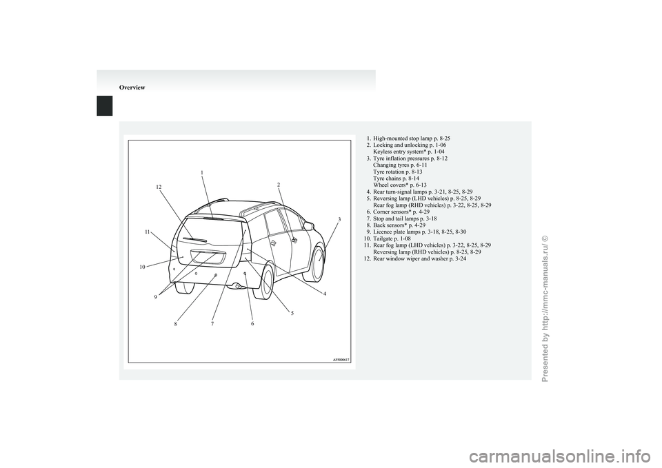
1. High-mounted stop lamp p. 8-25
2.
Locking and unlocking p. 1-06Keyless entry system* p. 1-04
3. Tyre inflation pressures p. 8-12 Changing tyres p. 6-11
Tyre rotation p. 8-13
Tyre chains p. 8-14
Wheel covers* p. 6-13
4. Rear turn-signal lamps p. 3-21, 8-25, 8-29
5. Reversing lamp (LHD vehicles) p. 8-25, 8-29 Rear fog lamp (RHD vehicles) p. 3-22, 8-25, 8-29
6. Corner sensors* p. 4-29
7. Stop and tail lamps p. 3-18
8. Back sensors* p. 4-29
9. Licence plate lamps p. 3-18, 8-25, 8-30
10. Tailgate p. 1-08
11. Rear fog lamp (LHD vehicles) p. 3-22, 8-25, 8-29 Reversing lamp (RHD vehicles) p. 8-25, 8-29
12. Rear window wiper and washer p. 3-24 Overview1
2
3
4
5
6
7
8
9
10 1
1 12
Presented by http://mmc-manuals.ru/ \251
Page 54 of 273
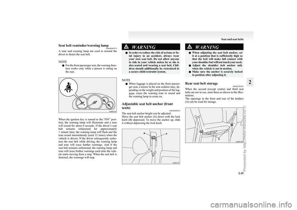
Seat belt reminder/warning lamp
E00409800774
A
tone and warning lamp are used to remind the
driver to fasten the seat belt.
NOTE
l For the front passenger seat, the warning func-
tion works only while a person is sitting on
the seat. When the ignition key is turned to the “ON” posi-
tion,
the warning lamp will illuminate and a tone
will sound for about 6 seconds. If the driver’s seat
belt remains unfastened for approximately
1 minute later, the warning lamp will flash and the
tone sound intermittently (each 12 times) when the
vehicle is driven. If the driver subsequently unfas-
tens the seat belt while driving, the warning lamp
and tone will issue further warnings. And if the
seat belt remains unfastened, the warning lamp and
tone will issue further warnings each time the vehi-
cle starts moving from a stop. When the seat belt is
fastened, the warnings will stop. WARNING
l In
order to reduce the risk of serious or fa-
tal injury in an accident, always wear
your own seat belt. Do not allow anyone
to ride in your vehicle unless he or she is
also seated and wearing a seat belt. Chil-
dren should additionally be restrained in
a secure child restraint system.
NOTE l When
luggage is placed on the front passen-
ger seat, a sensor in the seat cushion may, de-
pending on the weight and position of the lug-
gage, cause the warning tone to sound and
the warning lamp to come on.
Adjustable seat belt anchor (front
seats) E00405000433
The seat belt anchor height can be adjusted.
Move
the seat belt anchor (A) down with the lock
knob (B) depressed. To move the anchor up, slide
it without depressing the lock knob. WARNING
l When
adjusting the seat belt anchor, set
it at a position that is sufficiently high so
that the belt will make full contact with
your shoulder but will not touch your neck.
l Adjust the shoulder belt anchor only
when the vehicle is not in motion.
l Make sure the anchor is securely locked
in position after adjusting it.
Rear seat belt storage E00405300393
When the second (except centre) and third seat
belts
are not in use, store them as shown in the illus-
trations.
The openings in the front and rear of the holders
(A) can be used for storage. Seat and seat belts
2-19 2
Presented by http://mmc-manuals.ru/ \251
Page 55 of 273
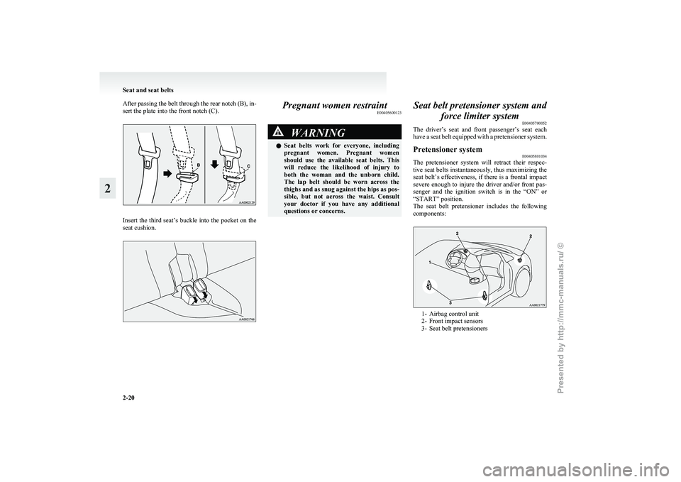
After passing the belt through the rear notch (B), in-
sert the plate into the front notch (C).
Insert the third seat’s buckle into the pocket on the
seat cushion. Pregnant women restraint
E00405600123 WARNING
l Seat belts work for everyone, including
pregnant women. Pregnant women
should use the available seat belts. This
will reduce the likelihood of injury to
both the woman and the unborn child.
The lap belt should be worn across the
thighs and as snug against the hips as pos-
sible, but not across the waist. Consult
your doctor if you have any additional
questions or concerns. Seat belt pretensioner system and
force limiter system E00405700052
The
driver’s seat and front passenger’s seat each
have a seat belt equipped with a pretensioner system.
Pretensioner system E00405801034
The pretensioner system will retract their respec-
tive
seat belts instantaneously, thus maximizing the
seat belt’s effectiveness, if there is a frontal impact
severe enough to injure the driver and/or front pas-
senger and the ignition switch is in the “ON” or
“START” position.
The seat belt pretensioner includes the following
components: 1- Airbag control unit
2-
Front impact sensors
3- Seat belt pretensioners Seat and seat belts
2-20
2
Presented by http://mmc-manuals.ru/ \251
Page 64 of 273
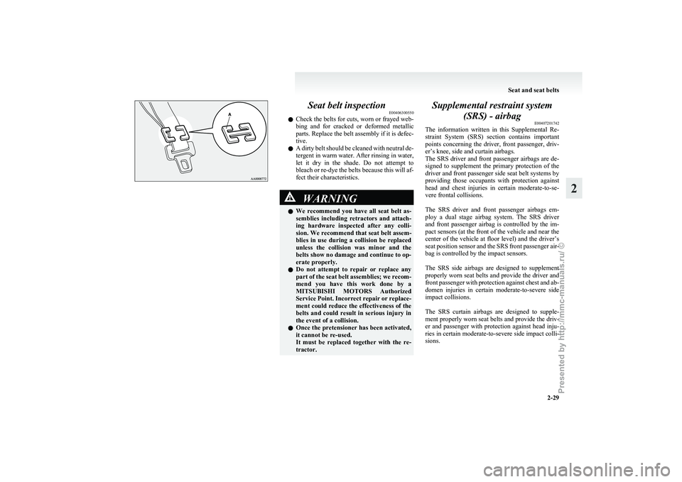
Seat belt inspection
E00406300550
l Check
the belts for cuts, worn or frayed web-
bing and for cracked or deformed metallic
parts. Replace the belt assembly if it is defec-
tive.
l A dirty belt should be cleaned with neutral de-
tergent in warm water. After rinsing in water,
let it dry in the shade. Do not attempt to
bleach or re-dye the belts because this will af-
fect their characteristics. WARNING
l We
recommend you have all seat belt as-
semblies including retractors and attach-
ing hardware inspected after any colli-
sion. We recommend that seat belt assem-
blies in use during a collision be replaced
unless the collision was minor and the
belts show no damage and continue to op-
erate properly.
l Do not attempt to repair or replace any
part of the seat belt assemblies; we recom-
mend you have this work done by a
MITSUBISHI MOTORS Authorized
Service Point. Incorrect repair or replace-
ment could reduce the effectiveness of the
belts and could result in serious injury in
the event of a collision.
l Once the pretensioner has been activated,
it cannot be re-used.
It must be replaced together with the re-
tractor. Supplemental restraint system
(SRS) - airbag E00407201742
The
information written in this Supplemental Re-
straint System (SRS) section contains important
points concerning the driver, front passenger, driv-
er’s knee, side and curtain airbags.
The SRS driver and front passenger airbags are de-
signed to supplement the primary protection of the
driver and front passenger side seat belt systems by
providing those occupants with protection against
head and chest injuries in certain moderate-to-se-
vere frontal collisions.
The SRS driver and front passenger airbags em-
ploy a dual stage airbag system. The SRS driver
and front passenger airbag is controlled by the im-
pact sensors (at the front of the vehicle and near the
center of the vehicle at floor level) and the driver’s
seat position sensor and the SRS front passenger air-
bag is controlled by the impact sensors.
The SRS side airbags are designed to supplement
properly worn seat belts and provide the driver and
front passenger with protection against chest and ab-
domen injuries in certain moderate-to-severe side
impact collisions.
The SRS curtain airbags are designed to supple-
ment properly worn seat belts and provide the driv-
er and passenger with protection against head inju-
ries in certain moderate-to-severe side impact colli-
sions.
Seat and seat belts
2-29 2
Presented by http://mmc-manuals.ru/ \251
Page 67 of 273
WARNING
l Extreme Hazard!
Do
not use a rearward facing child re-
straint on a seat protected by an airbag in
front of it! How the Supplemental Restraint Sys-
tem works
E00407300935
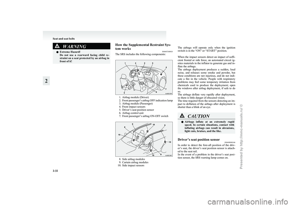
The SRS includes the following components: 1. Airbag module (Driver)
2. Front
passenger’s airbag OFF indication lamp
3. Airbag module (Passenger)
4. Front impact sensors
5. Driver’s seat position sensor
6. Airbag control unit
7. Front passenger’s airbag ON-OFF switch 8. Side airbag modules
9.
Curtain airbag modules
10. Side impact sensors
The
airbags will operate only when the ignition
switch is in the “ON” or “START” position.
When the impact sensors detect an impact of suffi-
cient frontal or side force, an automated circuit ig-
nites materials in the inflator to generate gas and in-
flate the airbags.
The airbags deployment produces a sudden, loud
noise, and releases some smoke and powder, but
these conditions are not injurious, and do not indi-
cate a fire in the vehicle. People with respiratory
problems may feel some temporary irritation from
chemicals used to produce the deployment; open
the windows after airbag deployment, if safe to do
so.
The airbags deflate very rapidly after deployment,
so there is little danger of obscured vision.
The time required from the sensors detecting an im-
pact to deflation of the airbags after deployment is
shorter than a blink of an eye. CAUTION
l
Airbags
inflate at an extremely rapid
speed. In certain situations, contact with
inflating airbags can result in abrasions,
light cuts, bruises, and the like.
Driver’s seat position sensor E00409900166
In order to detect the fore-aft position of the driv-
er’s
seat, the driver’s seat position sensor is attach-
ed to the seat rail.
In the event of a problem in the driver’s seat posi-
tion sensor, the SRS warning lamp comes on. Seat and seat belts
2-32
2
Presented by http://mmc-manuals.ru/ \251
Page 68 of 273
WARNING
l If the SRS warning lamp comes on, we rec-
ommend you to have the vehicle inspec-
ted by a MITSUBISHI MOTORS Author-
ized Service Point as soon as possible.
l Please observe the following instructions
to ensure that the driver’s seat position
sensor can sense the seat position correct-
ly. Otherwise, the dual stage airbags may
not operate correctly.
• Adjust the seat to the correct position,and sit correctly with your back
against the seatback.
Refer to “Front seat” on page 2-05.
• Do not have the seatback reclined more than necessary when driving.
• Do not place metallic objects or lug- gage under the seat.
l If the vehicle suffers a severe impact, we
recommend you to have the sensor inspec-
ted by a MITSUBISHI MOTORS Author-
ized Service Point as soon as possible.
Front passenger’s airbag ON-OFF
switch E00410100214
The front passenger’s airbag ON-OFF
switch can
be used to disable the front passenger’s airbag. If
you have a rearward facing child restraint system
that cannot be fitted to any seat other than the front
passenger seat, be sure to turn OFF the front passen-
ger’s airbag ON-OFF switch before using it. (Refer
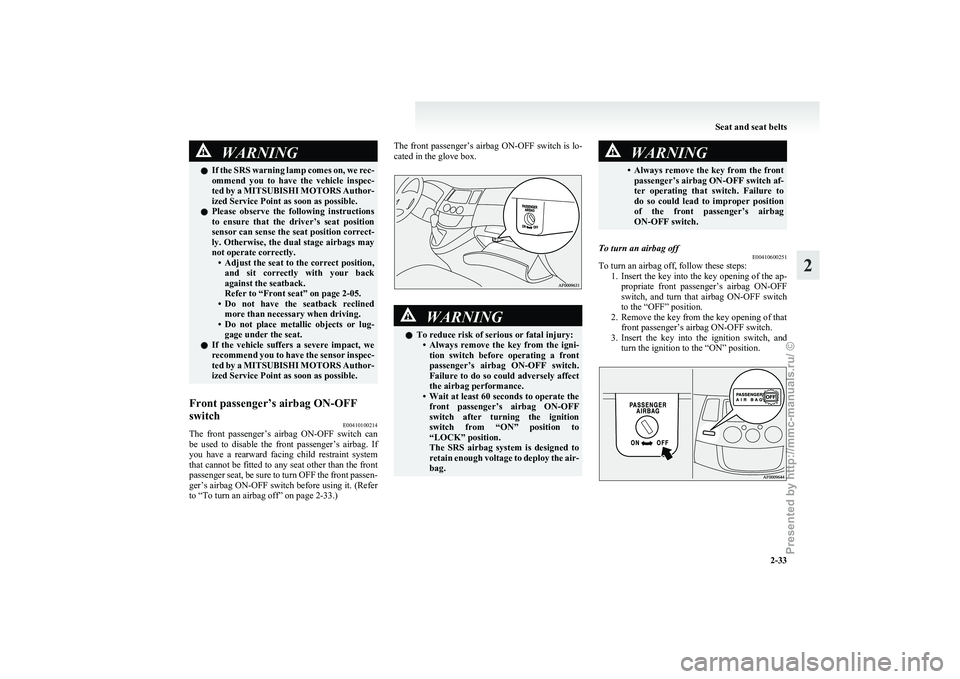
to “To turn an airbag off” on page 2-33.) The front passenger’s airbag ON-OFF
switch is lo-
cated in the glove box. WARNING
l To reduce risk of serious or fatal injury:
• Always
remove the key from the igni-
tion switch before operating a front
passenger’s airbag ON-OFF switch.
Failure to do so could adversely affect
the airbag performance.
• Wait at least 60 seconds to operate the front passenger’s airbag ON-OFF
switch after turning the ignition
switch from “ON” position to
“LOCK” position.
The SRS airbag system is designed to
retain enough voltage to deploy the air-
bag. WARNING
• Always
remove the key from the front passenger’s airbag ON-OFF switch af-
ter operating that switch. Failure to
do so could lead to improper position
of the front passenger’s airbag
ON-OFF switch.
To turn an airbag off E00410600251
To turn an airbag off, follow these steps:
1. Insert
the key into the key opening of the ap-
propriate front passenger’s airbag ON-OFF
switch, and turn that airbag ON-OFF switch
to the “OFF” position.
2. Remove the key from the key opening of that front passenger’s airbag ON-OFF switch.
3. Insert the key into the ignition switch, and turn the ignition to the “ON” position. Seat and seat belts
2-33 2
Presented by http://mmc-manuals.ru/ \251
Page 77 of 273
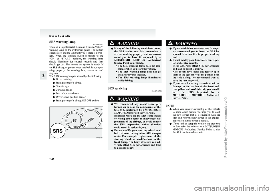
SRS warning lamp
E00407800653
There
is a Supplemental Restraint System (“SRS”)
warning lamp on the instrument panel. The system
checks itself and the lamp tells you if there is a prob-
lem. When the ignition switch is turned to the
“ON” or “START” position, the warning lamp
should illuminate for several seconds and then
should go out. This means the system is ready. If
an SRS airbag or pretensioner seat belt is not oper-
ating properly, the warning lamp comes on and
stays on.
The SRS warning lamp is shared by the following:
l Driver’s airbag
l Front passenger’s airbag
l Side airbags
l Curtain airbags
l Seat belt pretensioners
l Driver’s seat position sensor
l Front passenger’s airbag ON-OFF switch WARNING
l If
any of the following conditions occur,
the SRS and/or seat belt pretensioners
are not working properly, and we recom-
mend you to have it inspected by a
MITSUBISHI MOTORS Authorized
Service Point immediately. • The SRS warning lamp does not illu-minate when you start the vehicle.
• The SRS warning lamp does not go out after several seconds.
• The SRS warning lamp illuminates while driving.
SRS servicing E00407900726 WARNING
l We
recommend any maintenance per-
formed on or near the components of the
SRS to be performed by a MITSUBISHI
MOTORS Authorized Service Point.
Improper work on the SRS components
or wiring could result in inadvertent de-
ployment of the airbags, or could render
the SRS inoperative; either situation
could result in serious injury.
l Do not modify your steering wheel, seat
belt retractor or any other SRS compo-
nents. For example, replacement of the
steering wheel, or modifications to the
front bumper or body structure can ad-
versely affect SRS performance and lead
to possible injury. WARNING
l If
your vehicle has sustained any damage,
we recommend you to have the SRS in-
spected to ensure it is in proper working
order.
l Do not modify your front seats, centre pil-
lar and centre console.
It can adversely affect SRS performance
and lead to possible injury.
Also, if you have found any tear or open
seam in the seat fabric at the portion near
the side airbag, we recommend you to
have the seat inspected.
l If you have found any scratch, crack or
damage to the portion of the front and
rear pillars and roof side rail, you should
have the SRS inspected by a
MITSUBISHI MOTORS Authorized
Service Point.
NOTE l When
you transfer ownership of the vehicle
to some other person, we urge you to alert
the new owner that it is equipped with the
SRS and refer the new owner to the applica-
ble section in this owner’s manual.
l If you junk or scrap the vehicle, we urge you
to first take the vehicle to a MITSUBISHI
MOTORS Authorized Service Point so that
the SRS can be rendered safe. Seat and seat belts
2-42
2
Presented by http://mmc-manuals.ru/ \251
Page 104 of 273
Economical driving.......................................................................4-02
Driving, alcohol and drugs
........................................................... 4-02
Safe driving techniques ................................................................ 4-03
Running-in recommendations
.......................................................4-03
Parking brake................................................................................ 4-04
Parking.......................................................................................... 4-05
Steering wheel height adjustment .................................................4-06
Inside rear-view mirror ................................................................. 4-06
Outside rear-view mirrors ............................................................. 4-07
Ignition switch .............................................................................. 4-08
Steering wheel lock ...................................................................... 4-10
Starting..........................................................................................4-10
Diesel particulate filter (DPF)* .................................................... 4-12
Manual transmission* ................................................................... 4-13
Automatic transmission INVECS-II Sports Mode 4A/T (Intelligent & Innovative Vehicle Electronic Control
System II)*............................................................................... 4-15
Braking......................................................................................... 4-20
Anti-lock brake system (ABS) ..................................................... 4-21
Power steering system.................................................................. 4-23
Active stability control (ASC)* .................................................... 4-23
Auto-speed (cruise) control* ........................................................ 4-25
Corner sensor system*.................................................................. 4-29
Cargo loads................................................................................... 4-32
Trailer towing ............................................................................... 4-34Starting and driving
4
Presented by http://mmc-manuals.ru/ \251
Page 125 of 273
CAUTION
l
If the warning lamp stays on or does not
illuminate when you start the vehicle, it in-
dicates that the ABS is not functioning
and that only the standard brake system
is in operation. (In this condition the stand-
ard hydraulic brake system will still func-
tion.)
We recommend you to consult a
MITSUBISHI MOTORS Authorized
Service Point.
If the warning lamp illuminates while
driving E00607300940
If only the ABS warning lamp illuminates l Avoid
hard braking and high-speed driving.
Stop the vehicle in a safe place.
Restart the engine and check to see whether
the lamp goes out after a few minutes driv-
ing; if it then remains off during driving,
there is no problem.
However, if the lamp does not go out, or if it
lights up again when the vehicle is driven,
we recommend you to consult a
MITSUBISHI MOTORS Authorized Service
Point. l
The
ABS warning lamp can illuminate if the
battery voltage is insufficient when the en-
gine is started. In this case, it does not indi-
cate an ABS fault.
Charge the battery by allowing the engine to
idle for a while.
If the battery has been charged but the ABS
warning lamp continues to illuminate or illu-
minates intermittently, we recommend you
to consult a MITSUBISHI MOTORS Author-
ized Service Point.
If the ABS warning lamp and brake warning
lamp illuminate at the same time l The ABS and brake force distribution func-
tion may not work, so hard braking could
make the vehicle unstable.
Avoid hard braking and high-speed driving.
Stop the vehicle in a safe place and we rec-
ommend you to consult a MITSUBISHI
MOTORS Authorized Service Point.
NOTE l Immediately after the vehicle starts moving
after engine start up, a whining sound of a mo-
tor will be heard from the engine compart-
ment. If the brake pedal is depressed at that
moment, you can feel the brake pedal pulsat-
ing.
This pulsation is due to the self-diagnosis op-
eration of the ABS and does not indicate a
malfunction.
l After driving on snowy roads, remove any
snow and ice which may have become ad-
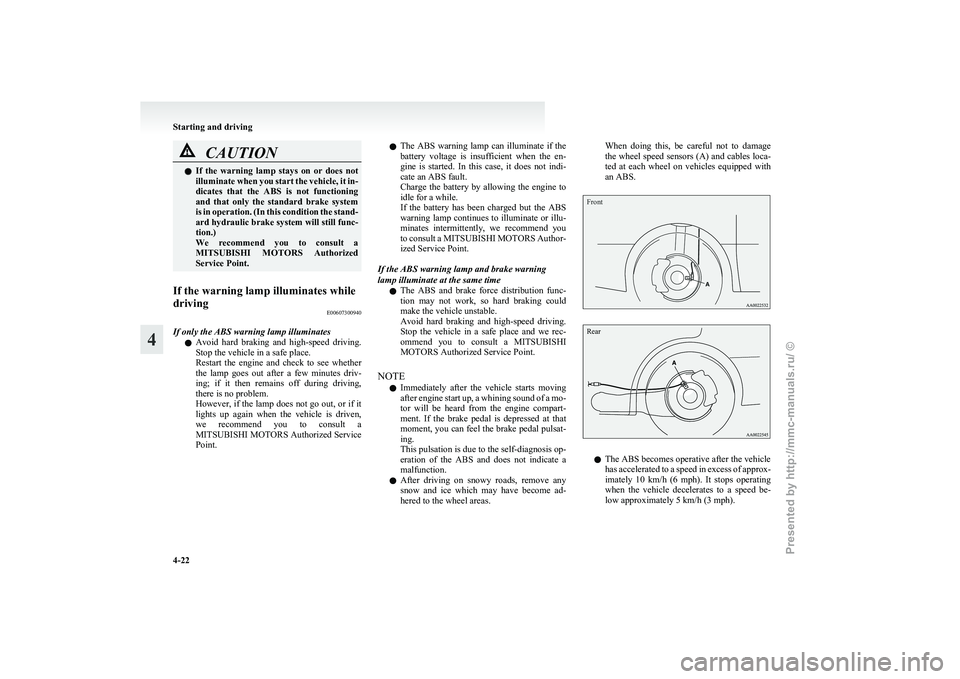
hered to the wheel areas. When doing this, be careful not to damage
the
wheel speed sensors (A) and cables loca-
ted at each wheel on vehicles equipped with
an ABS.
Front
Rear l
The ABS becomes operative after the vehicle
has
accelerated to a speed in excess of approx-
imately 10 km/h (6 mph). It stops operating
when the vehicle decelerates to a speed be-
low approximately 5 km/h (3 mph). Starting and driving
4-22
4
Presented by http://mmc-manuals.ru/ \251
Page 132 of 273
Corner sensor system*
E00615500039
This
system operates when you are backing the ve-
hicle. It uses corner and back sensors to detect an
obstacle and sounds a buzzer to inform you of the
approximate distance to the obstacle. CAUTION
l
The
corner sensor system assists you in de-
termining the approximate distance be-
tween the vehicle and an obstacle located
behind the vehicle. It has limitations in
terms of detectable areas and objects,
and may not properly detect some ob-
jects. Therefore, do not place excessive
confidence in the corner sensor system,
and operate the vehicle as carefully as
you would a vehicle without this system.
l Make sure to check the surroundings
with your own eyes to ensure safety. Do
not operate the vehicle by relying on the
corner sensor system alone.
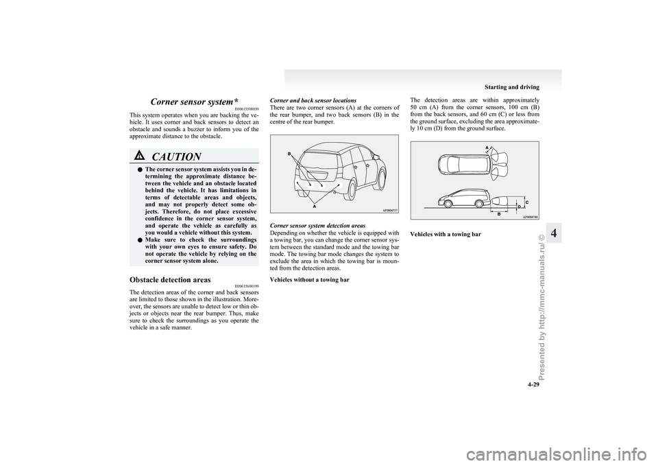
Obstacle detection areas E00615600199
The detection areas of the corner and back sensors
are
limited to those shown in the illustration. More-
over, the sensors are unable to detect low or thin ob-
jects or objects near the rear bumper. Thus, make
sure to check the surroundings as you operate the
vehicle in a safe manner. Corner and back sensor locations
There
are two corner sensors (A) at the corners of
the rear bumper, and two back sensors (B) in the
centre of the rear bumper. Corner sensor system detection areas
Depending
on whether the vehicle is equipped with
a towing bar, you can change the corner sensor sys-
tem between the standard mode and the towing bar
mode. The towing bar mode changes the system to
exclude the area in which the towing bar is moun-
ted from the detection areas.
Vehicles without a towing bar The detection areas are within approximately
50
cm (A) from the corner sensors, 100 cm (B)
from the back sensors, and 60 cm (C) or less from
the ground surface, excluding the area approximate-
ly 10 cm (D) from the ground surface. Vehicles with a towing bar Starting and driving
4-29 4
Presented by http://mmc-manuals.ru/ \251