warning light MITSUBISHI GRANDIS 2010 Owner's Manual (in English)
[x] Cancel search | Manufacturer: MITSUBISHI, Model Year: 2010, Model line: GRANDIS, Model: MITSUBISHI GRANDIS 2010Pages: 273, PDF Size: 21.01 MB
Page 5 of 273
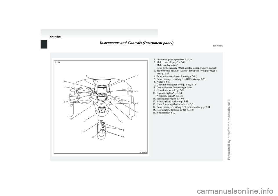
Instruments and Controls (Instrument panel)
E001001049131. Instrument panel upper box p. 5-39
2.
Multi centre display* p. 3-09Multi display station*
Refer to the separate “Multi display station owner’s manual”
3. Supplemental restraint system - airbag (for front passenger’s seat) p. 2-29
4. Front automatic air conditioning p. 5-05
5. Front passenger’s airbag ON-OFF switch p. 2-33
6. Audio p. 5-13
7. Gearshift or selector lever p. 4-13, 4-15
8. Cup holder (for front seats) p. 5-40
9. Heated seat switch* p. 2-06
10. Cigarette lighter* p. 5-34 Accessory socket* p. 5-35
11. Parking brake lever p. 4-04
12. Ashtray (fixed position) p. 5-33
13. Hazard warning flasher switch p. 3-21
14. Front passenger’s airbag OFF indication lamp p. 2-34
15. Rear window demister switch p. 3-25
16. Ventilators p. 5-02 OverviewLHD
1 2
3 4
5
6
7
8
9
10
1
1
12
13
14
15
16
Presented by http://mmc-manuals.ru/ \251
Page 21 of 273
Keys
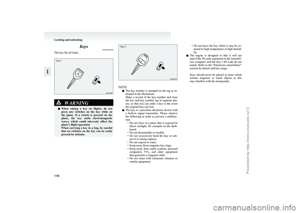
E00300102096
The key fits all locks.Type 1 WARNING
l When
taking a key on flights, do not
press any switches on the key while on
the plane. If a switch is pressed on the
plane, the key emits electromagnetic
waves, which could adversely affect the
plane’s flight operation.
When carrying a key in a bag, be careful
that no switches on the key can be easily
pressed by mistake.
Type 2 NOTE
l The
key number is stamped on the tag as in-
dicated in the illustration.
Make a record of the key number and store
the key and key number tag in separate pla-
ces, so that you can order a key in the event
the original keys are lost.
l The key is a precision electronic device with
a built-in signal transmitter. Please observe
the following in order to prevent a malfunc-
tion.
• Do not leave in a place that is exposed todirect sunlight, for example on the dash-
board.
• Do not disassemble or modify.
• Do not excessively bend the key or sub- ject it to strong impacts.
• Do not expose to water.
• Keep away from magnetic key rings.
• Keep away from audio systems, personal computers, TVs, and other equipment
that generates a magnetic field.
• Do not clean with ultrasonic cleaners or similar equipment. • Do
not leave the key where it may be ex-
posed to high temperature or high humid-
ity.
l The engine is designed so that it will not
start if the ID code registered in the immobil-
izer computer and the key’s ID code do not
match. Refer to the “Electronic immobilizer”
section for details and key usage.
Keys should never be placed in areas which
contain magnetic or metal objects as this
may interfere with the transponder. Locking and unlocking
1-02
1
Presented by http://mmc-manuals.ru/ \251
Page 30 of 273
CAUTION
l
Always keep the release lever lid on tail-
gate closed when driving so that your lug-
gage cannot accidentally bump against
the lever and open the tailgate. Electric window control
E00302200042
The electric windows can only be operated with the
ignition switch in the “ON” position.
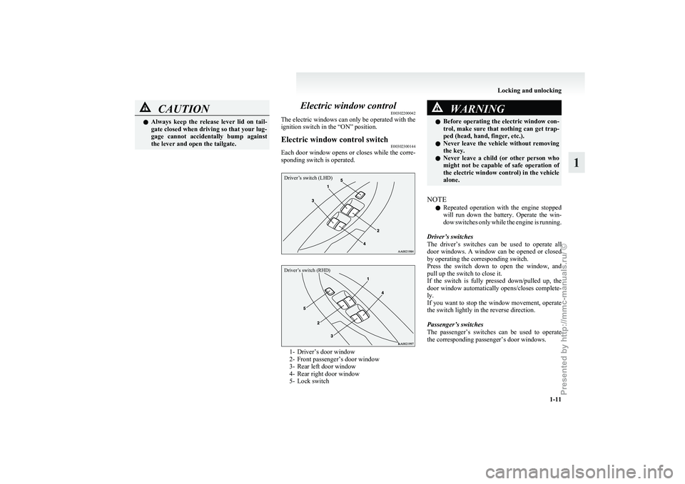
Electric window control switch E00302300144
Each door window opens or closes while the corre-
sponding switch is operated.
Driver’s switch (LHD)
Driver’s switch (RHD) 1- Driver’s door window
2-
Front passenger’s door window
3- Rear left door window
4- Rear right door window
5- Lock switch WARNING
l Before
operating the electric window con-
trol, make sure that nothing can get trap-
ped (head, hand, finger, etc.).
l Never leave the vehicle without removing
the key.
l Never leave a child (or other person who
might not be capable of safe operation of
the electric window control) in the vehicle
alone.
NOTE l Repeated
operation with the engine stopped
will run down the battery. Operate the win-
dow switches only while the engine is running.
Driver’s switches
The driver’s switches can be used to operate all
door windows. A window can be opened or closed
by operating the corresponding switch.
Press the switch down to open the window, and
pull up the switch to close it.
If the switch is fully pressed down/pulled up, the
door window automatically opens/closes complete-
ly.
If you want to stop the window movement, operate
the switch lightly in the reverse direction.
Passenger’s switches
The passenger’s switches can be used to operate
the corresponding passenger’s door windows. Locking and unlocking
1-11 1
Presented by http://mmc-manuals.ru/ \251
Page 42 of 273
CAUTION
l
Operate in the high position for quick heat-
ing. Once the seat is warm, set the heater
to low to keep it warm. Slight variations
in seat temperature may be felt while us-
ing the heated seats. This is caused by the
operation of the heater’s internal thermo-
stat and does not indicate a malfunction.
l If the following types of persons use the
heated seats, they might become too hot
or receive minor burns (red skin, heat blis-
ters, etc.):
• Children, elderly or ill people
• People with sensitive skin
• Excessively tired people
• People under the influence of alcoholor sleep inducing medication (cold
medicine, etc.)
l Do not use a blanket, cushion, or other ma-
terial with high heat insulation properties
on the seat while using the heater; this
might cause the heater element to overheat
l Turn the heater off immediately if it ap-
pears to be malfunctioning during use.
NOTE l Do
not place heavy objects on the seat or
stick pins, needles, or other pointed objects
into it.
l When cleaning the seat, do not use benzene,
kerosene, petrol, alcohol, or other organic sol-
vents; these might damage the surface of the
seat and also the heater element.
l If water or any other liquid is spilled on the
seat, allow it to dry thoroughly before attempt-
ing to use the heater. Second seat
E00402000227
When
a person is sitting in the middle seating posi-
tion of the second seat in a cabin with 7-person
seats, adjust the head restraints to heights at which
they lock in position. Refer to “Head restraints” on
page 2-11.
NOTE
l It is possible to adjust each side of the sec-
ond seats forward and backward independent-
ly of the other side, to adjust the seatback an-
gle independently on each side, and to fold
up the seat cushion independently on each
side.
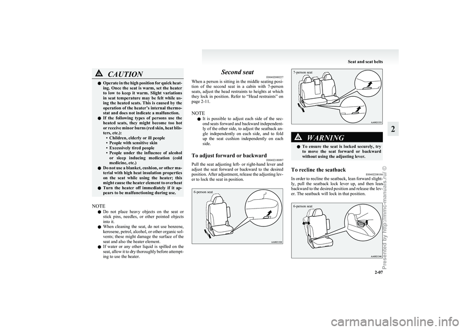
To adjust forward or backward E00402100097
Pull the seat adjusting left- or right-hand lever and
adjust
the seat forward or backward to the desired
position. After adjustment, release the adjusting lev-
er to lock the seat in position.
6-person seat
7-person seat WARNING
l To
ensure the seat is locked securely, try
to move the seat forward or backward
without using the adjusting lever.
To recline the seatback E00402200186
In order to recline the seatback, lean forward slight-
ly,
pull the seatback lock lever up, and then lean
backward to the desired position and release the lev-
er. The seatback will lock in that position.
6-person seat Seat and seat belts
2-07 2
Presented by http://mmc-manuals.ru/ \251
Page 46 of 273
CAUTION
l
The reclining mechanism of the seatback
is spring loaded, causing it to return to
the vertical position when the lock lever
is operated. When using the lever, sit
close to the seatback or hold it with your
hand to control its return motion.
Folding the seatbacks forward E00402900024
Larger objects can be loaded into the vehicle if a
seatback is folded forwards. WARNING
l The
luggage compartment in the rear of
the vehicle should never be used as a play
area by children. Children should be seat-
ed with seat belts fastened when the vehi-
cle is in motion. Be sure that the rear seat-
backs are returned to their fully upright
position and locked in place. CAUTION
l
Do
not stack luggage above the seatback
height. Secure the luggage firmly.
Otherwise, serious accidents could result
due to restricted rear vision or unrestrain-
ed objects entering the passenger compart-
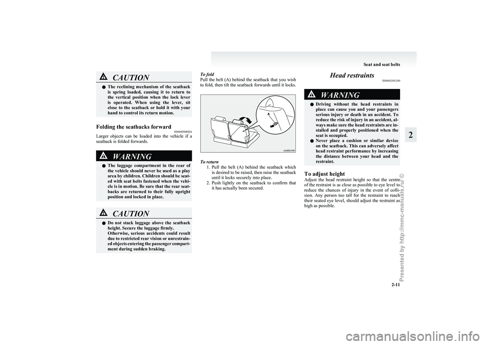
ment during sudden braking. To fold
Pull
the belt (A) behind the seatback that you wish
to fold, then tilt the seatback forwards until it locks. To return
1. Pull
the belt (A) behind the seatback which
is desired to be raised, then raise the seatback
until it locks securely into place.
2. Push lightly on the seatback to confirm that it has actually been secured. Head restraints
E00403301240 WARNING
l Driving
without the head restraints in
place can cause you and your passengers
serious injury or death in an accident. To
reduce the risk of injury in an accident, al-
ways make sure the head restraints are in-
stalled and properly positioned when the
seat is occupied.
l Never place a cushion or similar device
on the seatback. This can adversely affect
head restraint performance by increasing
the distance between your head and the
restraint.
To adjust height
Adjust
the head restraint height so that the centre
of the restraint is as close as possible to eye level to
reduce the chances of injury in the event of colli-
sion. Any person too tall for the restraint to reach
their seated eye level, should adjust the restraint as
high as possible. Seat and seat belts
2-11 2
Presented by http://mmc-manuals.ru/ \251
Page 49 of 273
CAUTION
l
When stowing the seat, hold it with your
hands and lower it slowly. Unless you
hold the seat securely, it may suddenly tip
under its own weight, trapping your
hands.
l Do not pull the belt while a person is sit-
ting on the seat. The seat could tip back-
ward, resulting in an accident.
NOTE l The
removed third seat head restraints (C)
can be fitted together and stored in the cargo
net in the luggage area. (Refer to “Cargo net”
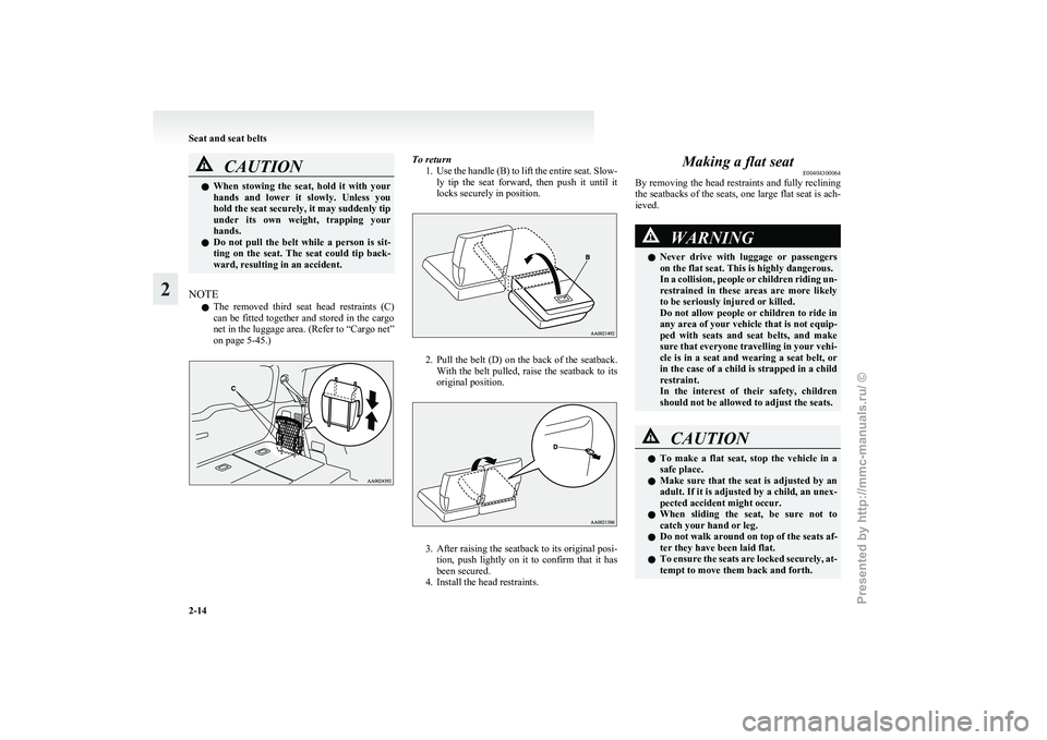
on page 5-45.) To return
1. Use
the handle (B) to lift the entire seat. Slow-
ly tip the seat forward, then push it until it
locks securely in position. 2. Pull
the belt (D) on the back of the seatback.
With the belt pulled, raise the seatback to its
original position. 3. After
raising the seatback to its original posi-
tion, push lightly on it to confirm that it has
been secured.
4. Install the head restraints. Making a flat seat
E00404300064
By
removing the head restraints and fully reclining
the seatbacks of the seats, one large flat seat is ach-
ieved. WARNING
l Never
drive with luggage or passengers
on the flat seat. This is highly dangerous.
In a collision, people or children riding un-
restrained in these areas are more likely
to be seriously injured or killed.
Do not allow people or children to ride in
any area of your vehicle that is not equip-
ped with seats and seat belts, and make
sure that everyone travelling in your vehi-
cle is in a seat and wearing a seat belt, or
in the case of a child is strapped in a child
restraint.
In the interest of their safety, children
should not be allowed to adjust the seats. CAUTION
l
To
make a flat seat, stop the vehicle in a
safe place.
l Make sure that the seat is adjusted by an
adult. If it is adjusted by a child, an unex-
pected accident might occur.
l When sliding the seat, be sure not to
catch your hand or leg.
l Do not walk around on top of the seats af-
ter they have been laid flat.
l To ensure the seats are locked securely, at-
tempt to move them back and forth. Seat and seat belts
2-14
2
Presented by http://mmc-manuals.ru/ \251
Page 53 of 273
WARNING
l No modifications or additions should be
made by the user which will either pre-
vent the seat belt adjusting devices from
operating to remove slack, or prevent the
seat belt assembly from being adjusted to
remove slack.
l To reduce risk of serious or fatal injury
in an accident, including the deploying
driver airbag, the driver should adjust
the driver’s seat to the rear most position
that still allows good visibility and good
control of the steering wheel, the brake
and accelerator, and vehicle controls.
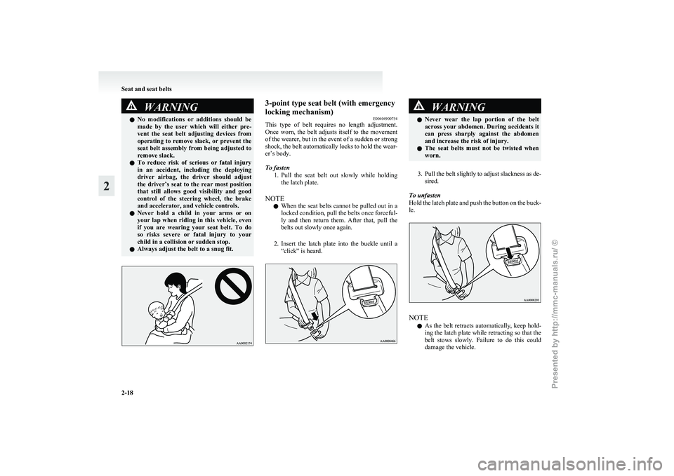
l Never hold a child in your arms or on
your lap when riding in this vehicle, even
if you are wearing your seat belt. To do
so risks severe or fatal injury to your
child in a collision or sudden stop.
l Always adjust the belt to a snug fit. 3-point type seat belt (with emergency
locking mechanism)
E00404900754
This
type of belt requires no length adjustment.
Once worn, the belt adjusts itself to the movement
of the wearer, but in the event of a sudden or strong
shock, the belt automatically locks to hold the wear-
er’s body.
To fasten
1. Pull the seat belt out slowly while holdingthe latch plate.
NOTE l When the seat belts cannot be pulled out in a
locked condition, pull the belts once forceful-
ly and then return them. After that, pull the
belts out slowly once again.
2. Insert the latch plate into the buckle until a “click” is heard. WARNING
l Never
wear the lap portion of the belt
across your abdomen. During accidents it
can press sharply against the abdomen
and increase the risk of injury.
l The seat belts must not be twisted when
worn.
3. Pull
the belt slightly to adjust slackness as de- sired.
To unfasten
Hold the latch plate and push the button on the buck-
le. NOTE
l As
the belt retracts automatically, keep hold-
ing the latch plate while retracting so that the
belt stows slowly. Failure to do this could
damage the vehicle. Seat and seat belts
2-18
2
Presented by http://mmc-manuals.ru/ \251
Page 67 of 273
WARNING
l Extreme Hazard!
Do
not use a rearward facing child re-
straint on a seat protected by an airbag in
front of it! How the Supplemental Restraint Sys-
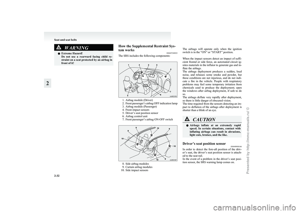
tem works
E00407300935
The SRS includes the following components: 1. Airbag module (Driver)
2. Front
passenger’s airbag OFF indication lamp
3. Airbag module (Passenger)
4. Front impact sensors
5. Driver’s seat position sensor
6. Airbag control unit
7. Front passenger’s airbag ON-OFF switch 8. Side airbag modules
9.
Curtain airbag modules
10. Side impact sensors
The
airbags will operate only when the ignition
switch is in the “ON” or “START” position.
When the impact sensors detect an impact of suffi-
cient frontal or side force, an automated circuit ig-
nites materials in the inflator to generate gas and in-
flate the airbags.
The airbags deployment produces a sudden, loud
noise, and releases some smoke and powder, but
these conditions are not injurious, and do not indi-
cate a fire in the vehicle. People with respiratory
problems may feel some temporary irritation from
chemicals used to produce the deployment; open
the windows after airbag deployment, if safe to do
so.
The airbags deflate very rapidly after deployment,
so there is little danger of obscured vision.
The time required from the sensors detecting an im-
pact to deflation of the airbags after deployment is
shorter than a blink of an eye. CAUTION
l
Airbags
inflate at an extremely rapid
speed. In certain situations, contact with
inflating airbags can result in abrasions,
light cuts, bruises, and the like.
Driver’s seat position sensor E00409900166
In order to detect the fore-aft position of the driv-
er’s
seat, the driver’s seat position sensor is attach-
ed to the seat rail.
In the event of a problem in the driver’s seat posi-
tion sensor, the SRS warning lamp comes on. Seat and seat belts
2-32
2
Presented by http://mmc-manuals.ru/ \251
Page 81 of 273
Low fuel warning lamp
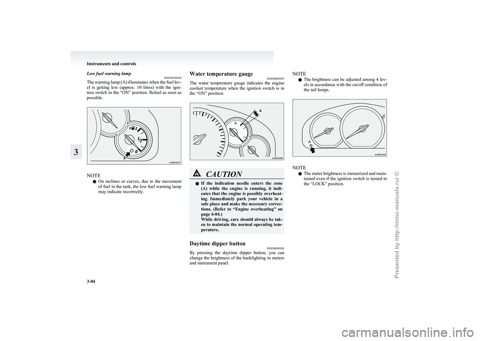
E00508100638
The
warning lamp (A) illuminates when the fuel lev-
el is getting low (approx. 10 litres) with the igni-
tion switch in the “ON” position. Refuel as soon as
possible. NOTE
l On
inclines or curves, due to the movement
of fuel in the tank, the low fuel warning lamp
may indicate incorrectly. Water temperature gauge
E00500800495
The
water temperature gauge indicates the engine
coolant temperature when the ignition switch is in
the “ON” position. CAUTION
l
If
the indication needle enters the zone
(A) while the engine is running, it indi-
cates that the engine is possibly overheat-
ing. Immediately park your vehicle in a
safe place and make the necessary correc-
tions. (Refer to “Engine overheating” on
page 6-04.)
While driving, care should always be tak-
en to maintain the normal operating tem-
perature.
Daytime dipper button E00508800026
By pressing the daytime dipper button, you can
change
the brightness of the backlighting in meters
and instrument panel. NOTE
l The
brightness can be adjusted among 4 lev-
els in accordance with the on/off condition of
the tail lamps. NOTE
l The
meter brightness is memorized and main-
tained even if the ignition switch is turned to
the “LOCK” position. Instruments and controls
3-04
3
Presented by http://mmc-manuals.ru/ \251
Page 98 of 273
Turn/Lane-change signals
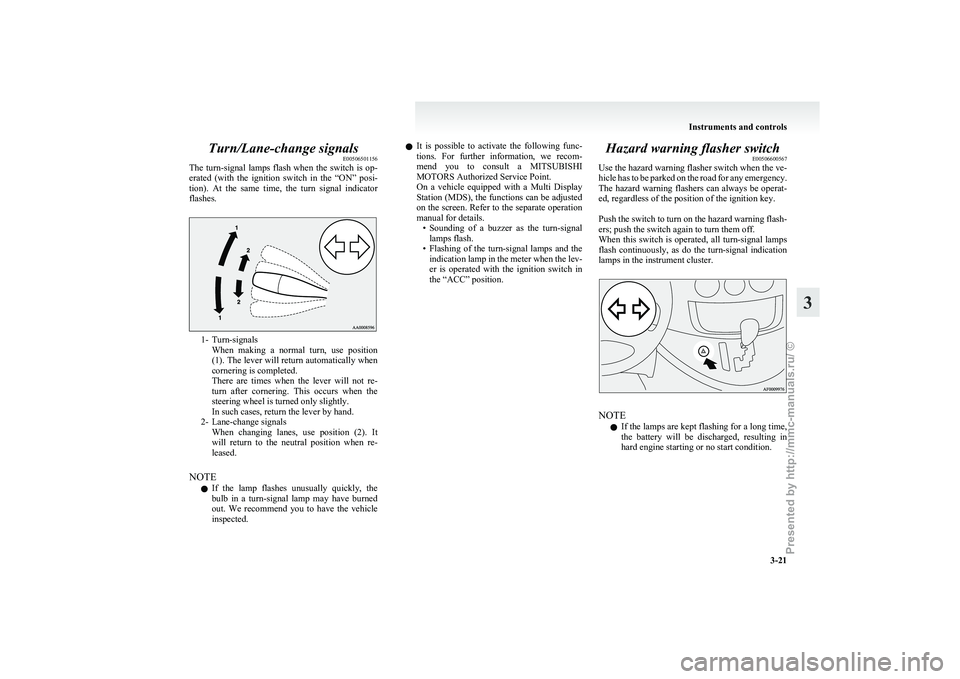
E00506501156
The
turn-signal lamps flash when the switch is op-
erated (with the ignition switch in the “ON” posi-
tion). At the same time, the turn signal indicator
flashes. 1- Turn-signals
When
making a normal turn, use position
(1). The lever will return automatically when
cornering is completed.
There are times when the lever will not re-
turn after cornering. This occurs when the
steering wheel is turned only slightly.
In such cases, return the lever by hand.
2- Lane-change signals When changing lanes, use position (2). It
will return to the neutral position when re-
leased.
NOTE l If the lamp flashes unusually quickly, the
bulb in a turn-signal lamp may have burned
out. We recommend you to have the vehicle
inspected. l
It
is possible to activate the following func-
tions. For further information, we recom-
mend you to consult a MITSUBISHI
MOTORS Authorized Service Point.
On a vehicle equipped with a Multi Display
Station (MDS), the functions can be adjusted
on the screen. Refer to the separate operation
manual for details. • Sounding of a buzzer as the turn-signallamps flash.
• Flashing of the turn-signal lamps and the indication lamp in the meter when the lev-
er is operated with the ignition switch in
the “ACC” position. Hazard warning flasher switch
E00506600567
Use
the hazard warning flasher switch when the ve-
hicle has to be parked on the road for any emergency.
The hazard warning flashers can always be operat-
ed, regardless of the position of the ignition key.
Push the switch to turn on the hazard warning flash-
ers; push the switch again to turn them off.
When this switch is operated, all turn-signal lamps
flash continuously, as do the turn-signal indication
lamps in the instrument cluster. NOTE
l If
the lamps are kept flashing for a long time,
the battery will be discharged, resulting in
hard engine starting or no start condition. Instruments and controls
3-21 3
Presented by http://mmc-manuals.ru/ \251