stop start MITSUBISHI I-MIEV 2011 User Guide
[x] Cancel search | Manufacturer: MITSUBISHI, Model Year: 2011, Model line: I-MIEV, Model: MITSUBISHI I-MIEV 2011Pages: 193, PDF Size: 12.2 MB
Page 102 of 193
WARNING
l Do not leave any objects near the brake
pedal or let a floor mat slide under it; do-
ing so could prevent the full pedal stroke
that would be necessary in an emergency.
Make sure that the pedal can be operated
freely at all times. Make sure the floor
mat is securely held in place.
Brake pad and linings l Avoid hard braking situations.
New
brakes need to be broken-in by moder-
ate use for the first 200 km (125 miles).
l The disc brakes are provided with a warning
device which emits a shrieking metallic
sound while braking if the brake pads have
reached their wear limit. If you hear this
sound, have the brake pads replaced immedi-
ately. WARNING
l Driving
with worn brake pads will make
it harder to stop, and can cause an acci-
dent. Brake assist system
E00627000174
The brake assist system is a device assisting drivers
who
cannot depress the brake pedal firmly when it
is necessary to do so (such as in emergency stop sit-
uations) and provides greater braking force.
If the brake pedal is depressed suddenly, the brakes
will be applied with more force than usual. CAUTION
l
The
brake assist system is not a device de-
signed to exercise braking force greater
than its capacity. Make sure to always
keep a sufficient distance between vehi-
cles in front of you without relying too
much on the brake assist system.
NOTE l Once
the brake assist system is operational,
it maintains great braking force even if the
brake pedal is lightly released.
To stop its operation, completely remove
your foot from the brake pedal.
l The brake assist system may become opera-
tional when the brake pedal is fully de-
pressed even if it has not been depressed sud-
denly. l
When
the brake assist system is in use, you
may feel as if the depressed brake pedal is
soft, the pedal moves in small motions in con-
junction with the sound of the ABS opera-
tion, or the vehicle body and the steering
wheel vibrate. This occurs when the brake as-
sist system is operating normally and does
not indicate faulty operation. Continue to
firmly depress the brake pedal.
l You may hear an operation noise when the
brake pedal is depressed suddenly while sta-
tionary. This does not indicate a malfunction
and the brake assist system is operating nor-
mally. Starting and driving
5-13 5
Presented by http://mmc-manuals.ru/ \251
Page 103 of 193
Anti-lock brake system (ABS)
E00607101394
The
anti-lock brake system (ABS) helps prevent
the wheels from locking during braking. This helps
maintain vehicle drivability and steering wheel han-
dling.
Driving hints
l Always keep a safe distance from the vehicle
in front of you. Even if your vehicle is equip-
ped with ABS, leave a greater braking dis-
tance when:
• Driving on gravel or snow-covered roads.
• Driving with tyre chains installed.
• Driving on uneven road surfaces.
l Operation of ABS is not restricted to situa-
tions where brakes are applied suddenly.
This system may also prevent the wheels
from locking when you drive over manholes,
steel roadwork plates, road markings, or any
uneven road surface.
l When the ABS is activated, you may feel the
brake pedal pulsation and the vibrations of
the vehicle body and steering wheel. It may
also feel as if the pedal resists being pressed.
In this situation, simply hold the brake ped-
al down firmly. Do not pump the brake,
which will result in reduced braking per-
formance.
l An operation noise may be emitted from the
bonnet room in the following situations. The
sound is associated with checking the opera-
tions of the anti-lock brake system.
At this time, you may feel a shock from the
brake pedal if you depress it. These do not in-
dicate a malfunction.
• When the electric motor switch is turnedto the “ON” position. • When the vehicle is driven for a while af-
ter the electric motor is turned on.
l The ABS can be used after the vehicle has
reached a speed over approximately 10 km/h
(6 mph). It stops working when the vehicle
slows below approximately 5 km/h (3 mph). CAUTION
l
The
ABS cannot prevent accidents. It is
your responsibility to take safety precau-
tions and to drive carefully.
l To prevent failure of the ABS, be sure
wheels and tyres are of the specified size
and the same type.
l Do not install any aftermarket limited-
slip differential (LSD) on your vehicle.
The ABS may stop functioning properly.
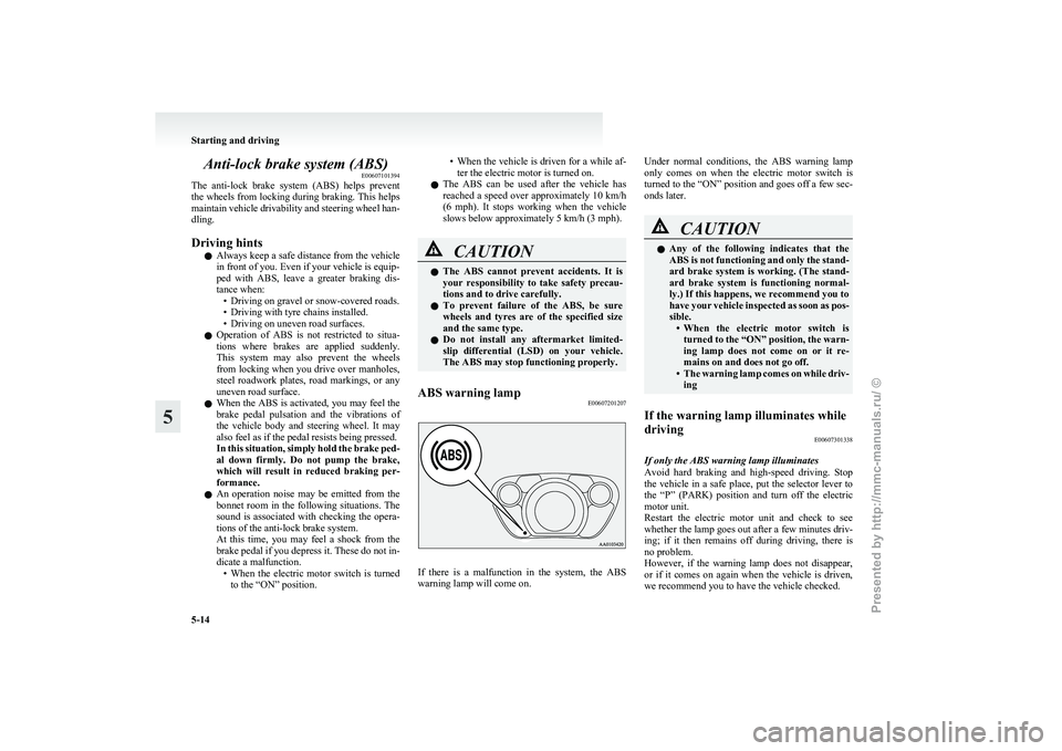
ABS warning lamp E00607201207 If there is a malfunction in the system, the ABS
warning lamp will come on.Under normal conditions, the ABS warning lamp
only
comes on when the electric motor switch is
turned to the “ON” position and goes off a few sec-
onds later. CAUTION
l
Any
of the following indicates that the
ABS is not functioning and only the stand-
ard brake system is working. (The stand-
ard brake system is functioning normal-
ly.) If this happens, we recommend you to
have your vehicle inspected as soon as pos-
sible. • When the electric motor switch isturned to the “ON” position, the warn-
ing lamp does not come on or it re-
mains on and does not go off.
• The warning lamp comes on while driv- ing
If the warning lamp illuminates while
driving E00607301338
If only the ABS warning lamp illuminates
Avoid
hard braking and high-speed driving. Stop
the vehicle in a safe place, put the selector lever to
the “P” (PARK) position and turn off the electric
motor unit.
Restart the electric motor unit and check to see
whether the lamp goes out after a few minutes driv-
ing; if it then remains off during driving, there is
no problem.
However, if the warning lamp does not disappear,
or if it comes on again when the vehicle is driven,
we recommend you to have the vehicle checked. Starting and driving
5-14
5
Presented by http://mmc-manuals.ru/ \251
Page 104 of 193
If the ABS warning lamp and brake warning
lamp illuminate at the same time
The
ABS and brake force distribution function may
not work, so hard braking could make the vehicle
unstable.
Avoid hard braking and high-speed driving. Stop
the vehicle in a safe place and we recommend you
to have it checked.
NOTE
l The warning lamp may be illuminated when
the electric motor unit is started while the aux-
iliary battery voltage is low, but this is not an
ABS malfunction.
When the traction battery is charged, the aux-
iliary battery is charged at the same time, and
the warning lamp will go out.
If the warning lamp does not go out or illumi-
nates from time to time even after the battery
is charged, have the vehicle inspected at a
MITSUBISHI MOTORS Authorized Service
Point. After driving on icy roads
E00618800176
After
driving on snowy or icy roads, remove any
snow and ice which may have be left around the
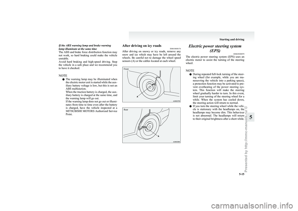
wheels. Be careful not to damage the wheel speed
sensors (A) or the cables located at each wheel.
Front
Rear Electric power steering system
(EPS) E00629200079
The
electric power steering system (EPS) uses an
electric motor to assist the turning of the steering
wheel.
NOTE
l During repeated full-lock turning of the steer-
ing wheel (for example, while you are ma-
noeuvring the vehicle into a parking space),
a protection function may be activated to pre-
vent overheating of the power steering sys-
tem. This function will make the steering
wheel gradually harder to turn. In this event,
limit your turning of the steering wheel for a
while. When the system has cooled down,
the steering action will return to normal.
l If you turn the steering wheel while the vehi-
cle is stationary with the headlamps on, the
headlamps may become dim. This behaviour
is not abnormal. The headlamps will return
to their original brightness after a short while. Starting and driving
5-15 5
Presented by http://mmc-manuals.ru/ \251
Page 105 of 193
Electric power steering system warn-
ing lampType 1
Type 2
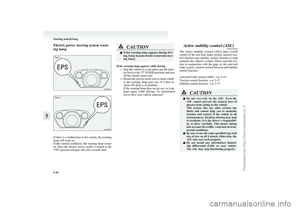
If there is a malfunction in the system, the warning
lamp will come on.
Under
normal conditions, the warning lamp comes
on when the electric motor switch is turned to the
“ON” position and goes off a few seconds later. CAUTION
l
If
the warning lamp appears during driv-
ing, it may become harder to turn the steer-
ing wheel.
If the warning lamp appears while driving 1.
Stop the vehicle in a safe place, put the selec-tor lever to the “P” (PARK) position and turn
off the electric motor unit.
2. Restart the electric motor unit to check wheth- er the warning lamp goes out; if it then re-
mains off, there is no problem.
If the warning lamp does not go out, or it ap-
pears again while driving, we recommend
you to have your vehicle inspected. Active stability control (ASC)
E00616700386
The
Active Stability Control (ASC) takes overall
control of the anti-lock brake system, traction con-
trol function and stability control function to help
maintain the vehicle’s control. Please read this sec-
tion in conjunction with the page on the anti-lock
brake system, traction control function and stability
control function.
Anti-lock brake system (ABS) ® p. 5-14
Traction control function ® p. 5-17
Stability control function ® p. 5-17 CAUTION
l
Do
not over-rely on the ASC. Even the
ASC cannot prevent the natural laws of
physics from acting on the vehicle.
This system, like any other system, has
limits and cannot help you to maintain
traction and control of the vehicle in all
circumstances. Reckless driving may lead
to accidents. It is the driver’s responsibil-
ity to drive carefully. This means taking
into account the traffic, road and environ-
mental conditions.
l Be sure to use the same specified type and
size of tyre on all 4 wheels. Otherwise, the
ASC may not work properly.
l Do not install any aftermarket limited-
slip differential (LSD) on your vehicle.
The ASC may stop functioning properly. Starting and driving
5-16
5
Presented by http://mmc-manuals.ru/ \251
Page 106 of 193
NOTE
l An
operation noise may be emitted from the
bonnet room in the following situations. The
sound is associated with checking the opera-
tions of the ASC. At this time, you may feel
a shock from the brake pedal if you depress
it. These do not indicate a malfunction. • When the electric motor switch is turnedto the “ON” position.
• When the vehicle is driven for a while af- ter the electric motor is turned on.
l When the ASC is activated, you may feel a
vibration in the vehicle body or hear a whin-
ing sound from the bonnet room.
This indicates that the system is operating nor-
mally. It does not indicate a malfunction.
l When the anti-lock brake system warning
lamp is illuminated, the ASC is not active.
Traction control function E00619000087
On slippery surfaces, the traction control function
prevents
the drive wheels from spinning excessive-
ly, thus helping the vehicle to start moving from a
stopped condition. It also provides sufficient driv-
ing force and steering performance as the vehicle
turns while pressing the acceleration pedal. CAUTION
l
When
driving a vehicle on a snowy or icy
road, be sure to install snow tyres and
drive the vehicle at moderate speeds. Stability control function
E00619100088
The
stability control function is designed to help
the driver maintain control of the vehicle on slip-
pery roads or during rapid steering manoeuvres. It
works by controlling the electric motor unit output
and the brake on each wheel.
NOTE
l The stability control function operates at
speeds of about 15 km/h (9 mph) or higher.
“ASC OFF” switch E00619200496
The ASC is automatically activated when the elec-
tric
motor switch is turned to the “ON” position.
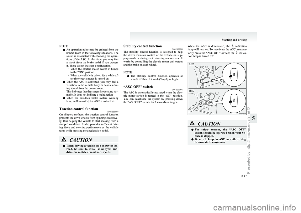
You can deactivate the system by pressing down
the “ASC OFF” switch for 3 seconds or longer. When the ASC is deactivated, the indication
lamp
will turn on. To reactivate the ASC, momen-
tarily press the “ASC OFF” switch; the indica-
tion lamp is turned off. CAUTION
l
For
safety reasons, the “ASC OFF”
switch should be operated when your ve-
hicle is stopped.
l Be sure to keep the ASC on while driving
in normal circumstances. Starting and driving
5-17 5
Presented by http://mmc-manuals.ru/ \251
Page 107 of 193
NOTE
l When
moving out of mud, sand or fresh
snow, pressing the accelerator pedal may not
allow the electric motor speed to increase. In
such situations, temporarily turning off the
ASC with the “ASC OFF” switch will make
it easier to move out your vehicle.
l Using the “ASC OFF” switch turns off both
the stability control function and the traction
control function.
l If you continue to press the “ASC OFF”
switch after the ASC is turned off, the “mis-
taken operation protection function” will ac-
tivate and the ASC will turn back on.
ASC indication lamp or ASC OFF in-
dication lamp E00619300556-
ASC indication lamp
The indication lamp will blink
when the ASC is operating. -
ASC OFF indication lamp
This indication lamp will turn on
when the ASC is turned off with the
“ASC OFF” switch. CAUTION
l
When
the indication lamp blinks, ASC
is
operating, which means that the road is
slippery or that your vehicle’s wheels are
beginning to slip. If this happens, drive
slower with less accelerator input. If the indication lamp illuminates
while driving
E00631100017
If
an abnormal condition occurs in the system, the indication lamp and indication lamp will turn
on. CAUTION
l
The system may be malfunctioning.
Stop
the vehicle in a safe place, put the se-
lector lever to the “P” (PARK) position
and turn off the electric motor unit.
Restart the electric motor unit and check
whether the indication lamp goes out. If
they go out, there is no abnormal condi-
tion. If they do not go out or appear fre-
quently, it is not necessary to stop the ve-
hicle immediately, but we recommend
you to have your vehicle inspected. Towing
E00624400089 CAUTION
l
When
towing the vehicle with only the
front wheels raised off the ground, do not
place the electric motor switch in the
“ON” position. Placing the electric motor
switch in the “ON” position could cause
the ASC to operate, resulting in an acci-
dent.
Note that the correct towing method de-
pends on the vehicle’s drive configura-
tion. For details, refer to “Towing” on
page 7-10. Starting and driving
5-18
5
Presented by http://mmc-manuals.ru/ \251
Page 128 of 193
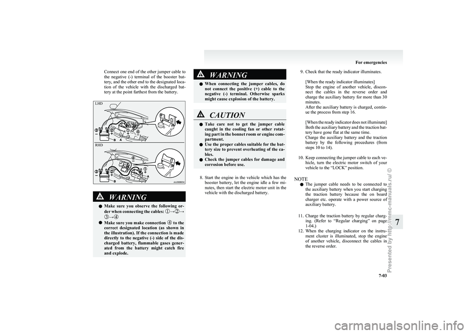
Connect one end of the other jumper cable to
the
negative (-) terminal of the booster bat-
tery, and the other end to the designated loca-
tion of the vehicle with the discharged bat-
tery at the point farthest from the battery. WARNING
l Make
sure you observe the following or-
der when connecting the cables: → →
→
l
Make sure you make connection to the
correct
designated location (as shown in
the illustration). If the connection is made
directly to the negative (-) side of the dis-
charged battery, flammable gases gener-
ated from the battery might catch fire
and explode. WARNING
l When
connecting the jumper cables, do
not connect the positive (+) cable to the
negative (-) terminal. Otherwise sparks
might cause explosion of the battery. CAUTION
l
Take
care not to get the jumper cable
caught in the cooling fan or other rotat-
ing part in the bonnet room or engine com-
partment.
l Use the proper cables suitable for the bat-
tery size to prevent overheating of the ca-
bles.
l Check the jumper cables for damage and
corrosion before use.
8. Start
the engine in the vehicle which has the booster battery, let the engine idle a few mi-
nutes, then start the electric motor unit in the
vehicle with the discharged battery.
9. Check that the ready indicator illuminates.
[When the ready indicator illuminates]
Stop
the engine of another vehicle, discon-
nect the cables in the reverse order and
charge the auxiliary battery for more than 30
minutes.
After the auxiliary battery is charged, contin-
ue the process from step 16.
[When the ready indicator does not illuminate]
Both the auxiliary battery and the traction bat-
tery have gone flat at the same time.
Charge the auxiliary battery and the traction
battery by the following procedures (from
steps 10 to 14).
10. Keep connecting the jumper cable to each ve- hicle, turn the electric motor switch of your
vehicle to the “LOCK” position.
NOTE l The jumper cable needs to be connected to
the auxiliary battery when you start charging
the traction battery because the on board
charger etc. operate with a power source of
auxiliary battery.
11. Charge the traction battery by regular charg- ing. (Refer to “Regular charging” on page
1-04.)
12. When the charging indicator on the instru- ment cluster is illuminated, stop the engine
of another vehicle, disconnect the cables in
the reverse order. For emergencies
7-03 7LHD
RH
D
Presented by http://mmc-manuals.ru/ \251
Page 137 of 193
CAUTION
l
The person in the vehicle being towed
must pay attention to the brake lamps of
the towing vehicle and make sure the
rope never becomes slack.
l Avoid sudden braking, sudden accelera-
tion and sharp turning; such operation
could cause damage to the towing hooks
or the tow rope.
People in the vicinity could be injured as
a result.
l When towing or being towed down a long
slope, the brakes may overheat reducing
the effectiveness. In this situation, have
your vehicle transported by a tow truck.
l When the vehicle is to be towed by anoth-
er vehicle with all wheels on the ground,
make sure that the towing speed and dis-
tance given below are never exceeded,
causing damage to the transmission.
Towing speed: 30 km/h (19 mph)
Towing distance: 30 km (19 miles)
For the towing speed and the towing dis-
tance, follow the local driving laws and
regulations.
Towing another vehicle
Your
vehicle cannot be used to tow another vehicle. Operation under adverse driving
conditions E00801702717
On a flooded road l Do
not drive on a flooded road. If you drive
on a flooded road, not only the electric motor
unit stops but also a failure like electric leak-
age or short circuit may occur.
If you inevitably had to run on a flooded
road and the vehicle was exposed to water,
be sure to have your vehicle inspected by a
MITSUBISHI MOTORS Authorized Service
Point.
l If there is water on the brakes after driving
through puddles or washing the vehicle, re-
sulting in temporarily ineffective brakes. In
such cases, lightly depress the brake pedal to
see if the brakes operate properly. If they do
not, lightly depress the pedal several times
while driving in order to dry the brake pads.
l When driving in rain or on a road with many
puddles a layer of water may form between
the tyres and the road surface.
This reduces a tyre’s frictional resistance on
the road, resulting in loss of steering stability
and braking capability.
To cope with this, observe the following items:
(a) Drive your vehicle at slow speed.
(b) Do not drive on worn tyres.
(c) Always maintain the specified tyre inflation pressures. On a snow-covered or frozen road
l When
driving on a snow-covered or frozen
road, it is recommended that you use snow
tyres or tyre chains.
Refer to the “Snow tyres” and “Tyre chains”
sections.
l Avoid high-speed driving, sudden accelera-
tion, sudden braking, and sharp turns.
l Depressing the brake pedal during travel on
snowy or icy roads may cause tyre slippage
and skidding. Tyres may slip if the ability of
the tyres to grip the road surface lessens.
This may make it more difficult to stop the
vehicle with normal braking operations. For
vehicles with an anti-lock brake system
(ABS), firmly depress and hold down the
brake pedal.
l Allow extra distance between your vehicle
and the vehicle in front of you, and avoid sud-
den braking.
l Accumulation of ice on the braking system
can cause the wheels to lock. Pull away from
a standstill slowly after confirming safety
around the vehicle. CAUTION
l
Do
not press the accelerator pedal rapid-
ly. If the wheels break free of the ice, the
vehicle could suddenly start moving and
possibly cause an accident.
On a bumpy or rutted road
Drive
as slow as possible when driving on bumpy
or rutted roads. For emergencies
7-12
7
Presented by http://mmc-manuals.ru/ \251
Page 152 of 193
During cold weather
E08402600014
The
capacity of the auxiliary battery is reduced at
low temperatures. This is an inevitable result of its
chemical and physical properties. This is why a
very cold auxiliary battery, particularly one that is
not fully charged will only deliver a fraction of the
starting current which is normally available.
We recommend you to have the auxiliary battery
checked before the start of cold weather and, if nec-
essary, have it charged or replaced.
This does not only ensure reliable starting, but an
auxiliary battery which is kept fully charged also
has a longer life.
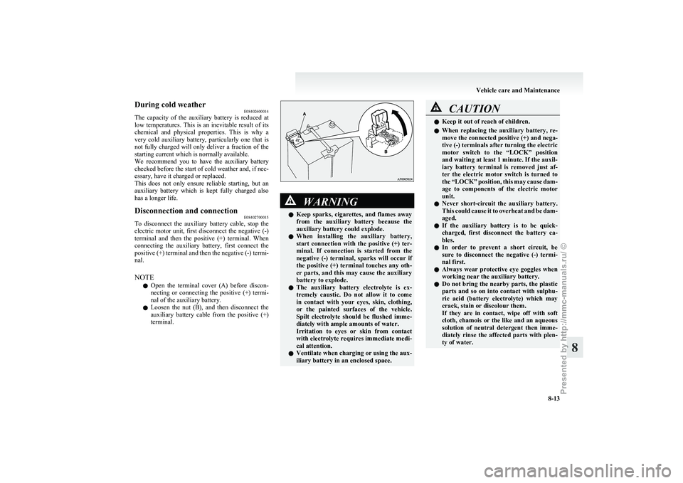
Disconnection and connection E08402700015
To disconnect the auxiliary battery cable, stop the
electric
motor unit, first disconnect the negative (-)
terminal and then the positive (+) terminal. When
connecting the auxiliary battery, first connect the
positive (+) terminal and then the negative (-) termi-
nal.
NOTE
l Open the terminal cover (A) before discon-
necting or connecting the positive (+) termi-
nal of the auxiliary battery.
l Loosen the nut (B), and then disconnect the
auxiliary battery cable from the positive (+)
terminal. WARNING
l Keep sparks, cigarettes, and flames away
from the auxiliary battery because the
auxiliary battery could explode.
l When installing the auxiliary battery,
start connection with the positive (+) ter-
minal. If connection is started from the
negative (-) terminal, sparks will occur if
the positive (+) terminal touches any oth-
er parts, and this may cause the auxiliary
battery to explode.
l The auxiliary battery electrolyte is ex-
tremely caustic. Do not allow it to come
in contact with your eyes, skin, clothing,
or the painted surfaces of the vehicle.
Spilt electrolyte should be flushed imme-
diately with ample amounts of water.
Irritation to eyes or skin from contact
with electrolyte requires immediate medi-
cal attention.
l Ventilate when charging or using the aux-
iliary battery in an enclosed space. CAUTION
l
Keep it out of reach of children.
l When
replacing the auxiliary battery, re-
move the connected positive (+) and nega-
tive (-) terminals after turning the electric
motor switch to the “LOCK” position
and waiting at least 1 minute. If the auxil-
iary battery terminal is removed just af-
ter the electric motor switch is turned to
the “LOCK” position, this may cause dam-
age to components of the electric motor
unit.
l Never short-circuit the auxiliary battery.
This could cause it to overheat and be dam-
aged.
l If the auxiliary battery is to be quick-
charged, first disconnect the battery ca-
bles.
l In order to prevent a short circuit, be
sure to disconnect the negative (-) termi-
nal first.
l Always wear protective eye goggles when
working near the auxiliary battery.
l Do not bring the nearby parts, the plastic
parts and so on into contact with sulphu-
ric acid (battery electrolyte) which may
crack, stain or discolour them.
If they are in contact, wipe off with soft
cloth, chamois or the like and an aqueous
solution of neutral detergent then imme-
diately rinse the affected parts with plen-
ty of water. Vehicle care and Maintenance
8-13 8
Presented by http://mmc-manuals.ru/ \251
Page 157 of 193
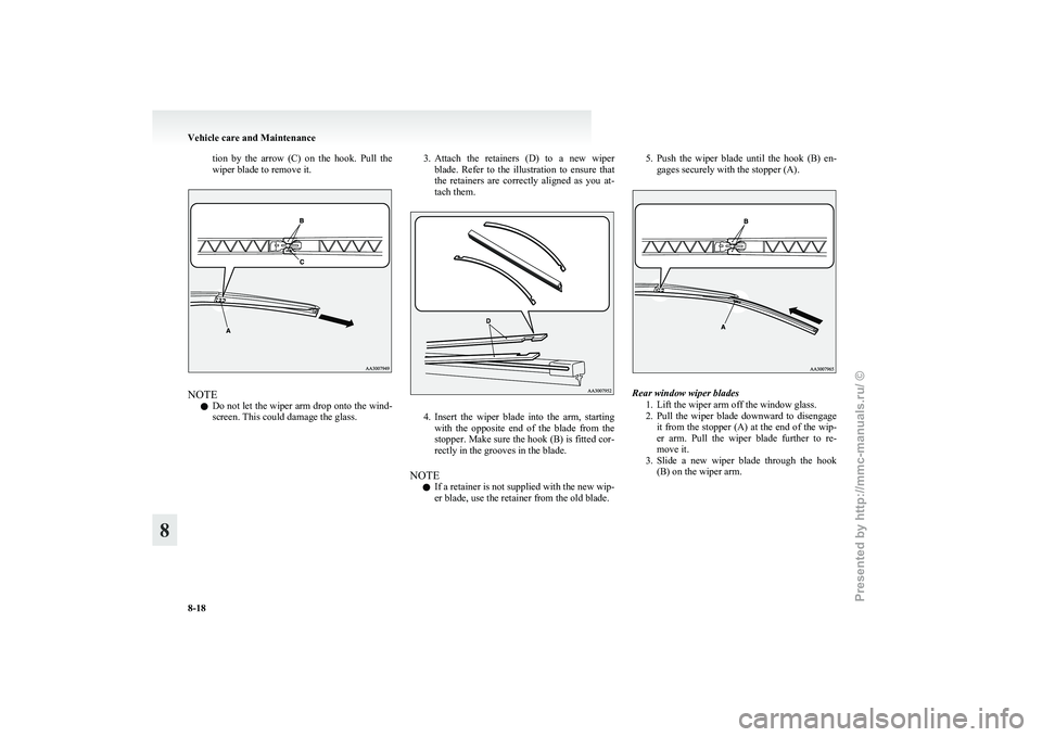
tion by the arrow (C) on the hook. Pull the
wiper blade to remove it.
NOTE
l Do
not let the wiper arm drop onto the wind-
screen. This could damage the glass. 3. Attach
the retainers (D) to a new wiper
blade. Refer to the illustration to ensure that
the retainers are correctly aligned as you at-
tach them. 4. Insert
the wiper blade into the arm, starting
with the opposite end of the blade from the
stopper. Make sure the hook (B) is fitted cor-
rectly in the grooves in the blade.
NOTE l If a retainer is not supplied with the new wip-
er blade, use the retainer from the old blade. 5. Push
the wiper blade until the hook (B) en-
gages securely with the stopper (A). Rear window wiper blades
1.
Lift the wiper arm off the window glass.
2. Pull the wiper blade downward to disengage it from the stopper (A) at the end of the wip-
er arm. Pull the wiper blade further to re-
move it.
3. Slide a new wiper blade through the hook (B) on the wiper arm. Vehicle care and Maintenance
8-18
8
Presented by http://mmc-manuals.ru/ \251