light MITSUBISHI I-MIEV 2011 Owners Manual
[x] Cancel search | Manufacturer: MITSUBISHI, Model Year: 2011, Model line: I-MIEV, Model: MITSUBISHI I-MIEV 2011Pages: 193, PDF Size: 12.2 MB
Page 13 of 193
Familiarizing yourself with
i-MiEV E00202600016
This
section describes features that the i-MiEV has
as an electric vehicle and gives precautions that
you should observe. It is important. Please read it
carefully.
Main features E00202700017
l Energy
required for driving is only electrici-
ty and fuel supply is not required.
l The traction battery and electric motor unit
are mounted outside the passenger compart-
ment. In this way, passenger space is ob-
tained for riding of four adults.
l With the high performance motor, noise and
vibration during driving are greatly limited
and powerful acceleration can also be ob-
tained.
l With regenerative braking, the traction bat-
tery is automatically charged when the accel-
erator is released.
l The vehicle can be charged from general pow-
er outlets (rated AC 220-240 V).
l Charge with the quick charger for i-MiEV is
also available.
l The creeping behaviour occurs in i-MiEV
like a vehicle with automatic transmission.
Regenerative braking
It is equivalent to engine braking of an engine vehi-
cle. If you step off the accelerator pedal during driv-
ing, motion energy is converted into electric energy
using the motor as a power generator.
In this conversion, braking force is generated and
converted electric energy is charged in the traction
battery. Regenerative braking is stronger in the order of the
selector
lever position of “C” (COMFORT), “D”
(DRIVE), “B” (BRAKE).
Put the selector lever to the “B” (BRAKE) or “C”
(COMFORT) position according to the driving con-
dition.
“B”: Strong regenerative braking (For downhill)
“C”: Weak regenerative braking (For long cruising)
Traction battery E00202800018
l It
is the battery to operate the motor (electric
motor unit) and the air conditioning.
In addition to the traction battery, i-MiEV
has the auxiliary battery to operate lamps, wip-
ers, etc.
l Compact, light-weight lithium ion battery
with high energy density is used for the trac-
tion battery.
l The lithium ion battery has the following char-
acteristics. Please read this carefully and
treat the battery paying attention to the fol-
lowing:
Characteristics l It is not necessary to consume the battery com-
pletely before charging.
l The capacity is gradually degraded depend-
ing on time used and operating conditions.
l The performance may be changed due to the
outside temperature. At low temperature, in
particular, the cruising range is short and the
charging time is long, compared to operation
at normal temperature.
l If you store your vehicle at an extremely
high or low temperature, the battery capacity
may be lowered.
l The battery is gradually discharged without
use and the battery charge is lowered. Precautions for operation
l Do
not store your vehicle with the energy lev-
el gauge showing 0 bars.
Doing so could damage the traction battery.
The battery may have to be replaced depend-
ing on the low capacity.
l If you do not use your vehicle for a long
time, please charge the traction battery to the
full every 3 months so that the energy level
gauge may not be 0 bars.
l MITSUBISHI MOTORS collects traction bat-
teries. If you scrap your vehicle, please con-
sult a MITSUBISHI MOTORS Authorized
Service Point.
NOTE l The progress of the battery capacity loss de-
pends on the vehicle usage and the environ-
ment.
We recommend to do regular charging from
2 bars or less to charge completely at least
once in 3 months.
The procedure lets the battery remaining indi-
cator adjusted automatically.
Cruising range E00202900019
l Even
if the charge level is the same, the cruis-
ing range may vary depending on the driving
conditions. Since driving at high speed or
climbing on a hill requires higher consump-
tion of the traction battery than usual, the
cruising range is shortened.
l Since the air conditioning (cooling or heat-
ing) consumes power of the traction battery,
its operation results in a shorter cruising
range. Maintain an appropriate temperature. General information
02
Presented by http://mmc-manuals.ru/ \251
Page 17 of 193
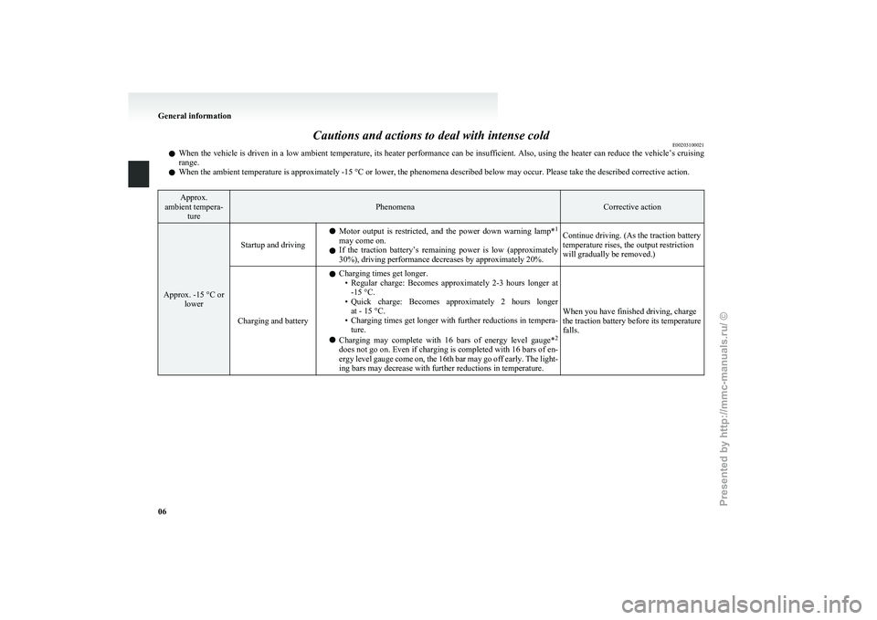
Cautions and actions to deal with intense cold
E00203100021
l When
the vehicle is driven in a low ambient temperature, its heater performance can be insufficient. Also, using the heater can reduce the vehicle’s cruising
range.
l When the ambient temperature is approximately -15 °C or lower, the phenomena described below may occur. Please take the described corrective action. Approx.
ambient tempera- ture Phenomena Corrective action
Approx. -15 °C or
lower Startup and driving
l
Motor
output is restricted, and the power down warning lamp* 1
may come on.
l If the traction battery’s remaining power is low (approximately
30%), driving performance decreases by approximately 20%. Continue driving. (As the traction battery
temperature rises, the output restriction
will gradually be removed.)
Charging and battery l
Charging times get longer.
• Regular
charge: Becomes approximately 2-3 hours longer at
-15 °C.
• Quick charge: Becomes approximately 2 hours longer at - 15 °C.
• Charging times get longer with further reductions in tempera- ture.
l Charging may complete with 16 bars of energy level gauge* 2
does not go on. Even if charging is completed with 16 bars of en-
ergy level gauge come on, the 16th bar may go off early. The light-
ing bars may decrease with further reductions in temperature. When you have finished driving, charge
the traction battery before its temperature
falls.General information
06
Presented by http://mmc-manuals.ru/ \251
Page 24 of 193
WARNING
• Make sure to use the EV charging ca- ble that comes with the vehicle.
• Do not charge another vehicle using the attached EV charging cable.
Doing so the cable may be heated and
this might result in fire.
• Make sure to use an outlet that is pro- tected from water entering.
• Do not perform charging with the body cover.
• Do not remove and insert plugs with wet hands.
• Do not charge the battery if there is a risk of lightning.
l If abnormal smells are detected or the ve-
hicle produces smoke, quickly stop charg-
ing.
l Do not perform charging at a poorly ven-
tilated place with surroundings covered.
Keep sparks, cigarettes, and flames away
from the auxiliary battery.
Flammable gas generated from the auxili-
ary battery in charging may be filled in a
building, resulting in explosion.
If charging is inevitably required, venti-
late the area well.
l Grasp the regular charging plug when
connecting or disconnecting the EV charg-
ing cable.
Grasping the cable could cause an elec-
tric shock, short circuit, and/or fire. CAUTION
l
Do not perform charging from other pow-
er source like a generator. Doing so could
cause a malfunction.
l During charging, the cooling fans inside
the bonnet room may automatically be op-
erated even if the electric motor switch is
in the “LOCK” position.
Keep your hands away from the cooling
fan during charging.
NOTE l The
on board charger is only for rated AC
220-240 V outlets.
l When connecting or disconnecting the regu-
lar charging plug, insert/pull out the plug
straight.
Also, do not incline or twist the plug.
Doing so could cause a bad connection or mal-
function.
l Make sure to lock the doors to prevent theft,
etc. during charging.
Charging from rated AC 220-240 V
outlet E08301000023
1. Fully
apply the parking brake and place the
selector lever to the “P” (PARK) position.
2. Stop the electric devices such as lamps and turn the electric motor switch to the “LOCK”
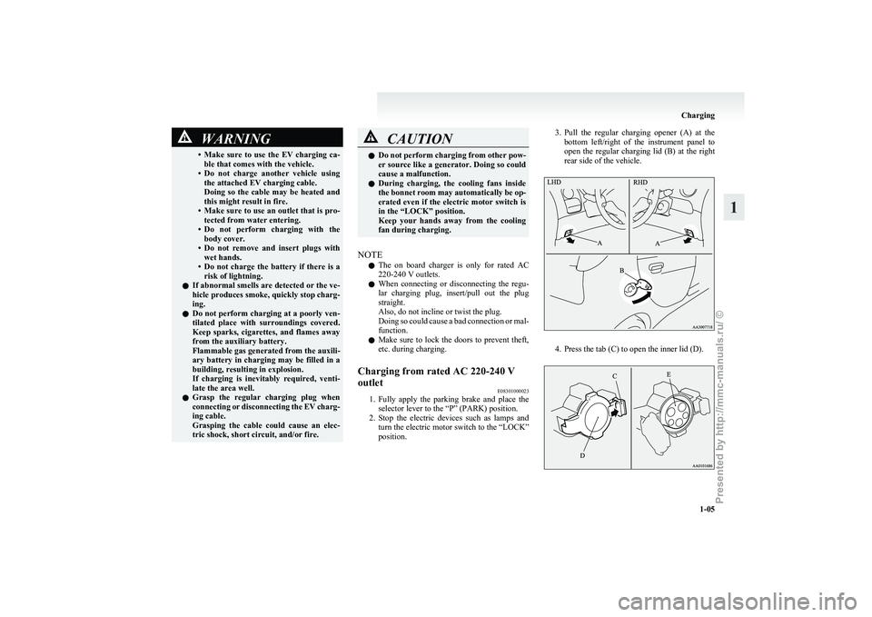
position. 3. Pull
the regular charging opener (A) at the
bottom left/right of the instrument panel to
open the regular charging lid (B) at the right
rear side of the vehicle. 4. Press the tab (C) to open the inner lid (D). Charging
1-05 1
Presented by http://mmc-manuals.ru/ \251
Page 31 of 193
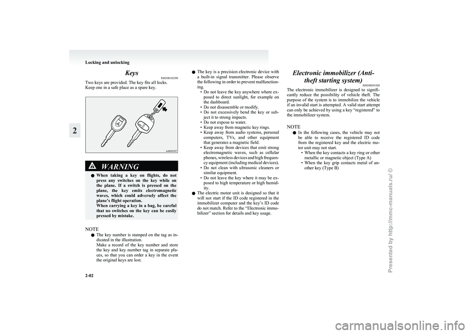
Keys
E00300102399
Two keys are provided. The key fits all locks.
Keep one in a safe place as a spare key. WARNING
l When taking a key on flights, do not
press any switches on the key while on
the plane. If a switch is pressed on the
plane, the key emits electromagnetic
waves, which could adversely affect the
plane’s flight operation.
When carrying a key in a bag, be careful
that no switches on the key can be easily
pressed by mistake.
NOTE l The
key number is stamped on the tag as in-
dicated in the illustration.
Make a record of the key number and store
the key and key number tag in separate pla-
ces, so that you can order a key in the event
the original keys are lost. l
The
key is a precision electronic device with
a built-in signal transmitter. Please observe
the following in order to prevent malfunction-
ing. • Do not leave the key anywhere where ex-posed to direct sunlight, for example on
the dashboard.
• Do not disassemble or modify.
• Do not excessively bend the key or sub- ject it to strong impacts.
• Do not expose to water.
• Keep away from magnetic key rings.
• Keep away from audio systems, personal computers, TVs, and other equipment
that generates a magnetic field.
• Keep away from devices that emit strong electromagnetic waves, such as cellular
phones, wireless devices and high frequen-
cy equipment (including medical devices).
• Do not clean with ultrasonic cleaners or similar equipment.
• Do not leave the key where it may be ex- posed to high temperature or high humid-
ity.
l The electric motor unit is designed so that it
will not start if the ID code registered in the
immobilizer computer and the key’s ID code
do not match. Refer to the “Electronic immo-
bilizer” section for details and key usage. Electronic immobilizer (Anti-
theft starting system) E00300201928
The
electronic immobilizer is designed to signifi-
cantly reduce the possibility of vehicle theft. The
purpose of the system is to immobilize the vehicle
if an invalid start is attempted. A valid start attempt
can only be achieved by using a key “registered” to
the immobilizer system.
NOTE
l In the following cases, the vehicle may not
be able to receive the registered ID code
from the registered key and the electric mo-
tor unit may not start.
• When the key contacts a key ring or othermetallic or magnetic object (Type A)
• When the key grip contacts metal of an- other key (Type B) Locking and unlocking
2-02
2
Presented by http://mmc-manuals.ru/ \251
Page 43 of 193
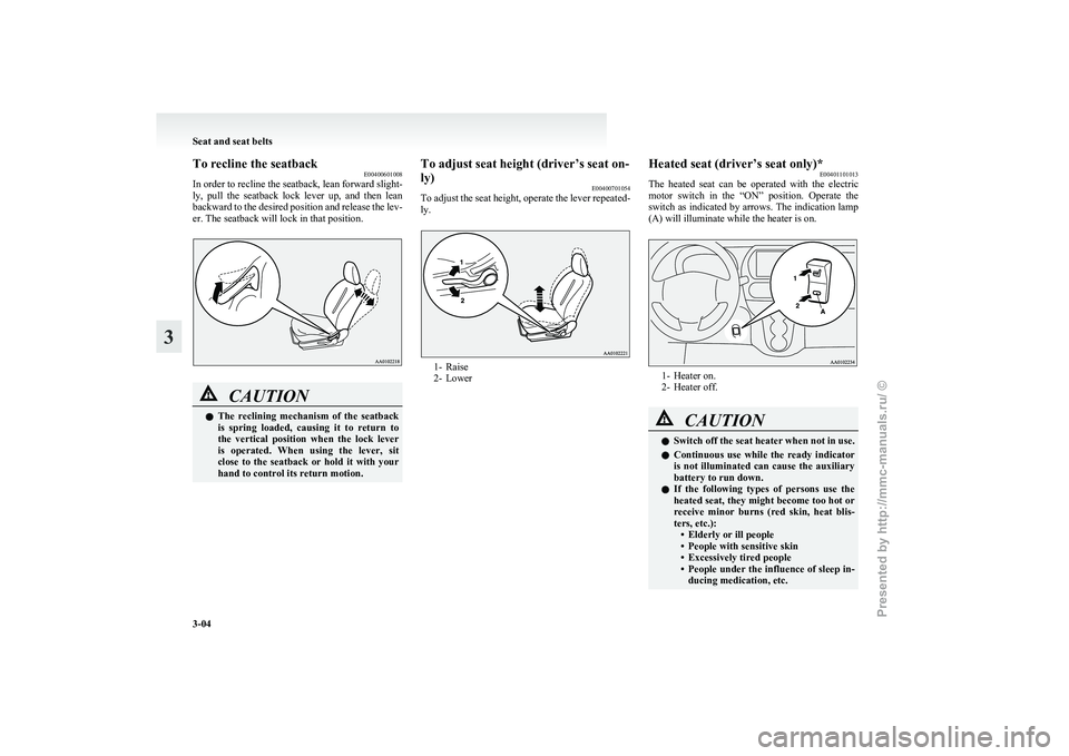
To recline the seatback
E00400601008
In
order to recline the seatback, lean forward slight-
ly, pull the seatback lock lever up, and then lean
backward to the desired position and release the lev-
er. The seatback will lock in that position. CAUTION
l
The
reclining mechanism of the seatback
is spring loaded, causing it to return to
the vertical position when the lock lever
is operated. When using the lever, sit
close to the seatback or hold it with your
hand to control its return motion. To adjust seat height (driver’s seat on-
ly)
E00400701054
To
adjust the seat height, operate the lever repeated-
ly. 1- Raise
2-
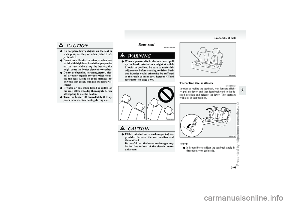
Lower Heated seat (driver’s seat only)*
E00401101013
The
heated seat can be operated with the electric
motor switch in the “ON” position. Operate the
switch as indicated by arrows. The indication lamp
(A) will illuminate while the heater is on. 1- Heater on.
2-
Heater off. CAUTION
l
Switch
off the seat heater when not in use.
l Continuous use while the ready indicator
is not illuminated can cause the auxiliary
battery to run down.
l If the following types of persons use the
heated seat, they might become too hot or
receive minor burns (red skin, heat blis-
ters, etc.):
• Elderly or ill people
• People with sensitive skin
• Excessively tired people
• People under the influence of sleep in-ducing medication, etc. Seat and seat belts
3-04
3
Presented by http://mmc-manuals.ru/ \251
Page 44 of 193
CAUTION
l
Do not place heavy objects on the seat or
stick pins, needles, or other pointed ob-
jects into it.
l Do not use a blanket, cushion, or other ma-
terial with high heat insulation properties
on the seat while using the heater; this
might cause the heater element to overheat
l Do not use benzine, kerosene, petrol, alco-
hol or other organic solvents when clean-
ing the seat. Doing so could damage not
only the seat cover, but also the heater el-
ement.
l If water or any other liquid is spilled on
the seat, allow it to dry thoroughly before
attempting to use the heater.
l Turn the heater off immediately if it ap-
pears to be malfunctioning during use. Rear seat
E00401300353 WARNING
l When
a person sits in the rear seat, pull
up the head restraint to a height at which
it locks in position. Be sure to make this
adjustment before starting to drive. Seri-
ous injuries could otherwise be suffered
as the result of an impact. Refer to “Head
restraints” on page 3-07. CAUTION
l
Child
restraint lower anchorages (A) are
provided between the seat cushion and
the seatback.
Be careful that the lower anchorages may
be hot due to heat of the electric motor
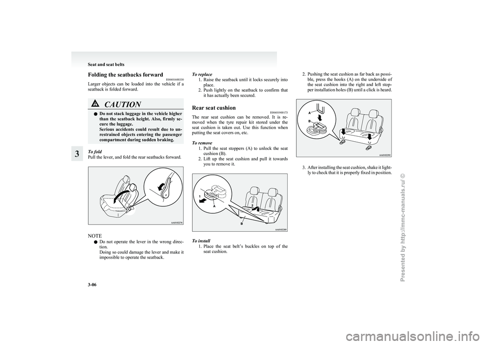
unit room. To recline the seatback
E00401500254
In order to recline the seatback, lean forward slight-
ly,
pull the lever, and then lean backward to the de-
sired position and release the lever. The seatback
will lock in that position. NOTE
l It
is possible to adjust the seatback angle in-
dependently on each side. Seat and seat belts
3-05 3
Presented by http://mmc-manuals.ru/ \251
Page 45 of 193
Folding the seatbacks forward
E00401600330
Larger
objects can be loaded into the vehicle if a
seatback is folded forward. CAUTION
l
Do
not stack luggage in the vehicle higher
than the seatback height. Also, firmly se-
cure the luggage.
Serious accidents could result due to un-
restrained objects entering the passenger
compartment during sudden braking.
To fold
Pull the lever, and fold the rear seatbacks forward. NOTE
l Do
not operate the lever in the wrong direc-
tion.
Doing so could damage the lever and make it
impossible to operate the seatback. To replace
1. Raise
the seatback until it locks securely into
place.
2. Push lightly on the seatback to confirm that it has actually been secured.
Rear seat cushion E00401900173
The rear seat cushion can be removed. It is re-
moved
when the tyre repair kit stored under the
seat cushion is taken out. Use this function when
putting the seat covers on, etc.
To remove
1. Pull the seat stoppers (A) to unlock the seatcushion (B).
2. Lift up the seat cushion and pull it towards you to remove it. To install
1. Place
the seat belt’s buckles on top of the
seat cushion. 2. Pushing the seat cushion as far back as possi-
ble,
press the hooks (A) on the underside of
the seat cushion into the right and left stop-
per installation holes (B) until a click is heard. 3. After
installing the seat cushion, shake it light-
ly to check that it is properly fixed in position. Seat and seat belts
3-06
3
Presented by http://mmc-manuals.ru/ \251
Page 48 of 193
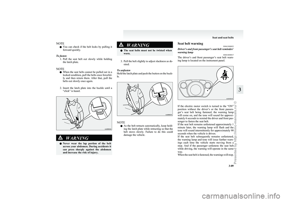
NOTE
l You
can check if the belt locks by pulling it
forward quickly.
To fasten 1. Pull the seat belt out slowly while holdingthe latch plate.
NOTE l When the seat belts cannot be pulled out in a
locked condition, pull the belts once forceful-
ly and then return them. After that, pull the
belts out slowly once again.
2. Insert the latch plate into the buckle until a “click” is heard. WARNING
l Never
wear the lap portion of the belt
across your abdomen. During accidents it
can press sharply against the abdomen
and increase the risk of injury. WARNING
l The
seat belts must not be twisted when
worn.
3. Pull
the belt slightly to adjust slackness as de- sired.
To unfasten
Hold the latch plate and push the button on the buck-
le. NOTE
l As
the belt retracts automatically, keep hold-
ing the latch plate while retracting so that the
belt stows slowly. Failure to do this could
damage the vehicle. Seat belt warning
E00413000025
Driver’s and front passenger’s seat belt reminder/
warning lamp E00414800017
The driver’s and front passenger’s seat belt warn-
ing lamp is located on the instrument panel. If the electric motor switch is turned to the “ON”
position
without the driver’s or the front passen-
ger’s seat belt being fastened, the warning lamp
will come on, and the tone will sound for approxi-
mately 6 seconds to remind the driver and front pas-
senger to fasten the seat belt.
If the seat belt remains unfastened approximately 1
minute later, the warning lamp will flash and the
tone will sound intermittently for approximately 90
seconds when the vehicle is driven.
If the seat belt subsequently remains unfastened,
the warning lamp and tone will issue further warn-
ings each time the vehicle starts moving from a
stop. And if the passenger unfastens the seat belt
while driving, the warning will operate in the same
way.
When the seat belt is fastened, the warnings will stop. Seat and seat belts
3-09 3
Presented by http://mmc-manuals.ru/ \251
Page 60 of 193
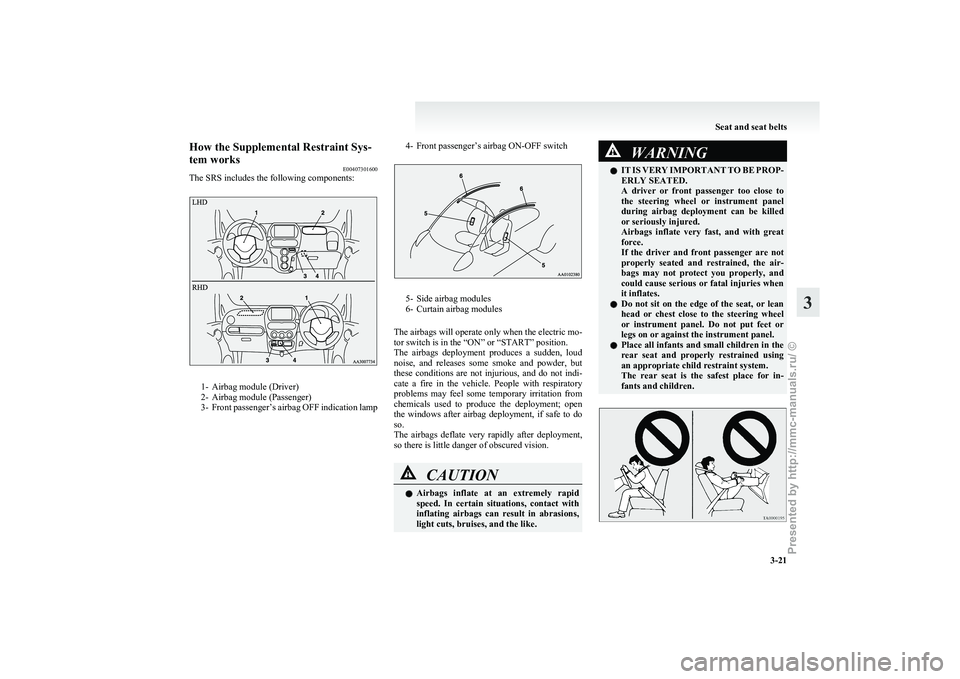
How the Supplemental Restraint Sys-
tem works
E00407301600
The SRS includes the following components: 1- Airbag module (Driver)
2-
Airbag module (Passenger)
3- Front passenger’s airbag OFF indication lamp 4- Front passenger’s airbag ON-OFF switch 5- Side airbag modules
6-
Curtain airbag modules
The airbags will operate only when the electric mo-
tor switch is in the “ON” or “START” position.
The airbags deployment produces a sudden, loud
noise, and releases some smoke and powder, but
these conditions are not injurious, and do not indi-
cate a fire in the vehicle. People with respiratory
problems may feel some temporary irritation from
chemicals used to produce the deployment; open
the windows after airbag deployment, if safe to do
so.
The airbags deflate very rapidly after deployment,
so there is little danger of obscured vision. CAUTION
l
Airbags
inflate at an extremely rapid
speed. In certain situations, contact with
inflating airbags can result in abrasions,
light cuts, bruises, and the like. WARNING
l IT
IS VERY IMPORTANT TO BE PROP-
ERLY SEATED.
A driver or front passenger too close to
the steering wheel or instrument panel
during airbag deployment can be killed
or seriously injured.
Airbags inflate very fast, and with great
force.
If the driver and front passenger are not
properly seated and restrained, the air-
bags may not protect you properly, and
could cause serious or fatal injuries when
it inflates.
l Do not sit on the edge of the seat, or lean
head or chest close to the steering wheel
or instrument panel. Do not put feet or
legs on or against the instrument panel.
l Place all infants and small children in the
rear seat and properly restrained using
an appropriate child restraint system.
The rear seat is the safest place for in-
fants and children. Seat and seat belts
3-21 3
Presented by http://mmc-manuals.ru/ \251
Page 72 of 193
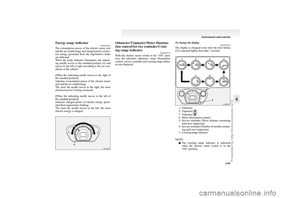
Energy usage indicator
E00529600014
The
consumption power of the electric motor unit
and the air conditioning, and charged power of elec-
tric energy generated from the regenerative brake
are indicated.
When the ready indicator illuminates, the indicat-
ing needle moves to the standard position (A) and
moves to the left or right according to the use con-
ditions of the vehicle.
[When the indicating needle moves to the right of
the standard position]
Indicates consumption power of the electric motor
unit and the air conditioning.
The more the needle moves to the right, the more
electrical power is being consumed.
[When the indicating needle moves to the left of
the standard position]
Indicates charged power of electric energy gener-
ated from regenerative braking.
The more the needle moves to the left, the more
electric energy is charged. Odometer/Tripmeter/Meter illumina-
tion control/Service reminder/Cruis-
ing range indicator
E00500601214
With
the electric motor switch in the “ON” posi-
tion, the odometer, tripmeter, meter illumination
control, service reminder and cruising range indica-
tor are displayed. To change the display
E00530700015
The
display is changed every time the reset button
(A) is pressed lightly (less than 1 second). 1- Odometer
2-
Tripmeter 3-
Tripmeter 4- Meter illumination control
5- Service
reminder (Drive distance remaining
until next inspection)
6- Service reminder (Number of months remain- ing until next inspection)
7- Cruising range indicator
NOTE l The cruising range indicator is indicated
when the electric motor switch is in the
“ON” position. Instruments and controls
4-03 4
Presented by http://mmc-manuals.ru/ \251