MITSUBISHI iMiEV 2016 1.G Owners Manual
Manufacturer: MITSUBISHI, Model Year: 2016, Model line: iMiEV, Model: MITSUBISHI iMiEV 2016 1.GPages: 296, PDF Size: 7.79 MB
Page 231 of 296
General information about your radio
Comfort controls 7-29
7
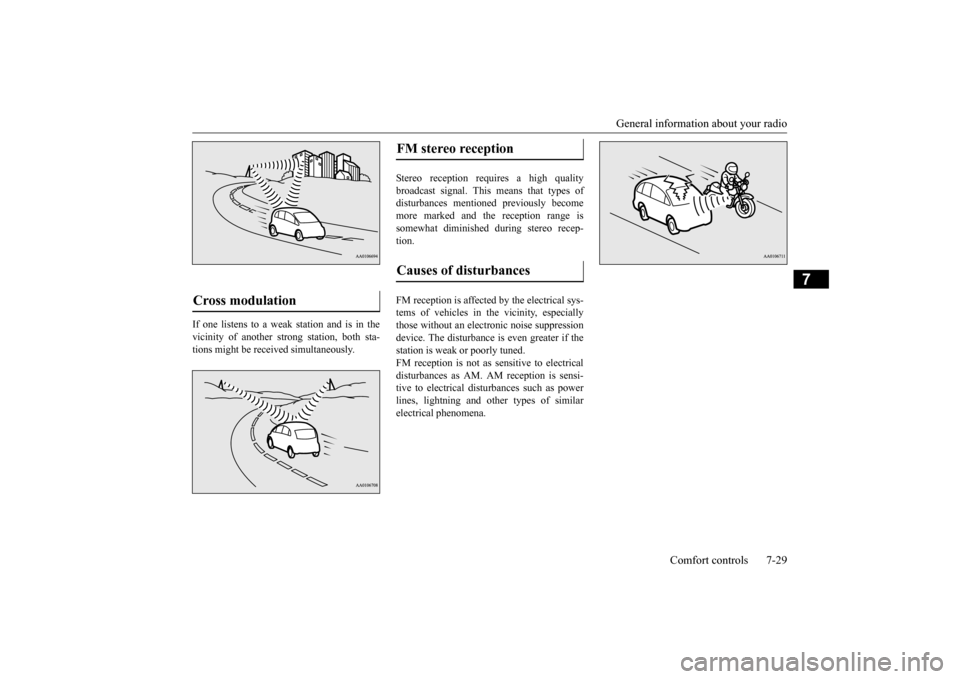
If one listens to a weak station and is in the vicinity of another st
rong station, both sta-
tions might be received simultaneously.
Stereo reception requires a high quality broadcast signal. This means that types of disturbances mentioned previously becomemore marked and the reception range is somewhat diminished during stereo recep- tion. FM reception is affected by the electrical sys- tems of vehicles in the vicinity, especially those without an electr
onic noise suppression
device. The disturbance is even greater if thestation is weak or poorly tuned. FM reception is not as sensitive to electrical disturbances as AM. AM
reception is sensi-
tive to electrical dist
urbances such as power
lines, lightning and ot
her types of similar
electrical phenomena.
Cross modulation
FM stereo reception Causes of disturbances
BK0220401US.book 29 ページ 2015年6月3日 水曜日 午前7時42分
Page 232 of 296

BK0220401US.book 30 ページ 2015年6月3日 水曜日 午前7時42分
Page 233 of 296
8
For emergenciesIf the vehicle breaks down ...............................................................8-2 Jump-starting ...................................................................................8-2 Tire repair kit ...................................................................................8-5Towing ........................................................................................... 8-11 Operation under adverse driving conditions
...........
.........
.........
.....8-13
BK0220401US.book 1 ページ 2015年6月3日 水曜日 午前7時42分
Page 234 of 296
If the vehicle breaks down 8-2 For emergencies
8
N00836301243
If your vehicle breaks down on the road, move to the shoulder and turn on the hazard warning flashers. If there is no shoulder, orthe shoulder is not safe, drive in the right lane slowly, with the hazard lights flashing, until you come to a safe stopping place. Keep theflashers flashing. If the ready indicator light goes out while driving, the brakes a
nd steering will continue
to work, but without power assist, so more effort will be required
for braking and steer-
ing. Stop the vehicle on the shoulder of the road and turn on the hazard warning flashers. If you need to push your vehicle, turn theelectric motor switch to the “ON” position, and place the selector lever in the “N” (NEU- TRAL) position.
N00836400742
If the electric motor unit cannot be energizedbecause the 12V starter battery is weak ordead, you can start it with the battery from another vehicle using jumper cables.
1. Take off any metal jewelry such as watch bands or bracelets
that might make an
accidental electrical contact. 2. Position the vehi
cles close enough
together so that the jumper cables can reach, but be sure the vehicles are nottouching each other.
3. Set the parking brake firmly on your vehi- cle and move the selector lever into the “P” (PARK) position. 4. Set the parking brake firmly on the othervehicle. Put the automatic transaxle in “P”5. Turn the ignition switch (the electric motor switch) on each vehicle to the “LOCK” position. 6. Remove the battery
cover, and then make
sure your 12V starter
battery electrolyte is
at the proper level. (Refer to “Checking 12V starter battery electrolyte level” onpage 9-8.)
If the vehicle breaks down Jump-starting
WA R N I N G To reduce the risk of igniting flammable gas that may be em
itted from the 12V
starter battery, carefully read this sectionbefore jump-starting the vehicle. Do not try to start the electric motor unit by pushing or towing the vehicle. This can cause an accident re
sulting in serious
injury or death and
can damage the vehi-
cle.CAUTION Do not attempt jump st
arting the 12V starter
battery while the main
drive lithium-ion bat-
tery is being charged. Doing so could dam-age the vehicle or charging equipment.NOTE
Do not use jumper cables if they have dam- age or corrosion.
CAUTION Check the other vehicle.
It must have a 12V
battery. If the other system is not 12V, bothsystems can be damaged.NOTE
Turn off all lights, heat
er, and othe
r electrical
loads. This will
help avoid sparks.
BK0220401US.book 2 ページ 2015年6月3日 水曜日 午前7時42分
Page 235 of 296
Jump-starting
For emergencies 8-3
8
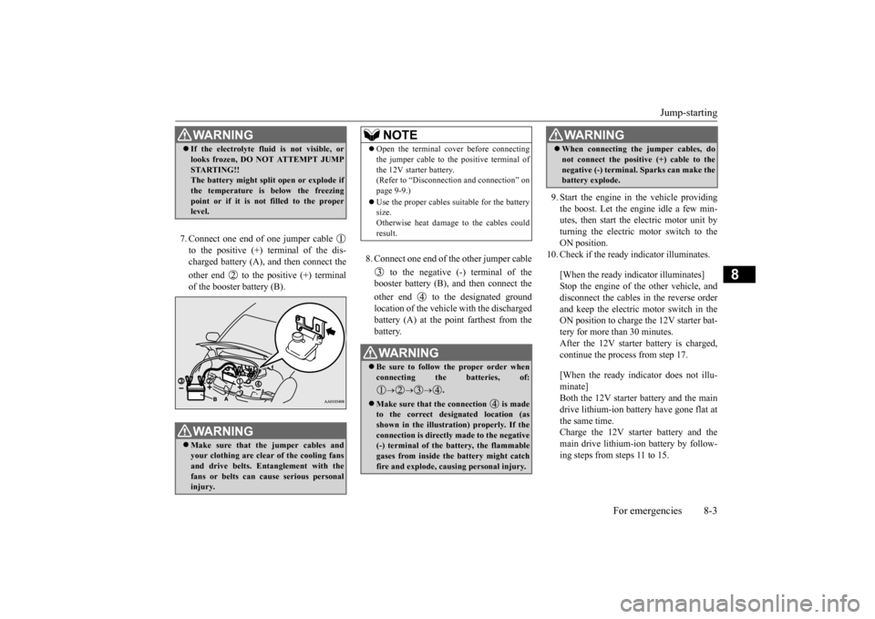
7. Connect one end of one jumper cable to the positive (+) terminal of the dis- charged battery (A),
and then connect the
other end to the positive (+) terminal of the booster battery (B).
8. Connect one end of the other jumper cable
to the negative (-) terminal of the booster battery (B), and then connect the other end to the designated ground location of the vehicle with the discharged battery (A) at the point farthest from the battery.
9. Start the engine in the vehicle providing the boost. Let the engine idle a few min- utes, then start the electric motor unit byturning the electric motor switch to the ON position.
10. Check if the ready
indicator illuminates.
[When the ready indicator illuminates] Stop the engine of the other vehicle, and disconnect the cables in the reverse order and keep the electric motor switch in theON position to charge the 12V starter bat- tery for more than 30 minutes. After the 12V starter battery is charged,continue the process from step 17. [When the ready indicator does not illu- minate] Both the 12V starter battery and the maindrive lithium-ion battery
have gone flat at
the same time. Charge the 12V starter battery and themain drive lithium-i
on battery by follow-
ing steps from steps 11 to 15.
WA R N I N G If the electrolyte flui
d is not visible, or
looks frozen, DO NOT ATTEMPT JUMPSTARTING!! The battery might split open or explode if the temperature is below the freezing point or if it is not filled to the properlevel. WA R N I N G Make sure that the jumper cables and your clothing are clear of the cooling fansand drive belts. Entanglement with the fans or belts can cause serious personal injury.
NOTE
Open the terminal cover before connecting the jumper cable to the positive terminal ofthe 12V starter battery. (Refer to “Disconnect
ion and connection” on
page 9-9.) Use the proper cables suitable for the battery size. Otherwise heat damage
to the cables could
result.WA R N I N G Be sure to follow the proper order when connecting the batteries, of:
.
Make sure that the connection is made to the correct designated location (as shown in the illustration) properly. If theconnection is directly made to the negative (-) terminal of the battery, the flammable gases from inside the battery might catchfire and explode, caus
ing personal injury.
When connecting the jumper cables, do not connect the positive (+) cable to thenegative (-) terminal. Sparks can make thebattery explode.WA R N I N G
BK0220401US.book 3 ページ 2015年6月3日 水曜日 午前7時42分
Page 236 of 296
Jump-starting 8-4 For emergencies
8
11. Keep the jumper cables to each vehicle
connected and turn
the electric motor
switch of your vehicle to the “LOCK”
12. Charge the main drive lithium-ion battery
by regular charging. The 12V starter bat-tery will automatically charge while the main drive lithium-ion battery is charging. (Refer to “Regular charging” on page3-16.)
13. When the charging indicator on the instru-
ment cluster is ill
uminated, stop the
engine of the other
vehicle and disconnect
the jumper cables in the reverse order.
14. Charge the main dr
ive lithium-ion battery
for more than 1 hour.
15. Disconnect the charging cable.
(Refer to “Regular charging” on page 3-16.)
16. Turn the electric motor switch to the
“START” position, make sure that the ready indicator on the instrument cluster is illuminated.If the ready indicator
does not illuminate,
perform the procedure again starting from step 5. If charging
cannot be performed,
consult a certified i-MiEV dealer.
17. Refit the battery cover. (“Checking 12V
starter battery electr
olyte level” on page
9-8.)
NOTE
The jumper cables need to be connected to the 12V starter battery when you start charg-ing the main drive lithium-ion battery because the on board char
ger etc. operate uti-
lizing power from the
12V starter battery.
NOTE
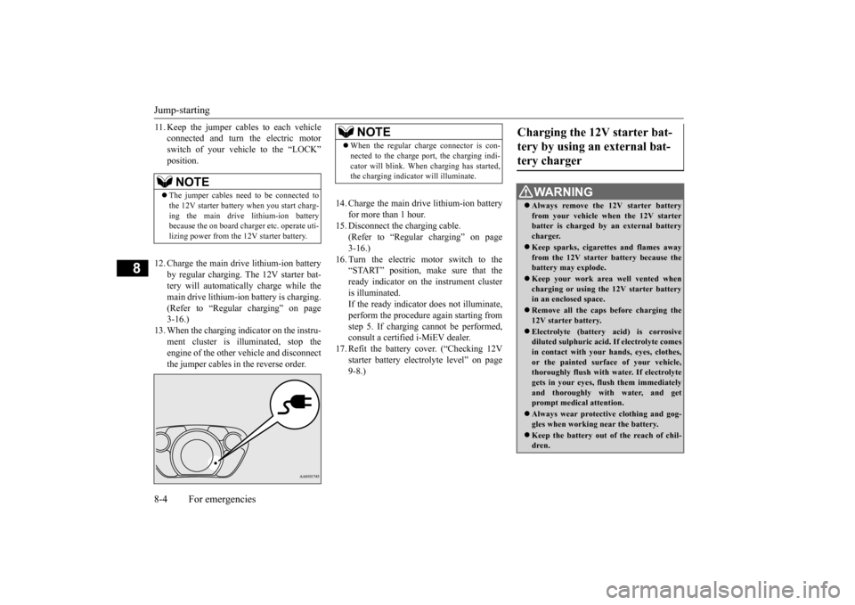
When the regular charge connector is con- nected to the charge port, the charging indi-cator will blink. When charging has started,the charging indicator will illuminate.
Charging the 12V starter bat- tery by using an external bat-tery charger
WA R N I N G Always remove the
12V starter battery
from your vehicle wh
en the 12V starter
batter is charged by an external battery charger. Keep sparks, cigare
ttes and flames away
from the 12V starter battery because thebattery may explode. Keep your work area well vented when charging or using the 12V starter battery in an enclosed space. Remove all the caps before charging the 12V starter battery. Electrolyte (battery acid) is corrosive diluted sulphuric acid.
If electrolyte comes
in contact with your hands, eyes, clothes,or the painted surf
ace of your vehicle,
thoroughly flush with water. If electrolyte gets in your eyes, flush them immediatelyand thoroughly with
water, and get
prompt medical attention. Always wear protective clothing and gog- gles when working near the battery. Keep the battery out of the reach of chil- dren.
BK0220401US.book 4 ページ 2015年6月3日 水曜日 午前7時42分
Page 237 of 296
Tire repair kit
For emergencies 8-5
8
If you drive your vehicle with a low battery charge, after the electric motor unit has beenstarted by using jumper
cables, it can cause
the anti-lock braking sy
stem warning light to
illuminate. This is only due to the low batteryvoltage. It is not a problem with the brake system. If this happens, fully charge the 12V starter battery and ensure the charging system is operating properly.
N00836600366
This vehicle is equipped
with a tire repair kit
which can be used to repair a minor puncture in tread area caused by
a nail, screw or simi-
lar object. A spare tire
is not provided with
this vehicle.
N00837701026
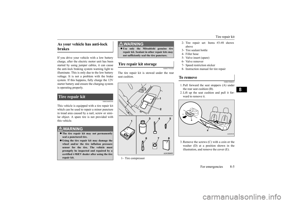
The tire repair kit is
stowed under the rear
seat cushion.
N00837800033
1. Pull forward the seat stoppers (A) underthe rear seat cushion (B). 2. Lift up the seat
cushion and pull it for-
ward to remove it. 3. Remove the screws (C) with a coin or the washer (D) at a position shown in the illustration, and re
move the cover (E).
As your vehicle has anti-lock brakes Tire repair kit
WA R N I N G The tire repair kit may not permanently seal a punctured tire. Using the tire repair
kit may damage the
wheel and/or the tire inflation pressuresensor for the tire. The vehicle must promptly be inspected and repaired by a certified i-MiEV dealer after using the tirerepair kit.
Use only the Mitsubishi genuine tire repair kit. Sealant in other repair kits maynot sufficiently seal the tire puncture.
Tire repair kit storage 1- Tire compressorWA R N I N G
2- Tire repair set: Items #3-#8 shown
above
3- Tire sealant bottle4- Filler hose 5- Valve insert (spare)7- Speed restriction sticker 8- Instruction manual for tire repairTo remove
BK0220401US.book 5 ページ 2015年6月3日 水曜日 午前7時42分
Page 238 of 296
Tire repair kit 8-6 For emergencies
8
4. Remove the tire repair kit.
N00837900018
1. Return the tire repair kit to its original place. Attach the cover and fasten the screws.2. Insert two wire tabs at
the rear edge of the
seat cushion under the seat back.
3. Pass both rear seat
belt buckles through
slits at the rear edge of the seat cushion.Make sure that the seat belt buckles are not twisted. 4. While pushing the seat cushion as farback as possible, press down hooks (A) under the seat cushion into the right and left stopper installa
tion holes (B) until a
click is heard. 5. After installing the seat cushion, shake it lightly to confirm that it is properly fixedin position.
N00800201049
To store
How to use the tire repair kit
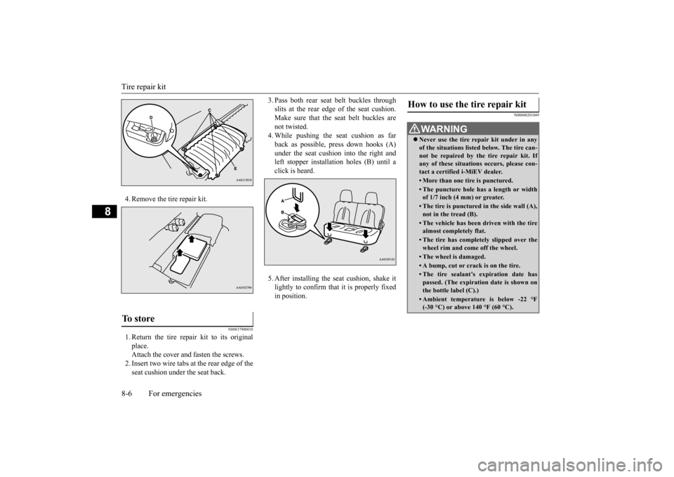
WA R N I N G Never use the tire repair kit under in any of the situations listed below. The tire can-not be repaired by the tire repair kit. If any of these situations occurs, please con- tact a certified i-MiEV dealer.• More than one tire is punctured.• The puncture hole has a length or width of 1/7 inch (4 mm) or greater.• The tire is punctured in the side wall (A),not in the tread (B).• The vehicle has been driven with the tirealmost completely flat.• The tire has completely slipped over thewheel rim and come off the wheel.• The wheel is damaged.• A bump, cut or crack is on the tire.• The tire sealant’s expiration date has passed. (The expiration date is shown onthe bottle label (C).)(-30 °C) or above 140 °F (60 °C).
BK0220401US.book 6 ページ 2015年6月3日 水曜日 午前7時42分
Page 239 of 296
Tire repair kit
For emergencies 8-7
8
1. Park the vehicle on a
safe, flat and level
place. 2. Set the parking brake firmly. 3. Move the selector
lever to the “P”
motor switch to the “LOCK” position. 4. Turn on the hazard warning flashers andset up a warning sign, such as a warning triangle or flashing signal lamp, at an ade- quate distance from the vehicle, and haveall your passengers leave the vehicle. 5. Take out the tire repair kit.
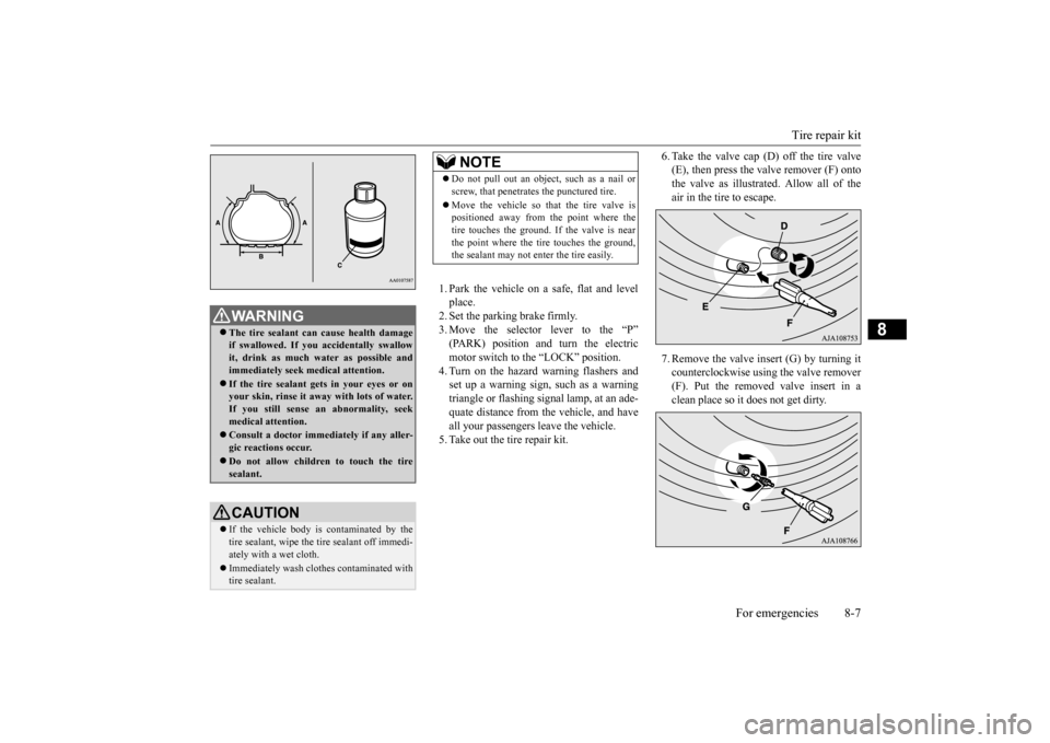
6. Take the valve cap (D) off the tire valve (E), then press the valve remover (F) ontothe valve as illustrated. Allow all of the air in the tire to escape. 7. Remove the valve insert (G) by turning it counterclockwise using the valve remover(F). Put the removed valve insert in a clean place so it does not get dirty.
WA R N I N G The tire sealant can
cause health damage
if swallowed. If you
accidentally swallow
it, drink as much water as possible and immediately seek medical attention. If the tire sealant gets in your eyes or on your skin, rinse it away with lots of water. If you still sense an
abnormality, seek
medical attention. Consult a doctor immediately if any aller- gic reactions occur. Do not allow children to touch the tire sealant.CAUTION If the vehicle body is contaminated by the tire sealant, wipe the tire sealant off immedi- ately with a wet cloth. Immediately wash clothes contaminated with tire sealant.
NOTE
Do not pull out an object, such as a nail or screw, that penetrat
es the punctured tire.
Move the vehicle so that the tire valve is positioned away from the point where the tire touches the ground. If the valve is nearthe point where the tire touches the ground, the sealant may not enter the tire easily.
BK0220401US.book 7 ページ 2015年6月3日 水曜日 午前7時42分
Page 240 of 296
Tire repair kit 8-8 For emergencies
8
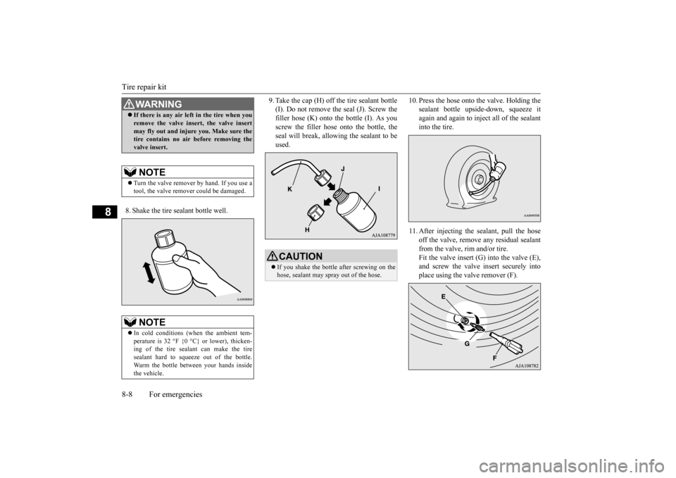
8. Shake the tire sealant bottle well.
9. Take the cap (H) off the tire sealant bottle (I). Do not remove the seal (J). Screw thefiller hose (K) onto the bottle (I). As you screw the filler hose onto the bottle, the seal will break, allowing the sealant to beused.
10. Press the hose onto the valve. Holding the
sealant bottle upside-down, squeeze itagain and again to inject all of the sealant into the tire.
11. After injecting the
sealant, pull the hose
off the valve, remove
any residual sealant
from the valve, rim and/or tire. Fit the valve insert (G) into the valve (E),and screw the valve insert securely into place using the valve remover (F).
WA R N I N G If there is any air left
in the tire when you
remove the valve inse
rt, the valve insert
may fly out and injure you. Make sure thetire contains no air before removing the valve insert.NOTE
Turn the valve remover by hand. If you use a tool, the valve remove
r could be damaged.
NOTE
In cold conditions (w
hen the ambient tem-
perature is 32