warning MITSUBISHI L200 2015 (in English) Owners Manual
[x] Cancel search | Manufacturer: MITSUBISHI, Model Year: 2015, Model line: L200, Model: MITSUBISHI L200 2015Pages: 418, PDF Size: 25.8 MB
Page 344 of 418
Service precautionsE01000100706
Adequate care of your vehicle at regular in- tervals serves to preserve the value and ap-
pearance as long as possible.
Maintenance items as described in this own- er’s manual can be performed by the owner.We recommend you to have the periodic in-
spection and maintenance performed by a MITSUBISHI MOTORS Authorized Service
Point or another specialist.
In the event a malfunction or other problem is discovered, we recommend you to have it
checked and repaired. This section contains information on inspection maintenance pro- cedures that you can do yourself. Follow the
instructions and cautions for each of the vari- ous procedures.WARNINGl When checking or servicing the inside of
the engine compartment, make sure the
engine is switched off and has had a chance to cool down.
l If it is necessary to do work in the engine
compartment with the engine running, be
especially careful that your clothing, hair, etc., does not become caught by the fans,
drive belts, or other moving parts.WARNINGl For vehicle with air conditioning, the fan
may turn on automatically even if the en-
gine is not running; turn the ignition key
to “LOCK” position and remove the key to ensure safety while you work in the en-
gine compartment.
l Do not smoke, cause sparks or allow open
flames around fuel or battery. The fumesare flammable.
l Be extremely cautious when working
around the battery. It contains poisonous
and corrosive sulphuric acid.
l Do not get under your vehicle with just
the body jack supporting it. Always use
automotive jack stands.
l Improper handling of components and
materials used in the vehicle can endanger
your personal safety. We recommend you to consult a specialist for necessary infor-
mation.Catalytic converter
E01000200925
For ordinary use, there are no particular pre-cautions.
The exhaust gas scavenging devices used
with the catalytic converter are extremely ef- ficient for the reduction of noxious gases.
The catalytic converter is installed in the ex- haust system.
It is important to keep the engine properly
tuned to ensure proper catalyst operation andprevent possible catalyst damage.CAUTIONl Damage to the catalytic converter can result
if your vehicle is not kept in proper operat-ing condition. In the event of an engine mal-
function particularly involving engine mis-
fire or other apparent loss of performance, have your vehicle serviced promptly.
Continued operation of your vehicle with a
severe overheated condition may result in possible damage to the converter and vehi-cle.WARNINGl As with any vehicle, do not park or oper-
ate this vehicle in areas where combusti-
ble materials such as dry grass or leaves
can come in contact with a hot exhaust since a fire could occur.
l Paint should not be applied to the catalyt-
ic converter.
The catalytic converter itself gets hot quickly,
and may be damaged if overheated. The fol- lowing points should be noted in order to pre-vent the ignition of unburned fuel within the
catalytic converter.
Service precautions
10-02OKTE15E3Maintenance10
Page 348 of 418
NOTElUse of additives is not recommended since
they may reduce the effectiveness of addi-
tives already included in the engine oil. It may result in failure of the mechanical as-
sembly.
Vehicles with diesel particulate
filter (DPF)
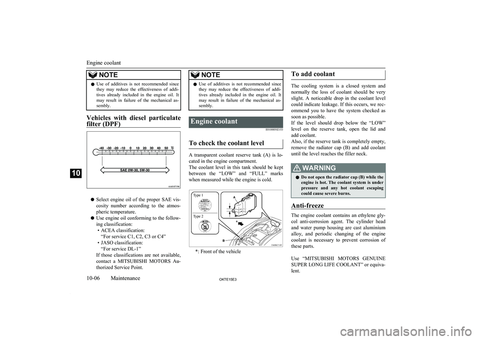
l Select engine oil of the proper SAE vis-
cosity number according to the atmos- pheric temperature.
l Use engine oil conforming to the follow-
ing classification: • ACEA classification: “For service C1, C2, C3 or C4”
• JASO classification: “For service DL-1”
If those classifications are not available, contact a MITSUBISHI MOTORS Au-
thorized Service Point.
NOTEl Use of additives is not recommended since
they may reduce the effectiveness of addi-
tives already included in the engine oil. It may result in failure of the mechanical as-
sembly.Engine coolant
E01000502153
To check the coolant level
A transparent coolant reserve tank (A) is lo-cated in the engine compartment.
The coolant level in this tank should be kept
between the “LOW” and “FULL” marks when measured while the engine is cold.
*: Front of the vehicle
To add coolant
The cooling system is a closed system and
normally the loss of coolant should be very
slight. A noticeable drop in the coolant level
could indicate leakage. If this occurs, we rec- ommend you to have the system checked as
soon as possible.
If the level should drop below the “LOW” level on the reserve tank, open the lid and
add coolant.
Also, if the reserve tank is completely empty, remove the radiator cap (B) and add coolant until the level reaches the filler neck.
WARNINGl Do not open the radiator cap (B) while the
engine is hot. The coolant system is under
pressure and any hot coolant escaping
could cause severe burns.
Anti-freeze
The engine coolant contains an ethylene gly-
col anti-corrosion agent. The cylinder head and water pump housing are cast aluminium
alloy, and periodic changing of the engine coolant is necessary to prevent corrosion of
these parts.
Use “ MITSUBISHI MOTORS GENUINE
SUPER LONG LIFE COOLANT” or equiva- lent.
Engine coolant
10-06OKTE15E3Maintenance10 Type 1
Type 2
Page 350 of 418
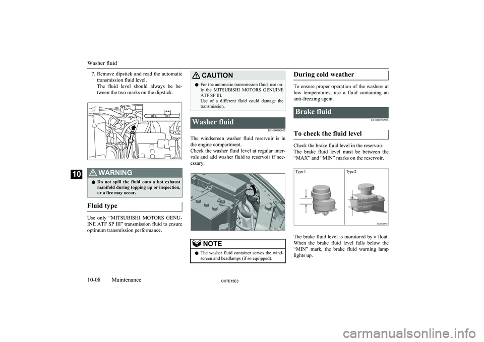
7.Remove dipstick and read the automatic
transmission fluid level.
The fluid level should always be be-
tween the two marks on the dipstick.WARNINGl Do not spill the fluid onto a hot exhaust
manifold during topping up or inspection, or a fire may occur.
Fluid type
Use only “ MITSUBISHI MOTORS GENU-
INE ATF SP III” transmission fluid to ensure
optimum transmission performance.
CAUTIONl For the automatic transmission fluid, use on-
ly the MITSUBISHI MOTORS GENUINE
ATF SP III.
Use of a different fluid could damage the transmission.Washer fluid
E01000700672
The windscreen washer fluid reservoir is inthe engine compartment.
Check the washer fluid level at regular inter- vals and add washer fluid to reservoir if nec-
essary.
NOTEl The washer fluid container serves the wind-
screen and headlamps (if so equipped).During cold weather
To ensure proper operation of the washers at
low temperatures, use a fluid containing ananti-freezing agent.
Brake fluid
E01000900935
To check the fluid level
Check the brake fluid level in the reservoir.
The brake fluid level must be between the “MAX” and “MIN” marks on the reservoir.
The brake fluid level is monitored by a float.
When the brake fluid level falls below the “MIN” mark, the brake fluid warning lamp
lights up.
Washer fluid
10-08OKTE15E3Maintenance10 Type 1 Type 2
Page 352 of 418
WARNINGlTake care in handling brake fluid as it is
harmful to the eyes and may also cause
damage to painted surfaces. Wipe up any spills immediately.Power steering fluid
E01001101407
To check the fluid level
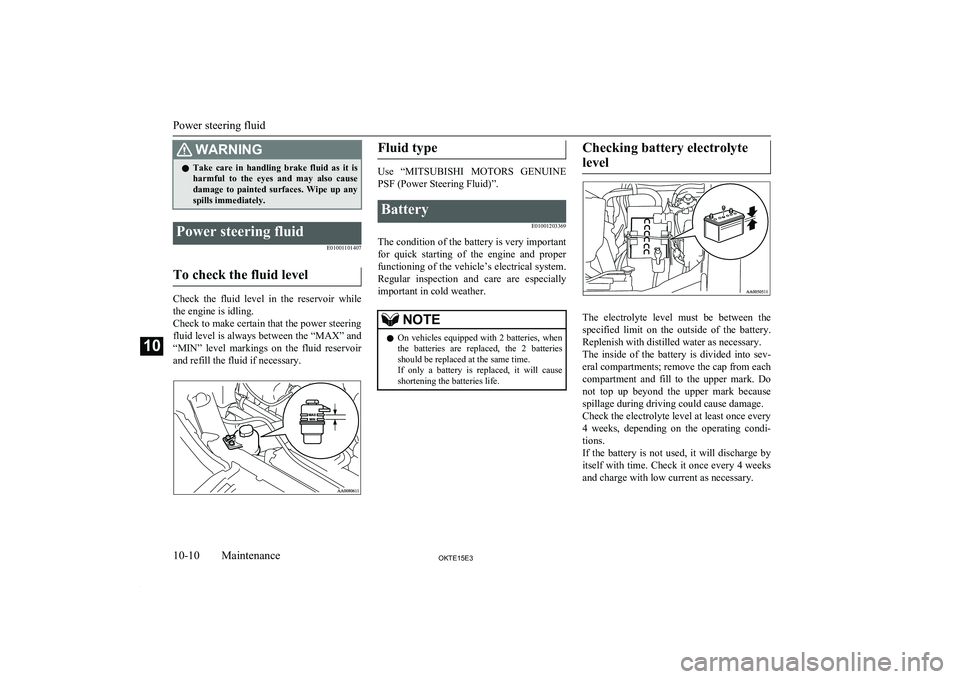
Check the fluid level in the reservoir whilethe engine is idling.
Check to make certain that the power steering
fluid level is always between the “MAX” and
“MIN” level markings on the fluid reservoir
and refill the fluid if necessary.
Fluid type
Use “ MITSUBISHI MOTORS GENUINE
PSF (Power Steering Fluid)”.
Battery
E01001203369
The condition of the battery is very important
for quick starting of the engine and proper functioning of the vehicle’s electrical system.
Regular inspection and care are especially
important in cold weather.
NOTEl On vehicles equipped with 2 batteries, when
the batteries are replaced, the 2 batteries
should be replaced at the same time.
If only a battery is replaced, it will cause shortening the batteries life.Checking battery electrolyte
level
The electrolyte level must be between the specified limit on the outside of the battery.
Replenish with distilled water as necessary.
The inside of the battery is divided into sev- eral compartments; remove the cap from each
compartment and fill to the upper mark. Do not top up beyond the upper mark because
spillage during driving could cause damage.
Check the electrolyte level at least once every
4 weeks, depending on the operating condi- tions.
If the battery is not used, it will discharge by
itself with time. Check it once every 4 weeks and charge with low current as necessary.
Power steering fluid
10-10OKTE15E3Maintenance10
Page 353 of 418

During cold weather
The capacity of the battery is reduced at lowtemperatures. This is an inevitable result of
its chemical and physical properties. This is why a very cold battery, particularly one that
is not fully charged, will only deliver a frac- tion of the starter current which is normallyavailable.
We recommend you to have the battery checked before the start of cold weather and,if necessary, have it charged or replaced.
This does not only ensure reliable starting,
but a battery which is kept fully charged also has a longer life.
Disconnection and connection
To disconnect the battery cable, stop the en- gine, first disconnect the negative (-) terminal
and then the positive (+) terminal. When con-
necting the battery, first connect the positive
(+) terminal and then the negative (-) termi- nal.
NOTEl Open the terminal cover (A) before discon-
necting or connecting the positive (+) termi-
nal of the battery.NOTEWARNINGl Keep sparks, cigarettes, and flames away
from the battery because the battery could explode.WARNINGl The battery electrolyte is extremely caus-
tic. Do not allow it to come in contact with
your eyes, skin, clothing, or the painted surfaces of the vehicle. Spilt electrolyte
should be flushed immediately with ample amounts of water.
Irritation to eyes or skin from contact
with electrolyte requires immediate medi-
cal attention.
l Ventilate when charging or using the bat-
tery in an enclosed space.CAUTIONl Never disconnect the battery with the igni-
tion switch in the “ON” position; doing so
could damage the vehicle’s electrical com- ponents.
l Never short-circuit the battery; doing so
could cause it to overheat and be damaged.
l Always wear protective eye goggles when
working near the battery.
l If the battery is to be quick-charged, first
disconnect the battery cables.
l In order to prevent a short circuit, be sure to
disconnect the negative (-) terminal first.
l Keep it out of reach of children.
Battery
10-11OKTE15E3Maintenance10 Type 1 Type 2
Page 354 of 418
CAUTIONlDo not bring the nearby parts, the plastic
parts and so on into contact with sulphuric acid (battery electrolyte) which may crack,
stain or discolour them.
If they are in contact, wipe off with soft cloth, chamois or the like and an aqueous
solution of neutral detergent then immedi-
ately rinse the affected parts with plenty of water.NOTEl Keep the terminals clean. After the battery is
connected, apply terminal protection grease.
To clean the terminals, use lukewarm water.
l Check to see if the battery is securely instal-
led and cannot be moved during travel. Also check each terminal for tightness.
l When the vehicle is to be left unused for a
long period of time, remove the battery and
store it in a place where the battery fluid will not freeze. The battery should be stored only in a fully charged condition.Tyres
E01001300239WARNINGlDriving with tyres that are worn, dam-
aged or improperly inflated can lead to a
loss of control or blow out of the tyres which can result in a collision with serious
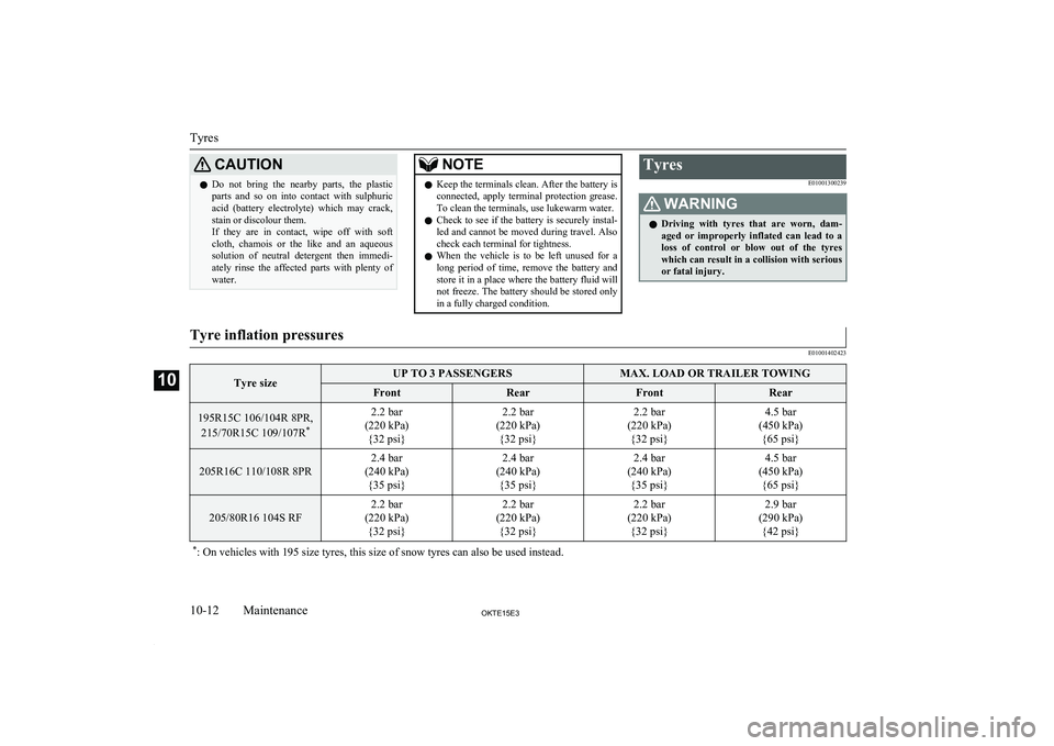
or fatal injury.Tyre inflation pressures
E01001402423Tyre sizeUP TO 3 PASSENGERSMAX. LOAD OR TRAILER TOWINGFrontRearFrontRear195R15C 106/104R 8PR,
215/70R15C 109/107R *2.2 bar
(220 kPa) {32 psi}2.2 bar
(220 kPa) {32 psi}2.2 bar
(220 kPa) {32 psi}4.5 bar
(450 kPa) {65 psi}
205R16C 110/108R 8PR
2.4 bar
(240 kPa) {35 psi}2.4 bar
(240 kPa) {35 psi}2.4 bar
(240 kPa) {35 psi}4.5 bar
(450 kPa) {65 psi}
205/80R16 104S RF
2.2 bar
(220 kPa) {32 psi}2.2 bar
(220 kPa) {32 psi}2.2 bar
(220 kPa) {32 psi}2.9 bar
(290 kPa) {42 psi}* : On vehicles with 195 size tyres, this size of snow tyres can also be used instead.
Tyres
10-12OKTE15E3Maintenance10
Page 358 of 418
The speed limit for tyre chain is 50 km/h(30 mph) and remove the tyre chains as soon as possible on snow free roads.WARNINGl DO NOT use a jack when fitting the
chains, as in thsee conditions, the tyres
may slip on the icy road causing the vehi- cle to slip off the jack.CAUTIONl Practice fitting the chains before you need
them.
Don’t expect help from other people in the
cold.
l Choose a clear straight stretch of road where
you can pull over and still be seen while you are fitting the chains.
l Do not fit chains before you need them. This
will wear out your tyres and the road sur-
face.
l After driving around 100-300 metres, stop
and retighten the chains.
l Drive carefully and do not exceed 50 km/h
(30 mph). Remember, fitting chains is notgoing to stop accidents from happening.
l When tyre chains are installed, take care that
they do not damage the disc wheel or body.
l An aluminium wheel can be damaged by a
tyre chain while driving. When fitting a tyre
chain on an aluminium wheel, take care that any part of the chain and fitting cannot be
brought into contact with the wheel.CAUTIONl When installing or removing the tyre chains,
take care that hands and other parts of your
body are not injured by the sharp edges of
the vehicle body.
l Install the chains only on the rear tyres and
tighten them as tightly as possible with the
ends securely fastened.NOTEl The laws and regulations concerning the use
of tyre chains vary. Find out and follow the laws and regulations of the area you’re driv-
ing in.
In most countries, it is prohibited by law to
use tyre chains on roads without snow.Clutch pedal free play*
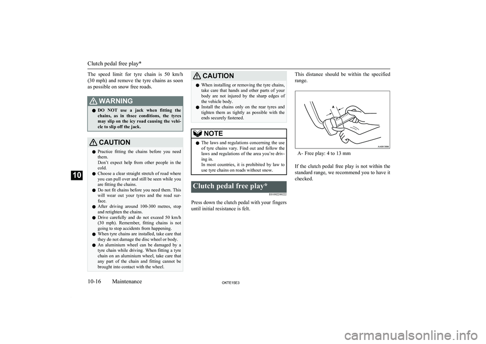
E01002200222
Press down the clutch pedal with your fingers
until initial resistance is felt.
This distance should be within the specified
range.
A- Free play: 4 to 13 mm
If the clutch pedal free play is not within the
standard range, we recommend you to have it checked.
Clutch pedal free play*
10-16OKTE15E3Maintenance10
Page 359 of 418
Brake pedal free playE01002300281
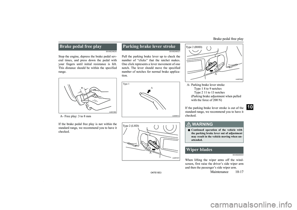
Stop the engine, depress the brake pedal sev- eral times, and press down the pedal with
your fingers until initial resistance is felt. This distance should be within the specified
range.
A- Free play: 3 to 8 mm
If the brake pedal free play is not within the standard range, we recommend you to have it
checked.
Parking brake lever stroke
E01002400527
Pull the parking brake lever up to check the number of “clicks” that the ratchet makes.
One click represents a lever movement of one
notch. The lever should move the specified number of notches for normal brake applica-
tion.
Type 1A
A- Parking brake lever stroke
Type 1 8 to 9 notches
Type 2 11 to 13 notches
(Parking brake adjustment when pulled
with the force of 200 N)
If the parking brake lever stroke is out of the
standard range, we recommend you to have it
checked.
WARNINGl Continued operation of the vehicle with
the parking brake lever out of adjustment
may result in the vehicle moving when un- attended.Wiper blades
E01002600385
When lifting the wiper arms off the wind-screen, first raise the driver’s side wiper arm
and then the passenger’s side wiper arm.
Brake pedal free play
10-17OKTE15E3Maintenance10 Type 2 (LHD)
A Type 2 (RHD)
A
Page 362 of 418
WARNINGlIf you see a suspicious fuel leak or if you
smell fuel, do not operate the vehicle; werecommend you to call for assistance.
Exterior and interior lamp op-
eration
Operate the combination lamp switch to
check that all lamps are functioning properly.
If the lamps do not illuminate, the probable cause is a blown fuse or defective lamp bulb.
Check the fuses first. If there is no blown
fuses, check the lamp bulbs.
For information regarding the inspection and
replacement of the fuses and the lamp bulbs, refer to “Fuses” on page 10-20 and “Re-
placement of lamp bulbs” on page 10-25.
If the fuses and bulbs are all OK, we recom- mend you to have your vehicle checked and
repaired.
Meter, gauge and indicator/warning lamps operation
Run the engine to check the operation of all meters, gauges, and indicator/warning lamps.
If there is anything wrong, we recommend you to have your vehicle inspected.
Hinges and latches lubrication
Check all latches and hinges, and lubricate if
necessary by first cleaning and then applying
multipurpose grease.
For cold and snowy weather
E01002800257
Ventilation slots
The ventilation slots in front of the wind-
screen should be kept clear of leaves or brushed clear after heavy snowfall, so that
the operation of the heating and ventilation
systems will not be impaired.
Weatherstripping
To prevent freezing of the weatherstripping
on the doors, bonnet, etc., they should be treated with silicone grease or spray.
Additional equipment
It is a good idea to carry a shovel or a short- handled spade in the vehicle during the win-ter so that you can clear away snow if you get
stranded. A small hand-brush for sweeping snow off the vehicle and a plastic scraper for
the windscreen and rear window are also use- ful.
Fusible links
E01002900030
The fusible links will melt to prevent a fire if
a large current attempts to flow through cer- tain electrical systems.
In case of a melted fusible link, we recom- mend you to have your vehicle inspected.Fuses
E01003000849Fuse block location
E01007600032
To prevent damage to the electrical systemdue to shortcircuiting or overloading, each in-dividual circuit is provided with a fuse.
There are fuse blocks in the passenger com- partment and in the engine compartment.
For cold and snowy weather
10-20OKTE15E3Maintenance10
Page 365 of 418
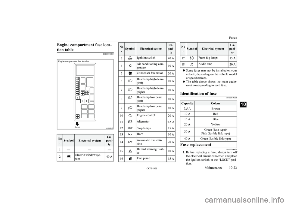
Engine compartment fuse loca-tion table
E01008000583
Engine compartment fuse locationFront
No .SymbolElectrical system
Ca-
paci- ty1———2Electric window sys-
tem40 ANo .SymbolElectrical system
Ca-
paci- ty3Ignition switch40 A4Air conditioning com-
pressor10 A5Condenser fan motor20 A6Headlamp high-beam
(left)10 A7Headlamp high-beam
(right)10 A8Headlamp low beam
(left)10 A9Headlamp low beam
(right)10 A10Engine control20 A11Alternator7.5 A12Stop lamps15 A13Horn10 A14Automatic transmis-
sion20 A15Hazard warning flash-
er10 A16Fuel pump15 ANo .SymbolElectrical system
Ca-
paci- ty17Front fog lamps15 A18Audio amp20 A
l Some fuses may not be installed on your
vehicle, depending on the vehicle model
or specifications.
l The table above shows the main equip-
ment corresponding to each fuse.
Identification of fuse
E01008100308
CapacityColour7.5 ABrown10 ARed15 ABlue20 AYellow30 AGreen (fuse type)/
Pink (fusible link type)40 AGreen (fusible link type)Fuse replacement
E01007800656
1. Before replacing a fuse, always turn off
the electrical circuit concerned and place
the ignition switch in the “LOCK” posi-
tion.
Fuses
10-23OKTE15E3Maintenance10