battery MITSUBISHI L200 2015 Owner's Manual (in English)
[x] Cancel search | Manufacturer: MITSUBISHI, Model Year: 2015, Model line: L200, Model: MITSUBISHI L200 2015Pages: 418, PDF Size: 25.8 MB
Page 34 of 418
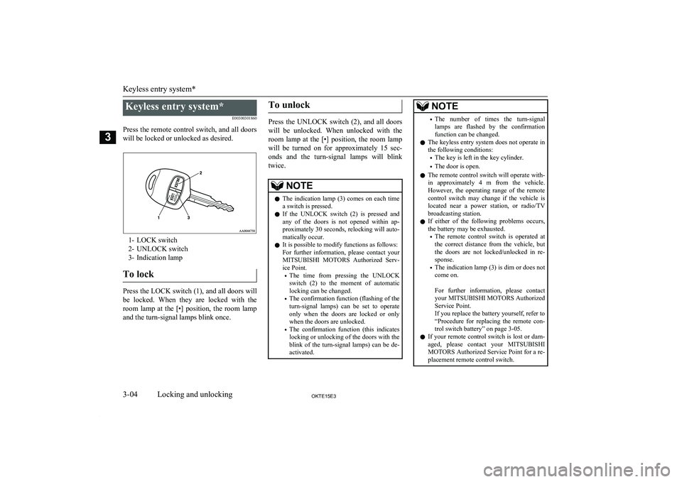
Keyless entry system*E00300301860
Press the remote control switch, and all doors will be locked or unlocked as desired.
1- LOCK switch
2- UNLOCK switch
3- Indication lamp
To lock
Press the LOCK switch (1), and all doors will
be locked. When they are locked with the room lamp at the [•] position, the room lampand the turn-signal lamps blink once.
To unlock
Press the UNLOCK switch (2), and all doors
will be unlocked. When unlocked with the
room lamp at the [•] position, the room lamp will be turned on for approximately 15 sec-
onds and the turn-signal lamps will blink twice.
NOTEl The indication lamp (3) comes on each time
a switch is pressed.
l If the UNLOCK switch (2) is pressed and
any of the doors is not opened within ap- proximately 30 seconds, relocking will auto-matically occur.
l It is possible to modify functions as follows:
For further information, please contact your MITSUBISHI MOTORS Authorized Serv-
ice Point.
• The time from pressing the UNLOCK
switch (2) to the moment of automatic locking can be changed.
• The confirmation function (flashing of the
turn-signal lamps) can be set to operate
only when the doors are locked or only when the doors are unlocked.
• The confirmation function (this indicates
locking or unlocking of the doors with the
blink of the turn-signal lamps) can be de- activated.NOTE• The number of times the turn-signal
lamps are flashed by the confirmation function can be changed.
l The keyless entry system does not operate in
the following conditions:
• The key is left in the key cylinder.
• The door is open.
l The remote control switch will operate with-
in approximately 4 m from the vehicle.
However, the operating range of the remote control switch may change if the vehicle is
located near a power station, or radio/TV broadcasting station.
l If either of the following problems occurs,
the battery may be exhausted.
• The remote control switch is operated at
the correct distance from the vehicle, but
the doors are not locked/unlocked in re- sponse.
• The indication lamp (3) is dim or does not
come on.
For further information, please contact
your MITSUBISHI MOTORS Authorized
Service Point.
If you replace the battery yourself, refer to
“Procedure for replacing the remote con- trol switch battery” on page 3-05.
l If your remote control switch is lost or dam-
aged, please contact your MITSUBISHI
MOTORS Authorized Service Point for a re-
placement remote control switch.
Keyless entry system*
3-04OKTE15E3Locking and unlocking3
Page 35 of 418
NOTElIf you wish to add a remote control switch,
we recommend you to contact a
MITSUBISHI MOTORS Authorized Serv-
ice Point.
A maximum of 4 remote control switches
are available for your vehicle.Procedure for replacing the re-
mote control switch battery
E00309500190
1. Before replacing the battery, remove
static electricity from your body by
touching.
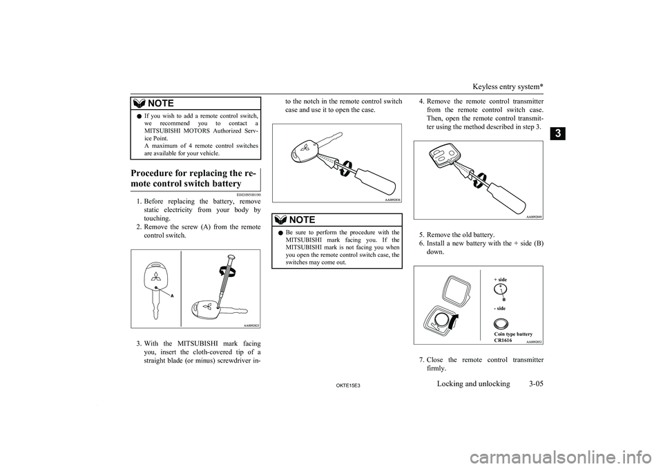
2. Remove the screw (A) from the remote
control switch.
3. With the MITSUBISHI mark facing
you, insert the cloth-covered tip of a
straight blade (or minus) screwdriver in-
to the notch in the remote control switch
case and use it to open the case.NOTEl Be sure to perform the procedure with the
MITSUBISHI mark facing you. If the
MITSUBISHI mark is not facing you when
you open the remote control switch case, the switches may come out.4. Remove the remote control transmitter
from the remote control switch case.
Then, open the remote control transmit-
ter using the method described in step 3.
5. Remove the old battery.
6. Install a new battery with the + side (B)
down.
+ side- sideCoin type battery
CR1616
7. Close the remote control transmitter
firmly.
Keyless entry system*
3-05OKTE15E3Locking and unlocking3
Page 36 of 418
8.Place the remote control transmitter in
the remote control switch case, then se- curely close the remote control switch
case.
9. Attach the screw (A) removed in step 2.
10. Check the keyless entry system to see
that it works.NOTEl You may purchase a replacement battery at
an electric appliance store.
l A
MITSUBISHI MOTORS Authorized
Service Point can replace the battery for you
if you prefer.CAUTIONl When the remote control switch case is
opened, be careful to keep water, dust, etc. out. Also, do not touch the internal compo-
nents.Doors
E00300401584CAUTIONlMake sure the doors are closed: driving with
doors not completely closed is dangerous.
l Never leave children in the vehicle unatten-
ded.CAUTIONl Be careful not to lock the doors while the
key is inside the vehicle.NOTEl To prevent the key from being locked inside
the vehicle, neither the lock knob on the
driver’s door nor the key can be used to lock the driver’s door when it is open.
To lock or unlock with the key
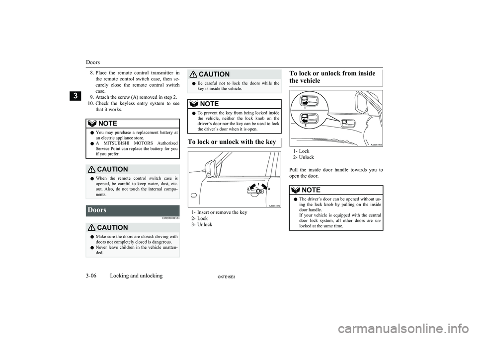
1- Insert or remove the key
2- Lock
3- Unlock
To lock or unlock from inside
the vehicle
1- Lock
2- Unlock
Pull the inside door handle towards you to open the door.
NOTEl The driver’s door can be opened without us-
ing the lock knob by pulling on the inside
door handle.
If your vehicle is equipped with the central door lock system, all other doors are un-
locked at the same time.
Doors
3-06OKTE15E3Locking and unlocking3
Page 39 of 418
WARNINGlBefore operating the electric window con-
trol, make sure that nothing can get trap-
ped (head, hand, finger, etc.).
l Never leave the vehicle without removing
the key.
l Never leave a child (or other person who
might not be capable of safe operation of
the electric window control) in the vehicle alone.
l The child may tamper with the switch at
the risk of its hands or head being trap- ped in the window.Electric window control switch
E00302301431
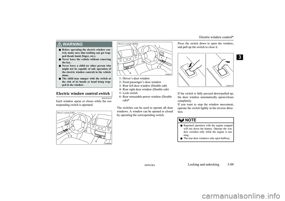
Each window opens or closes while the cor-
responding switch is operated.
Driver’s switch (LHD)Driver’s switch (RHD)
1- Driver’s door window
2- Front passenger’s door window
3- Rear left door window (Double cab)
4- Rear right door window (Double cab)
5- Lock switch
6- Rear retractable power window (Double cab)*
The switches can be used to operate all door
windows. A window can be opened or closed by operating the corresponding switch.
Press the switch down to open the window,
and pull up the switch to close it.
If the switch is fully pressed down/pulled up,
the door window automatically opens/closes
completely.
If you want to stop the window movement,
operate the switch lightly in the reverse direc-
tion.
NOTEl Repeated operation with the engine stopped
will run down the battery. Operate the win-
dow switches only while the engine is run- ning.
l The rear door windows only open halfway.
Electric window control*
3-09OKTE15E3Locking and unlocking3
Page 46 of 418
WARNINGlDo not put head, hands or anything else
out of the sunroof opening while driving
the vehicle.
l Never leave a child (or other person who
might not be capable of safe operation of
the sunroof switch) in the vehicle alone.
l Before operating the sunroof, make sure
that nothing is capable of being trapped
(head, hand, finger, etc.).NOTEl The sunroof stops just before reaching the
fully open position.
If the vehicle is driven with the sunroof in
this position, wind throb is lower than with the sunroof fully open.
l When leaving the vehicle unattended, make
sure you close the sunroof and remove the ignition key.
l Do not try to operate the sunroof if it is fro-
zen closed (after snow fall or during extreme cold).
l Do not sit or place heavy luggage on the
sunroof or roof opening edge.
l Release the switch as soon as the sunroof
reaches the fully open or fully closed posi-
tion.NOTEl If the sunroof does not operate when the
sunroof switch is operated, release the switch and check whether something is trap-
ped by the sunroof. If nothing is trapped, we recommend you to have the sunroof
checked.
l Depending on the model of ski carriers or
roof carriers, the sunroof may make contactwith the carrier when the sunroof is tilted up.Be careful when tilting up the sunroof if
such a ski carrier or a roof carrier is instal-
led.
l Be sure to close the sunroof completely
when washing the vehicle or when leaving
the vehicle.
l Be careful, not to put any wax on the weath-
erstrip (black rubber) around the sunroof opening. If stained with wax, the weather-
strip cannot maintain a weatherproof seal with the sunroof.
l After washing the vehicle or after it has
rained, wipe off any water that is on the sun-
roof before operating it.
l Operating the sunroof repeatedly with the
engine stationary will run down the battery. Operate the sunroof while the engine is run-
ning.
Sunroof*
3-16OKTE15E3Locking and unlocking3
Page 50 of 418
Front seatE0400400012To adjust forward or back-
ward
E00400500824
Manual type
Pull the seat adjusting lever and adjust the seat forward or backward to the desired posi-tion. After adjustment, release the adjusting
lever to lock the seat in position.
WARNINGl To ensure the seat is locked securely, try
to move the seat forward or backward
without using the adjusting lever.Power type
Adjust the seat by operating the switch as in-
dicated by the arrows.
1- Adjustment forward
2- Adjustment backward
NOTEl To prevent the battery from running down,
operate the power type seat with the engine
running.To recline the seatback
E00400601037
Manual type
In order to recline the seatback, lean forward slightly, pull the seatback lock lever up, and
then lean backward to the desired position
and release the lever. The seatback will lock in that position.
CAUTIONl The reclining mechanism of the seatback is
spring loaded, causing it to return to the ver- tical position when the lock lever is operat- ed. When operating the lever, sit close to the
seatback or hold it with your hand to control its return motion.
Front seat
4-04OKTE15E3Seat and seat belts4
Page 51 of 418
Power type
Adjust the seatback angle by operating theswitch as indicated by the arrows.
1- To move to forward direction
2- To recline rearward
NOTEl To prevent the battery from running down,
operate the power type seat with the engine
running.To adjust the seat height (Driv-
er’s seat)*
E00400701113
Manual type
Dial type
To adjust the seat cushion height, turn the di- al as shown in the illustration.
1- To move the seat cushion up
2- To move the seat cushion down
Lever type
Adjust the seat height by repeatedly operat-
ing the lever.
1- Raise
2- Lower
Power type
To adjust the seat height, operate the switch
as indicated by arrows.
NOTEl To prevent the battery from running down,
operate the power type seat with the engine
running.
Front seat
4-05OKTE15E3Seat and seat belts4
Page 92 of 418
Tripmeter
The tripmeter indicates the distance travelled
during a particular trip or period.
There are two tripmeter displays: TRIP
and .
TRIP
can be used to measure the distance
travelled since the current trip began. At the same time, TRIP
can be used to measure
the distance from an intermediate location.
Every time the reset button (C) is pressed
lightly (less than 1 second), the tripmeter dis-
play changes (between TRIP
and ).
Type 1Type 2
To reset the tripmeter
To return the display to “0”, press the reset
button (C) for more than 1 second. Only the currently displayed value will be reset. IfTRIP
is displayed, for example, only
TRIP
will be reset.
NOTEl Display TRIP and
each have a max-
imum distance of 999.9 km (999.9 miles).
l When disconnecting the battery terminal for
a long time, the memory of tripmeter display
TRIP
and are cleared, and the dis-
play returns to “0”.
Fuel gauge
E00500700902
The fuel gauge indicates the fuel level in the
fuel tank when the ignition switch is in the
“ON” position.
F- Full
E- Empty
NOTEl When the engine on diesel-powered vehicles
fails to operate due to running out of fuel, it may sometimes be difficult to start after re-
fueling. This is due to air entering the fuel
system. Therefore, air must be bled from the system. (Refer to “Bleeding the fuel system” on page 8-05.)
Instruments
5-04OKTE15E3Instruments and controls5
Page 97 of 418
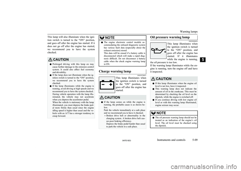
This lamp will also illuminate when the igni-
tion switch is turned to the “ON” position, and goes off after the engine has started. If it
does not go off after the engine has started,
we recommend you to have the system checked.CAUTIONl Prolonged driving with this lamp on may
cause further damage to the emission control
system. It could also affect fuel economy and drivability.
l If the lamp does not illuminate when the ig-
nition switch is turned to the “ON” position, we recommend you to have the system
checked.
l If the lamp illuminates while the engine is
running, avoid driving at high speeds and we recommend you to have the system checked.
During vehicle operation with the lamp illu-
minated, the vehicle may not accelerate
when you depress the accelerator pedal.
When the vehicle is stationary with the lamp illuminated, you must depress the brake ped- al more firmly than usual since the engine
idling speed is higher than usual and the ve- hicle with an A/T has a stronger tendency to
creep forward.NOTEl The engine electronic control module ac-
commodating the onboard diagnostic system has various fault data (especially about the
exhaust emission) stored.
This data will be erased if a battery cable is
disconnected which will make a rapid diag- nosis difficult. Do not disconnect a batterycable when the check engine warning lamp
is ON.Charge warning lamp
E00502700821
This lamp illuminates when
the ignition switch is turnedto the “ON” position, and goes off after the engine has
started.
CAUTIONl If the lamp comes on while the engine is
running, the probable cause is as shown be-low.
Park the vehicle immediately at a safe place
and we recommend you to have it checked.
• Broken drive belt or abnormality in the
charging system. A broken drive belt cau-
ses poor braking efficiency.
Depress the brake pedal harder than usual
to park the vehicle in a safe place.Oil pressure warning lamp
E00502800620
This lamp illuminates when
the ignition switch is turnedto the “ON” position, and goes off after the engine has
started. If it illuminates
while the engine is running,
the oil pressure is too low.
If the warning lamp illuminates while the en- gine is running, turn the engine off and have
it inspected.
CAUTIONl If this lamp illuminates when the engine oil
level is not low, have it inspected.
l This warning lamp does not indicate the
amount of oil in the crankcase. This must be determined by checking the oil level on the
dipstick, while the engine is switched off.
l If you continue driving with low engine oil
level or with this warning lamp illuminated,
engine seizure may occur.NOTEl The oil pressure warning lamp should not be
treated as an indication of the engine’s oil
level. The oil level must be checked using
the dipstick.
Warning lamps
5-09OKTE15E3Instruments and controls5
Page 103 of 418
NOTElWhen the driving range is 50 km (30 miles)
or less, the display shows “----”.
When it is 3,000 km (2,000 miles) or more,
“3,000 km” or “2,000 miles” will be shown.
l When the driving range cannot be measured,
the display shows “----”.
l The driving range is shown based on the ac-
cumulated fuel consumption data, however,
may be changed depending on the driving condition (road condition, driving behavior, etc.). If the battery terminals are disconnec-
ted, the accumulated fuel consumption data will be erased. It is recommended to use the indication as reference.
l When the vehicle is fueled, the driving range
will be updated. However, if the amount of
fueling is small, the indication may not be
correct. Therefore, fill up the tank as much as possible in case of fueling.
l When the vehicle is stopped on a steep
slope, the value of the driving range may in-
crease. This is caused by the fuel movement inside the tank on the slope and is not
deemed as a failure.Resetting the driving range
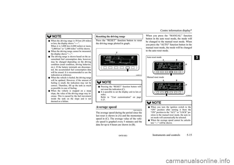
Press the “RESET” function button to reset
the driving range plotted in graph.
NOTEl Pressing the “RESET” function button will
not reset the indication (C).
l It is possible to set the display unit to km or
miles.
Refer to “User customization” on page 5-27.Average speed
E00518400126
The average speed during the period since the
last reset is shown in (A) and the momentary speed in (C). The average value of the vehi-cle speed is graphed every 5 minutes and the
data for up to 4 hours are shown in (B).
When you press the “MANUAL” function
button in the auto reset mode, the mode will
be changed to the manual reset mode. When you press the “AUTO” function button in themanual reset mode, the mode will be changed
to the auto reset mode.NOTEl When you turn the ignition switch to the
“ON” position after turning it from the “ON” position to the “ACC” or “LOCK” po-
sition in the manual reset mode, the auto re- set mode will automatically be selected.
l When the average speed cannot be calcula-
ted, “---” will be shown.
Centre information display*
5-15OKTE15E3Instruments and controls5 Auto reset modeManual reset mode