belt MITSUBISHI LANCER 2005 User Guide
[x] Cancel search | Manufacturer: MITSUBISHI, Model Year: 2005, Model line: LANCER, Model: MITSUBISHI LANCER 2005Pages: 788, PDF Size: 45.98 MB
Page 105 of 788
IGNITION SYSTEM
ENGINE ELECTRICAL16-41
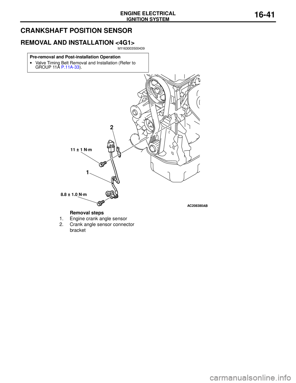
CRANKSHAFT POSITION SENSOR
REMOVAL AND INSTALLATION <4G1>
M1163003500439
Pre-removal and Post-installation Operation
•Valve Timing Belt Removal and Installation (Refer to
GROUP 11A P.11A-33).
AC208380AB
12
11 ± 1 N·m
8.8 ± 1.0 N·m
Removal steps
1. Engine crank angle sensor
2. Crank angle sensor connector
bracket
Page 106 of 788
IGNITION SYSTEM
ENGINE ELECTRICAL16-42
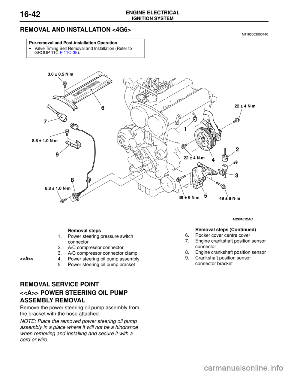
REMOVAL AND INSTALLATION <4G6>M1163003500440
REMOVAL SERVICE POINT
<> POWER STEERING OIL PUMP
ASSEMBLY REMOVAL
Remove the power steering oil pump assembly from
the bracket with the hose attached.
NOTE: Place the removed power steering oil pump
assembly in a place where it will not be a hindrance
when removing and installing and secure it with a
cord or wire.
Pre-removal and Post-installation Operation
•Valve Timing Belt Removal and Installation (Refer to
GROUP 11C P.11C-35).
AC301612
8.8 ± 1.0 N·m
8
8.8 ± 1.0 N·m
9
1
22 ± 4 N·m
4
2
3
49 ± 9 N·m49 ± 9 N·m5
22 ± 4 N·m
3.0 ± 0.5 N·m
6
7
AC
Removal steps
1. Power steering pressure switch
connector
2. A/C compressor connector
3. A/C compressor connector clamp
<>4. Power steering oil pump assembly
5. Power steering oil pump bracket6. Rocker cover centre cover
7. Engine crankshaft position sensor
connector
8. Engine crankshaft position sensor
9. Crankshaft position sensor
connector bracket Removal steps (Continued)
Page 235 of 788
37-1
GROUP 37
POWER STEERING
CONTENTS
GENERAL INFORMATION . . . . . . . .37-3
SERVICE SPECIFICATIONS . . . . . . .37-6
LUBRICANTS . . . . . . . . . . . . . . . . . .37-7
SEALANTS . . . . . . . . . . . . . . . . . . . .37-7
SPECIAL TOOLS . . . . . . . . . . . . . . . .37-8
ON-VEHICLE SERVICE . . . . . . . . . . .37-11
STEERING WHEEL FREE PLAY
CHECK . . . . . . . . . . . . . . . . . . . . . . . . . . . . 37-11
STEERING ANGLE CHECK . . . . . . . . . . . . 37-11
TIE ROD END BALL JOINT TURNING
TORQUE CHECK . . . . . . . . . . . . . . . . . . . . 37-12
STATIONARY STEERING EFFORT
CHECK . . . . . . . . . . . . . . . . . . . . . . . . . . . . 37-12
STEERING WHEEL RETURN TO
CENTRE CHECK . . . . . . . . . . . . . . . . . . . . 37-13DRIVE BELT TENSION CHECK . . . . . . . . . 37-13
FLUID LEVEL CHECK . . . . . . . . . . . . . . . . 37-13
FLUID REPLACEMENT . . . . . . . . . . . . . . . 37-13
POWER STEERING SYSTEM AIR
BLEEDING . . . . . . . . . . . . . . . . . . . . . . . . . 37-13
OIL PUMP PRESSURE TEST . . . . . . . . . . 37-14
POWER STEERING PRESSURE
SWITCH CHECK . . . . . . . . . . . . . . . . . . . . . 37-15
TIE ROD END BALL JOINT DUST COVER
CHECK . . . . . . . . . . . . . . . . . . . . . . . . . . . . 37-15
STEERING COLUMN SHAFT
ASSEMBLY SHOCK ABSORBING
MECHANISM CHECK . . . . . . . . . . . . . . . . . 37-15
STEERING WHEEL* . . . . . . . . . . . . . .37-17
REMOVAL AND INSTALLATION
REMOVAL AND INSTALLATION
Continued on next page
WARNINGS REGARDING SERVICING OF SUPPLEMENTAL RESTRAINT SYSTEM (SRS) EQUIPPED VEHICLES
WARNING
•Improper service or maintenance of any component of the SRS, or any SRS-related component, can lead to
personal injury or death to service personnel (from inadvertent firing of the air bag) or to the driver and
paassenger (from rendering the SRS inoperative).
•Service or maintenance of any SRS component or SRS-related component must be performed only at an
authorized MITSUBISHI dealer.
•MITSUBISHI dealer personnel must thoroughly review this manual, and especially its GROUP 52B - Supplemental
Restraint System (SRS) before beginning any service or maintenance of any component of the SRS or any
SRS-related component.
NOTE
The SRS includes the following components: SRS air bag control unit, SRS warning light, front impact sensors, air bag module,
clock spring, and interconnecting wiring. Other SRS-related components (that may have to be removed/installed in connection
with SRS service or maintenance) are indicated in the table of contents by an asterisk (*).
Page 247 of 788
ON-VEHICLE SERVICE
POWER STEERING37-13
STEERING WHEEL RETURN TO CENTRE
CHECK
M1372001800317
Conduct a road test:
1. Make both gradual and sudden turns and check
the steering wheel return.
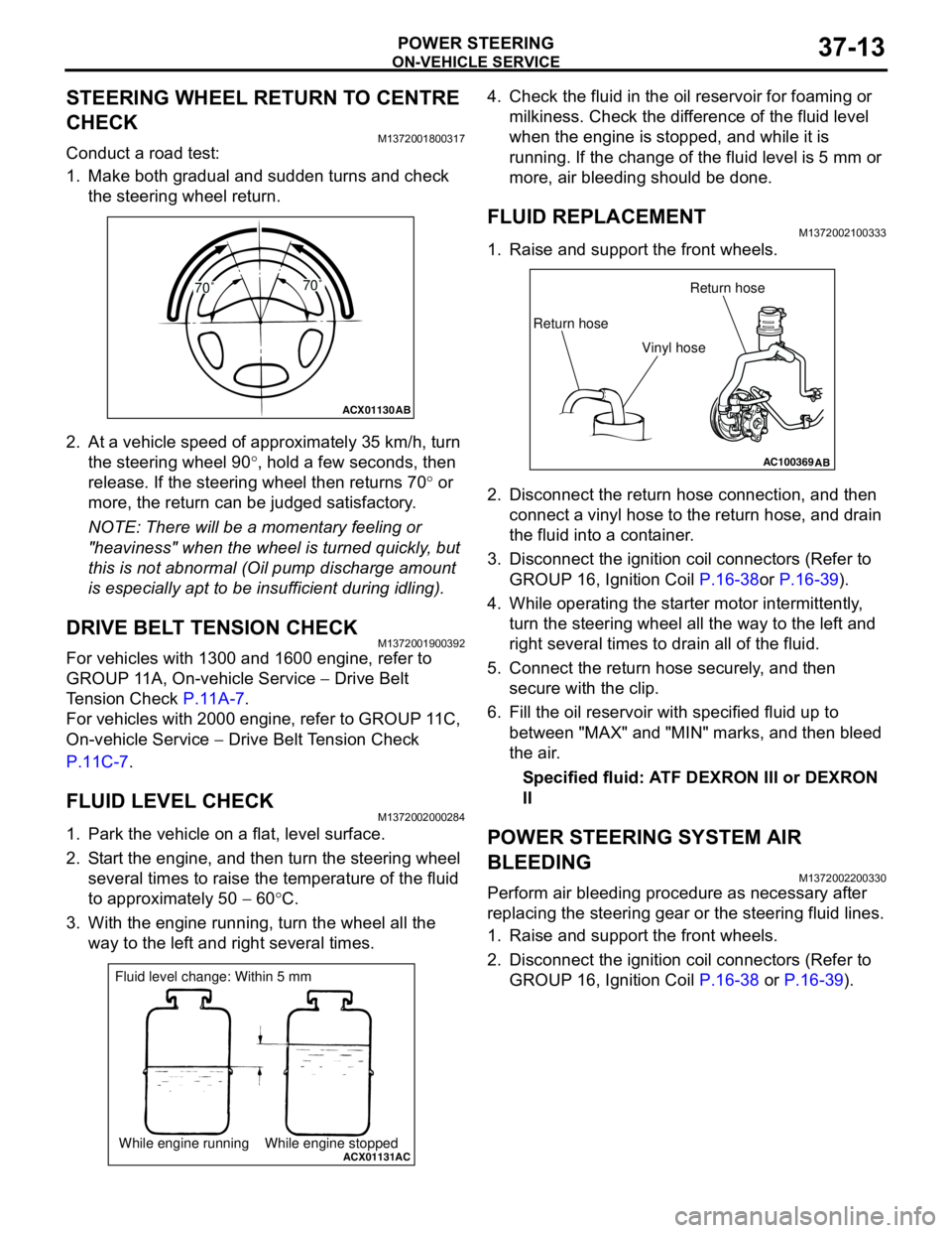
2. At a vehicle speed of approximately 35 km/h, turn
the steering wheel 90°, hold a few seconds, then
release. If the steering wheel then returns 70° or
more, the return can be judged satisfactory.
NOTE: There will be a momentary feeling or
"heaviness" when the wheel is turned quickly, but
this is not abnormal (Oil pump discharge amount
is especially apt to be insufficient during idling).
DRIVE BELT TENSION CHECKM1372001900392
For vehicles with 1300 and 1600 engine, refer to
GROUP 11A, On-vehicle Service − Drive Belt
Tension Check P.11A-7.
For vehicles with 2000 engine, refer to GROUP 11C,
On-vehicle Service − Drive Belt Tension Check
P.11C-7.
FLUID LEVEL CHECKM1372002000284
1. Park the vehicle on a flat, level surface.
2. Start the engine, and then turn the steering wheel
several times to raise the temperature of the fluid
to approximately 50 − 60°C.
3. With the engine running, turn the wheel all the
way to the left and right several times.4. Check the fluid in the oil reservoir for foaming or
milkiness. Check the difference of the fluid level
when the engine is stopped, and while it is
running. If the change of the fluid level is 5 mm or
more, air bleeding should be done.
FLUID REPLACEMENTM1372002100333
1. Raise and support the front wheels.
2. Disconnect the return hose connection, and then
connect a vinyl hose to the return hose, and drain
the fluid into a container.
3. Disconnect the ignition coil connectors (Refer to
GROUP 16, Ignition Coil P.16-38or P.16-39).
4. While operating the starter motor intermittently,
turn the steering wheel all the way to the left and
right several times to drain all of the fluid.
5. Connect the return hose securely, and then
secure with the clip.
6. Fill the oil reservoir with specified fluid up to
between "MAX" and "MIN" marks, and then bleed
the air.
Specified fluid: ATF DEXRON III or DEXRON
II
POWER STEERING SYSTEM AIR
BLEEDING
M1372002200330
Perform air bleeding procedure as necessary after
replacing the steering gear or the steering fluid lines.
1. Raise and support the front wheels.
2. Disconnect the ignition coil connectors (Refer to
GROUP 16, Ignition Coil P.16-38 or P.16-39).
ACX01130
AB
70˚70˚
ACX01131While engine running While engine stoppedAC
Fluid level change: Within 5 mm
AC100369AB
Return hoseReturn hose
Vinyl hose
Page 271 of 788
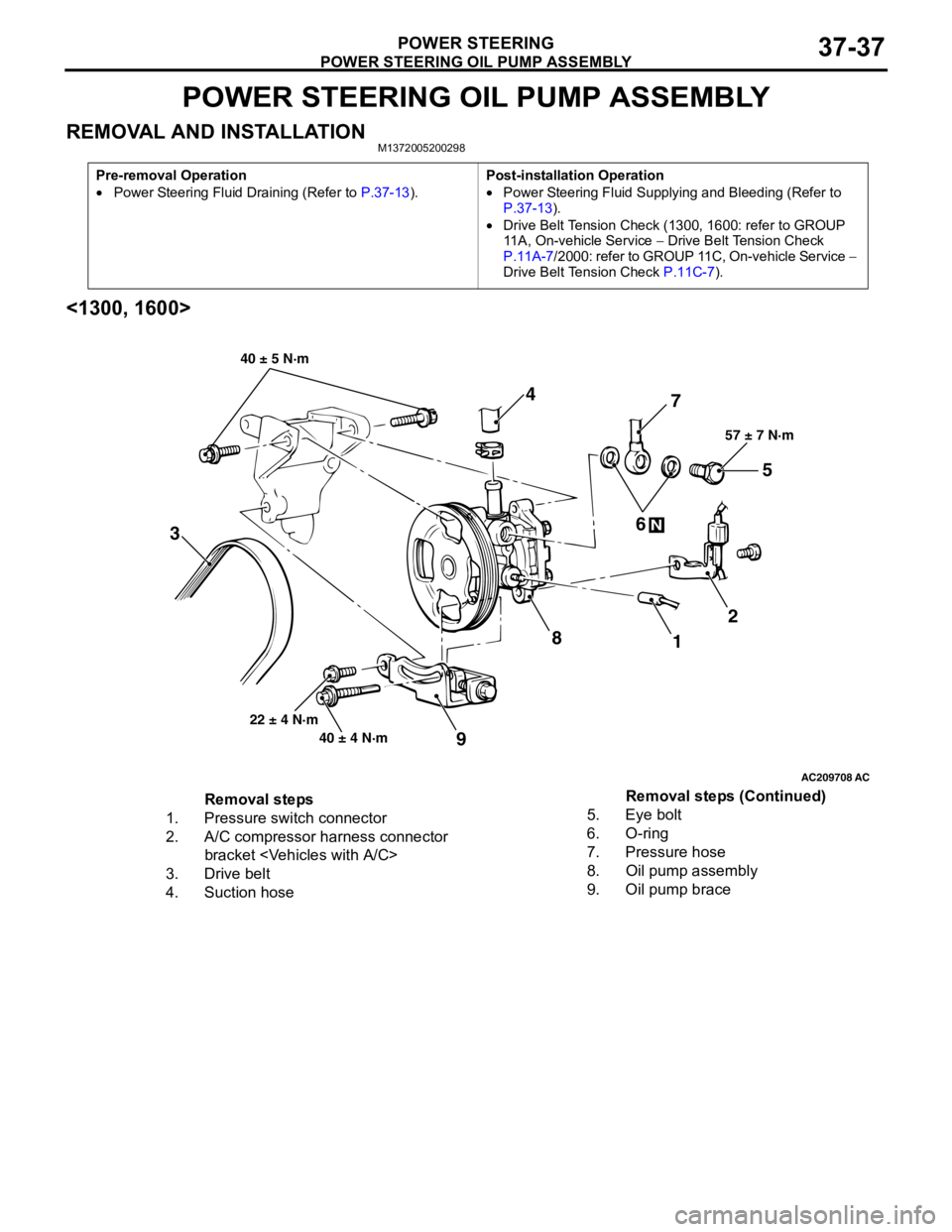
POWER STEERING OIL PUMP ASSEMBLY
POWER STEERING37-37
POWER STEERING OIL PUMP ASSEMBLY
REMOVAL AND INSTALLATIONM1372005200298
<1300, 1600>
Pre-removal Operation
•Power Steering Fluid Draining (Refer to P.37-13).Post-installation Operation
•Power Steering Fluid Supplying and Bleeding (Refer to
P.37-13).
•Drive Belt Tension Check (1300, 1600: refer to GROUP
11A, On-vehicle Service − Drive Belt Tension Check
P.11A-7/2000: refer to GROUP 11C, On-vehicle Service −
Drive Belt Tension Check P.11C-7).
AC209708
87
12 34
5
6
57 ± 7 N·m
40 ± 4 N·m 22 ± 4 N·m
N
9
40 ± 5 N·m
AC
Removal steps
1. Pressure switch connector
2. A/C compressor harness connector
bracket
3. Drive belt
4. Suction hose5. Eye bolt
6. O-ring
7. Pressure hose
8. Oil pump assembly
9. Oil pump braceRemoval steps (Continued)
Page 272 of 788
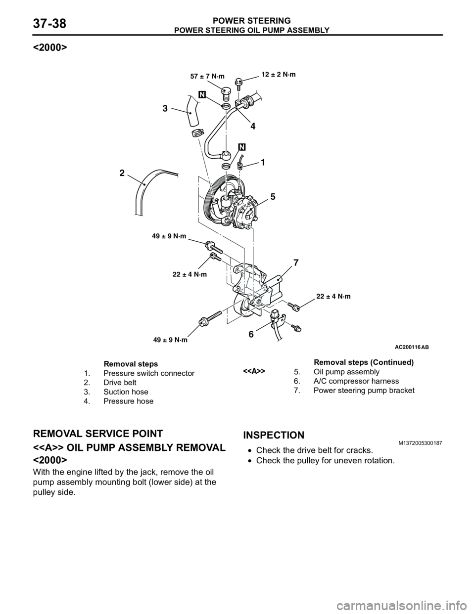
POWER STEERING OIL PUMP ASSEMBLY
POWER STEERING37-38
<2000>
REMOVAL SERVICE POINT
<> OIL PUMP ASSEMBLY REMOVAL
<2000>
With the engine lifted by the jack, remove the oil
pump assembly mounting bolt (lower side) at the
pulley side.
INSPECTIONM1372005300187
•Check the drive belt for cracks.
•Check the pulley for uneven rotation.
AC200116
AB
22 ± 4 N·m 12 ± 2 N·m
22 ± 4 N·m 49 ± 9 N·m57 ± 7 N·m
1
5 4 3
6 2
7
49 ± 9 N·m
Removal steps
1. Pressure switch connector
2. Drive belt
3. Suction hose
4. Pressure hose<>5. Oil pump assembly
6. A/C compressor harness
7. Power steering pump bracketRemoval steps (Continued)
Page 311 of 788
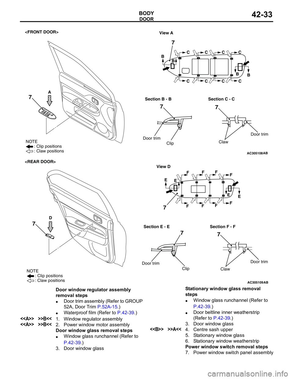
DOOR
BODY42-33
AC305108
NOTE
: Clip positions
: Claw positions
View A
B
B
B
B C
CC
CC
CC
C
Section B - B
Door trim
ClipSection C - C
AB
Door trim
Claw
7
7
7 7
A
AC305109
NOTE
: Clip positions
: Claw positions
E
E
E
E F
FF
FF
FF
F
Section E - EView D
Door trim
ClipSection F - F
Door trim
Claw
D
7
7 7
AB
7
Door window regulator assembly
removal steps
•Door trim assembly (Refer to GROUP
52A, Door Trim P.52A-15.)
•Waterproof film (Refer to P.42-39.)
<> >>B<<1. Window regulator assembly
<> >>B<<2. Power window motor assembly
Door window glass removal steps
•Window glass runchannel (Refer to
P.42-39.)
3. Door window glassStationary window glass removal
steps
•Window glass runchannel (Refer to
P.42-39.)
•Door beltline inner weatherstrip
(Refer to P.42-39.)
3. Door window glass<> >>A<<4. Centre sash upper
5. Stationary window glass
6. Stationary window weatherstrip
Power window switch removal steps
7. Power window switch panel assembly
Page 317 of 788
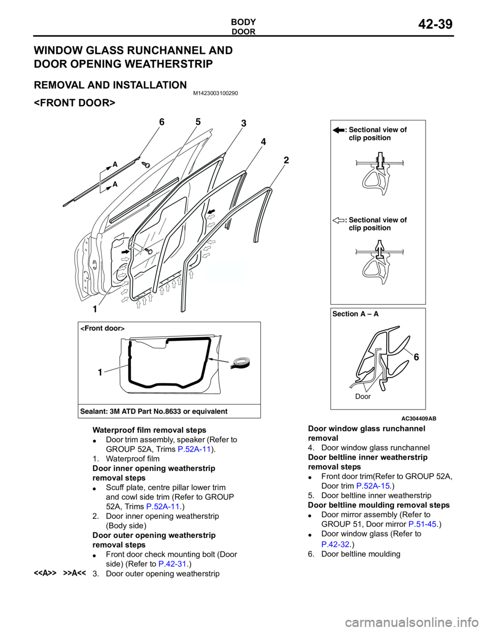
DOOR
BODY42-39
WINDOW GLASS RUNCHANNEL AND
DOOR OPENING WEATHERSTRIP
REMOVAL AND INSTALLATIONM1423003100290
AC304409AB
Section A – A
Sealant: 3M ATD Part No.8633 or equivalentDoor
: Sectional view of
clip position
: Sectional view of
clip position
6 2
1
4
365
A A
1
Waterproof film removal steps
•Door trim assembly, speaker (Refer to
GROUP 52A, Trims P.52A-11).
1. Waterproof film
Door inner opening weatherstrip
removal steps
•Scuff plate, centre pillar lower trim
and cowl side trim (Refer to GROUP
52A, Trims P.52A-11.)
2. Door inner opening weatherstrip
(Body side)
Door outer opening weatherstrip
removal steps
•Front door check mounting bolt (Door
side) (Refer to P.42-31.)
<> >>A<<3. Door outer opening weatherstripDoor window glass runchannel
removal
4. Door window glass runchannel
Door beltline inner weatherstrip
removal steps
•Front door trim(Refer to GROUP 52A,
Door trim P.52A-15.)
5. Door beltline inner weatherstrip
Door beltline moulding removal steps
•Door mirror assembly (Refer to
GROUP 51, Door mirror P.51-45.)
•Door window glass (Refer to
P.42-32.)
6. Door beltline moulding
Page 318 of 788
DOOR
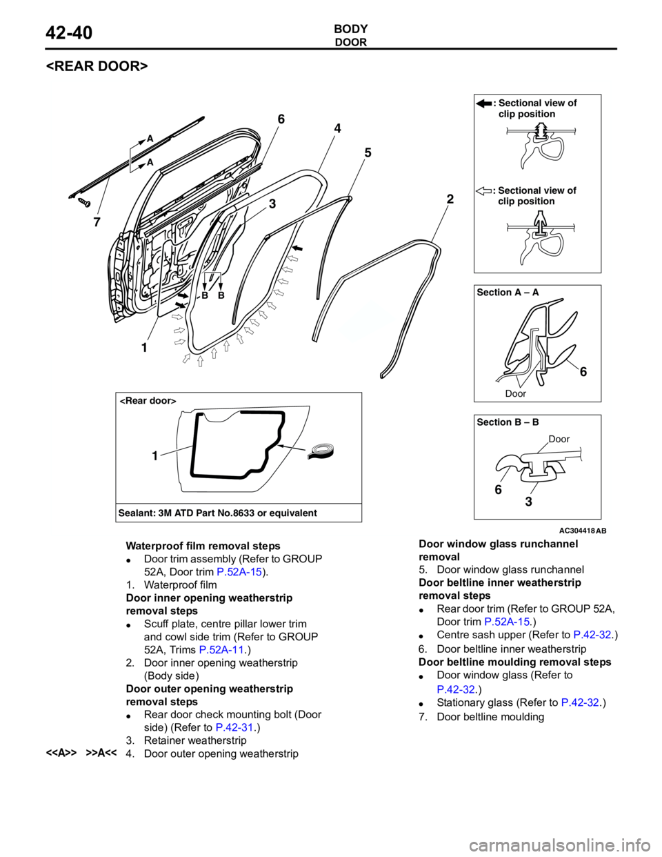
BODY42-40
AC304418AB
Section A – A
Door
: Sectional view of
clip position
: Sectional view of
clip position
6 2 4
5
7
A A
3
Section B – B
Door
6
3
6
BB
Sealant: 3M ATD Part No.8633 or equivalent
1
1
Waterproof film removal steps
•Door trim assembly (Refer to GROUP
52A, Door trim P.52A-15).
1. Waterproof film
Door inner opening weatherstrip
removal steps
•Scuff plate, centre pillar lower trim
and cowl side trim (Refer to GROUP
52A, Trims P.52A-11.)
2. Door inner opening weatherstrip
(Body side)
Door outer opening weatherstrip
removal steps
•Rear door check mounting bolt (Door
side) (Refer to P.42-31.)
3. Retainer weatherstrip
<> >>A<<4. Door outer opening weatherstripDoor window glass runchannel
removal
5. Door window glass runchannel
Door beltline inner weatherstrip
removal steps
•Rear door trim (Refer to GROUP 52A,
Door trim P.52A-15.)
•Centre sash upper (Refer to P.42-32.)
6. Door beltline inner weatherstrip
Door beltline moulding removal steps
•Door window glass (Refer to
P.42-32.)
•Stationary glass (Refer to P.42-32.)
7. Door beltline moulding
Page 486 of 788
55-2
ON-VEHICLE SERVICE . . . . . . . . . . .55-69
SIGHT GLASS REFRIGERANT
LEVEL TEST . . . . . . . . . . . . . . . . . . . . . . . . 55-69
MAGNETIC CLUTCH TEST . . . . . . . . . . . . 55-69
COMPRESSOR DRIVE BELT
ADJUSTMENT . . . . . . . . . . . . . . . . . . . . . . 55-69
DUAL PRESSURE SWITCH CHECK . . . . . 55-69
CHARGING . . . . . . . . . . . . . . . . . . . . . . . . . 55-70
CORRECTING LOW REFRIGERANT LEVEL
IN CASE THE SERVICE CAN IN USED. . . 55-72
DISCHARGING SYSTEM . . . . . . . . . . . . . . 55-72
REFILLING OF OIL IN THE A/C
SYSTEM . . . . . . . . . . . . . . . . . . . . . . . . . . . 55-72
PERFORMANCE TEST . . . . . . . . . . . . . . . 55-73
REFRIGERANT LEAK REPAIR
PROCEDURE . . . . . . . . . . . . . . . . . . . . . . . 55-74
COMPRESSOR NOISE CHECK . . . . . . . . 55-74
POWER RELAY CHECK . . . . . . . . . . . . . . 55-75
IDLE-UP OPERATION CHECK . . . . . . . . . 55-76
CLEAN AIR FILTER REPLACEMENT
PROCEDURE . . . . . . . . . . . . . . . . . . . . . . . 55-76
HEATER CONTROL ASSEMBLY AND A/C
SWITCH . . . . . . . . . . . . . . . . . . . . . . .55-77
REMOVAL AND INSTALLATION . . . . . . . . 55-77
INSPECTION . . . . . . . . . . . . . . . . . . . . . . . 55-79
DISASSEMBLY AND REASSEMBLY . . . . . 55-79
HEATER UNIT, HEATER CORE,
BLOWER ASSEMBLY AND
EVAPORATOR UNIT* . . . . . . . . . . . .55-81
REMOVAL AND INSTALLATION . . . . . . . . 55-81
HEATER UNIT . . . . . . . . . . . . . . . . . . . . . . 55-82
DISASSEMBLY AND REASSEMBLY
DISASSEMBLY AND ASSEMBLY
BLOWER ASSEMBLY . . . . . . . . . . . . . . . . 55-84
DISASSEMBLY AND REASSEMBLY . . . . . 55-84
BLOWERMOTOR, RESISTOR AND
OUTSIDE/INSIDE AIR SELECTION
DAMPER CONTROL MOTOR . . . . . .55-85
REMOVAL AND INSTALLATION . . . . . . . . 55-85
INSPECTION . . . . . . . . . . . . . . . . . . . . . . . . 55-86
EVAPORATOR ASSEMBLY . . . . . . .55-88
REMOVAL AND INSTALLATION
REMOVAL AND INSTALLATION
INSPECTION . . . . . . . . . . . . . . . . . . . . . . . . 55-90
COMPRESSOR ASSEMBLY AND
TENSION PULLEY . . . . . . . . . . . . . . .55-91
REMOVAL AND INSTALLATION . . . . . . . . 55-91
INSPECTION . . . . . . . . . . . . . . . . . . . . . . . . 55-93
DISASSEMBLY AND REASSEMBLY . . . . . 55-94
INSPECTION . . . . . . . . . . . . . . . . . . . . . . . . 55-95
CONDENSER AND CONDENSER
FAN MOTOR . . . . . . . . . . . . . . . . . . . .55-96
REMOVAL AND INSTALLATION . . . . . . . . 55-96
INSPECTION . . . . . . . . . . . . . . . . . . . . . . . . 55-97
REFRIGERANT LINE . . . . . . . . . . . . .55-98
REMOVAL AND INSTALLATION
REMOVAL AND INSTALLATION
DUCTS . . . . . . . . . . . . . . . . . . . . . . . .55-101
REMOVAL AND INSTALLATION . . . . . . . . 55-101
VENTILATORS . . . . . . . . . . . . . . . . . .55-102
REMOVAL AND INSTALLATION . . . . . . . . 55-102