instrument panel MITSUBISHI LANCER 2005 User Guide
[x] Cancel search | Manufacturer: MITSUBISHI, Model Year: 2005, Model line: LANCER, Model: MITSUBISHI LANCER 2005Pages: 788, PDF Size: 45.98 MB
Page 565 of 788
HEATER UNIT, HEATER CORE, BLOWER ASSEMBLY AND EVAPORATOR UNIT
HEATER, AIR CONDITIONER AND VENTILATION55-81
HEATER UNIT, HEATER CORE, BLOWER ASSEMBLY
AND EVAPORATOR UNIT
REMOVAL AND INSTALLATION
M1552011600457
Pre-removal and Post-installation Operation
•Refrigerant draining and Refilling (Refer to Charging
P.55-70 and Discharging P.55-72).
•Engine coolant Draining and Refilling (Refer to GROUP
14, On vehicles service P.14-22).
•Instrument Panel Removal and Installation (Refer to
GROUP 52A, Instrument Panel P.52A-2).
•Air cleaner cover and air flow sensor assembly Removal
and Installation (Refer to GROUP 15, Air cleaner P.15-3).
•Rear console assembly Removal and Installation (Refer
to GROUP 52A, Rear console assembly P.52A-8).
•Front floor console assembly Removal and Installation
(Refer to GROUP 52A, Front floor console assembly
P.52A-6).
•Front seat assembly Removal and Installation (Refer to
GROUP 52A, Front seat assembly P.52A-24).
AC304861
1
2
3
4 5
6
7
8
N
9
AB
12 ± 2 N·m
6, 7O ring -Pipe coupling
A/C compressor oil:
SUN PAG 56
44 ± 10 N·m
44 ± 10 N·m
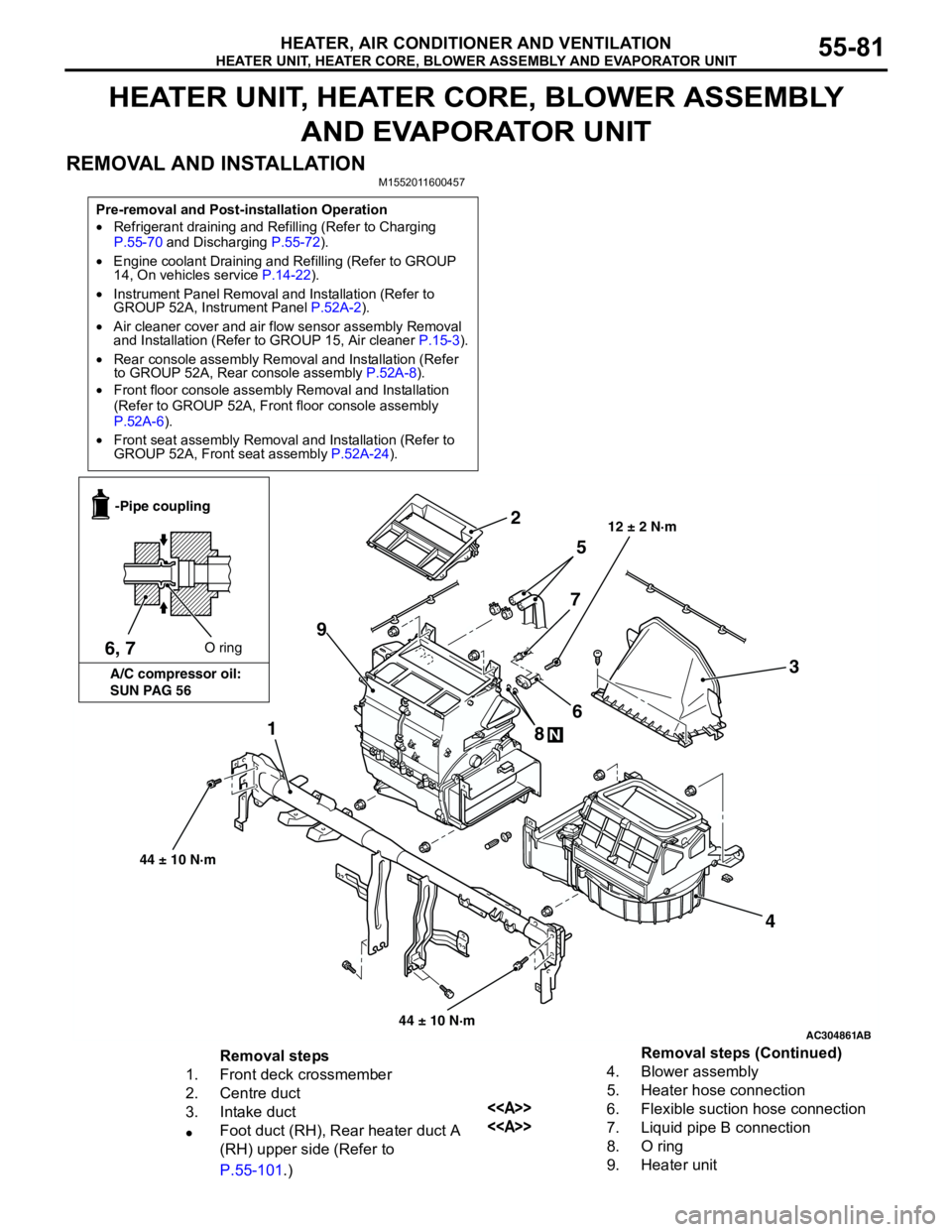
Removal steps
1. Front deck crossmember
2. Centre duct
3. Intake duct
•Foot duct (RH), Rear heater duct A
(RH) upper side (Refer to
P.55-101.)4. Blower assembly
5. Heater hose connection
<>6. Flexible suction hose connection
<>7. Liquid pipe B connection
8. O ring
9. Heater unitRemoval steps (Continued)
Page 569 of 788
BLOWERMOTOR, RESISTOR AND OUTSIDE/ INSIDE AIR SELECTION DAMPER CONTROL MOTOR
HEATER, AIR CONDITIONER AND VENTILATION55-85
BLOWERMOTOR, RESISTOR AND OUTSIDE/
INSIDE AIR SELECTION DAMPER CONTROL MOTOR
REMOVAL AND INSTALLATION
M1551002800320
AC304885AB
2
31
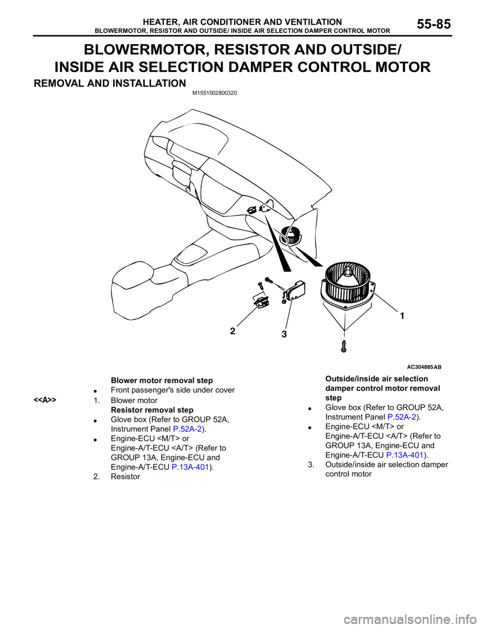
Blower motor removal step
•Front passenger's side under cover
<>1. Blower motor
Resistor removal step
•Glove box (Refer to GROUP 52A,
Instrument Panel P.52A-2).
•Engine-ECU
Engine-A/T-ECU (Refer to
GROUP 13A, Engine-ECU and
Engine-A/T-ECU P.13A-401).
2. ResistorOutside/inside air selection
damper control motor removal
step
•Glove box (Refer to GROUP 52A,
Instrument Panel P.52A-2).
•Engine-ECU
Engine-A/T-ECU (Refer to
GROUP 13A, Engine-ECU and
Engine-A/T-ECU P.13A-401).
3. Outside/inside air selection damper
control motor
Page 572 of 788
EVAPORATOR ASSEMBLY
HEATER, AIR CONDITIONER AND VENTILATION55-88
EVAPORATOR ASSEMBLY
REMOVAL AND INSTALLATION
REMOVAL SERVICE POINT
<> FLEXIBLE SUCTION HOSE AND
LIQUID PIPE B DISCONNECTION
CAUTION
As the compressor oil and receiver are highly
moisture absorbent, use a non-porous material
to plug the hose and nipples.
To prevent the entry of dust or other foreign bodies,
plug the dismantled hose and the nipples of the
expansion valves.
Pre-removal and Post-installation Operation
•Refrigerant draining and Refilling (Refer to Charging
P.55-70 and Discharging P.55-72).
•Air cleaner assembly <1300,1600> or Air cleaner and air
cleaner air flow sensor assembly <2000> Removal and
Installation (Refer to GROUP 15, Air cleaner P.15-3).
Y2346AU
1, 2, 4, 7
A/C compressor oil:
SUN PAG 56O ring
-Pipe coupling
2
101
3 4
7
6
5 98
8
12 ± 2 N·m
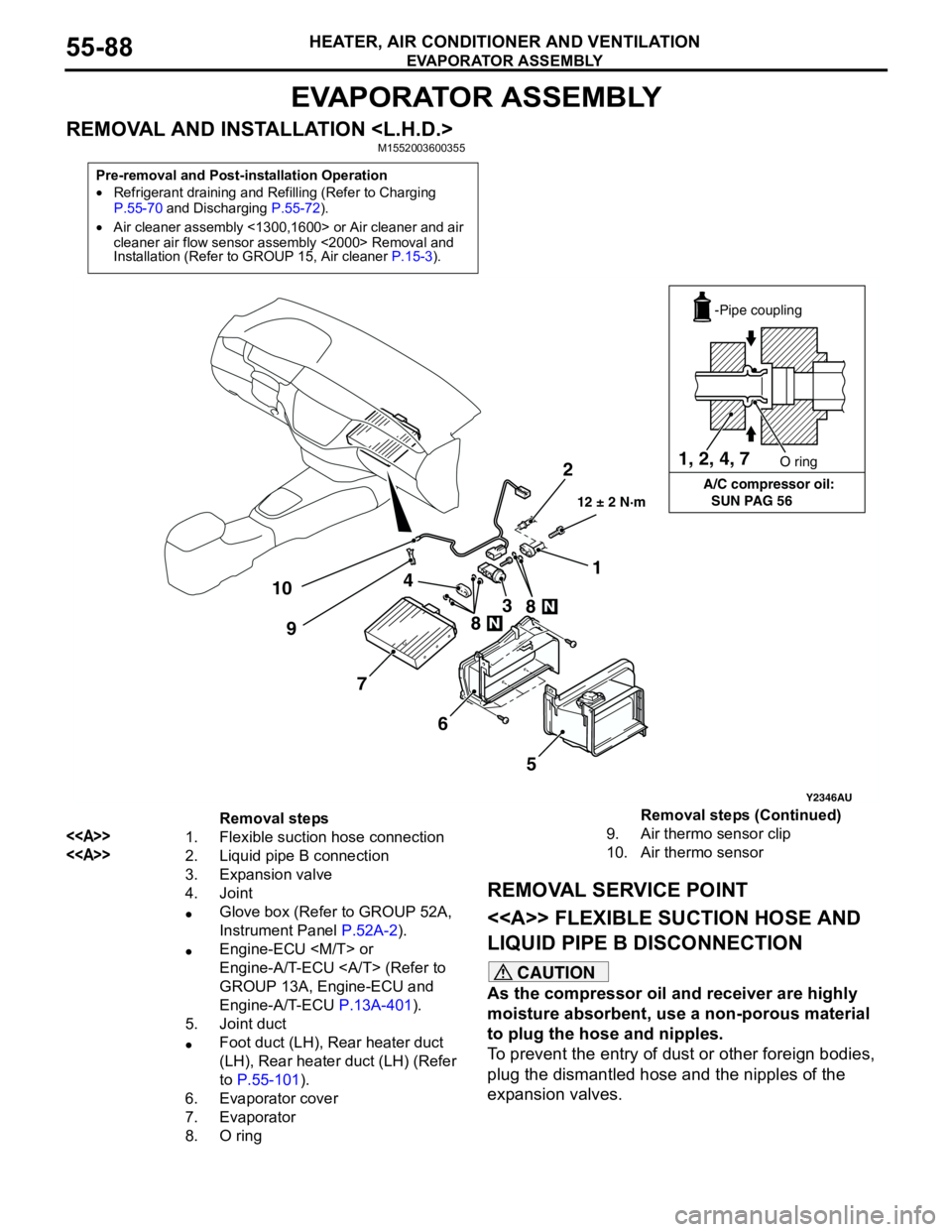
Removal steps
<>1. Flexible suction hose connection
<>2. Liquid pipe B connection
3. Expansion valve
4. Joint
•Glove box (Refer to GROUP 52A,
Instrument Panel P.52A-2).
•Engine-ECU
Engine-A/T-ECU (Refer to
GROUP 13A, Engine-ECU and
Engine-A/T-ECU P.13A-401).
5. Joint duct
•Foot duct (LH), Rear heater duct
(LH), Rear heater duct (LH) (Refer
to P.55-101).
6. Evaporator cover
7. Evaporator
8. O ring 9. Air thermo sensor clip
10. Air thermo sensorRemoval steps (Continued)
Page 573 of 788
EVAPORATOR ASSEMBLY
HEATER, AIR CONDITIONER AND VENTILATION55-89
REMOVAL AND INSTALLATION
Pre-removal and Post-installation Operation
•Refrigerant draining and Refilling (Refer to Charging
P.55-70 and Discharging P.55-72).
•Air cleaner assembly <1300,1600> or Air cleaner and air
cleaner air flow sensor assembly <2000> Removal and
Installation (Refer to GROUP 15, Air cleaner P.15-3).
AC304886AB
12 ± 2 N·m
7
7
2
1
9
8
6
5
4 3 1, 2, 6
A/C compressor oil:
SUN PAG 56O ring
-Pipe coupling
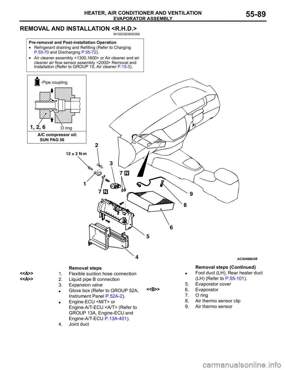
Removal steps
<>1. Flexible suction hose connection
<>2. Liquid pipe B connection
3. Expansion valve
•Glove box (Refer to GROUP 52A,
Instrument Panel P.52A-2).
•Engine-ECU
Engine-A/T-ECU (Refer to
GROUP 13A, Engine-ECU and
Engine-A/T-ECU P.13A-401).
4. Joint duct•Foot duct (LH), Rear heater duct
(LH) (Refer to P.55-101).
5. Evaporator cover
<>6. Evaporator
7. O ring
8. Air thermo sensor clip
9. Air thermo sensorRemoval steps (Continued)
Page 585 of 788
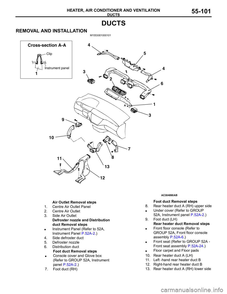
DUCTS
HEATER, AIR CONDITIONER AND VENTILATION55-101
DUCTS
REMOVAL AND INSTALLATIONM1553001000101
AC304890
7
8
13
12 11 109364 5 4
3
2
1
AB A
A
Clip
Instrument panel
1 Cross-section A-A
Air Outlet Removal steps
1. Centre Air Outlet Panel
2. Centre Air Outlet
3. Side Air Outlet
Defroster nozzle and Distribution
duct Removal steps
•Instrument Panel (Refer to 52A,
Instrument Panel P.52A-2.)
4. Side defroster duct
5. Defroster nozzle
6. Distribution duct
Foot duct Removal steps
•Console cover and Glove box
(Refer to GROUP 52A, Instrument
panel P.52A-2.)
7. Foot duct (RH)8. Rear heater duct A (RH) upper side
•Under cover (Refer to GROUP
52A, Instrument panel P.52A-2.)
9. Foot duct (LH)
Rear heater duct Removal steps
•Front floor console (Refer to
GROUP 52A, Front floor console
assembly P.52A-6.)
•Front seat (Refer to GROUP 52A -
Front seat assembly P.52A-24.)
•Floor carpet and Floor pads
10. Rear heater duct A (LH)
11. Left -hand rear heater duct B
12. Right-hand rear heater duct B
13. Rear heater duct A (RH) lower sideFoot duct Removal steps
Page 608 of 788

OVERALL CONFIGURATION DIAGRAM
CONFIGURATION DIAGRAMS80-2
OVERALL CONFIGURATION DIAGRAM
OVERALL WIRING DIAGRAM
NOTE: .
1. This illustration shows only major wiring harnesses.
2. *: also equipped at the right side.
AC301175
AB
Front wiring
harness (RH)Control wiring
harnessInstrument panel
wiring harnessRoof wiring
harnessFloor wiring
harness (RH)
Battery wiring
harnessFront wiring
harness (LH)Front door
wiring harness Floor wiring
harness (LH)Fuel wiring
harnessRear door
wiring harness
Front bumper
wiring harness
Rear bumper
wiring harness
**
Page 609 of 788

OVERALL CONFIGURATION DIAGRAM
CONFIGURATION DIAGRAMS80-3
OVERALL WIRING DIAGRAM
NOTE: .
1. This illustration shows only major wiring harnesses.
2. *: also equipped at the right side.
AC301176AB
Front wiring
harness (RH)Control wiring
harnessInstrument panel
wiring harnessRoof wiring
harnessFloor wiring
harness (RH)
Battery wiring
harnessFront wiring
harness (LH)Front door
wiring harness Floor wiring
harness (LH)Fuel wiring
harnessRear door
wiring harness
Front bumper
wiring harness
Rear bumper
wiring harness
**
Page 610 of 788
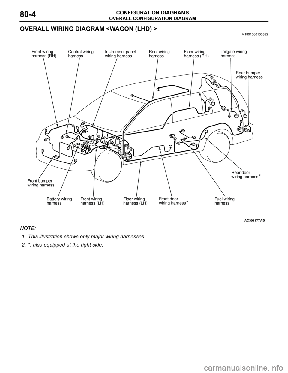
OVERALL CONFIGURATION DIAGRAM
CONFIGURATION DIAGRAMS80-4
OVERALL WIRING DIAGRAM
NOTE: .
1. This illustration shows only major wiring harnesses.
2. *: also equipped at the right side.
AC301177AB
Front wiring
harness (RH)Control wiring
harnessInstrument panel
wiring harnessRoof wiring
harnessFloor wiring
harness (RH)
Battery wiring
harnessFront wiring
harness (LH)Front door
wiring harness Floor wiring
harness (LH)Fuel wiring
harnessRear door
wiring harness
Front bumper
wiring harness
Rear bumper
wiring harness
**
Tailgate wiring
harness
Page 611 of 788
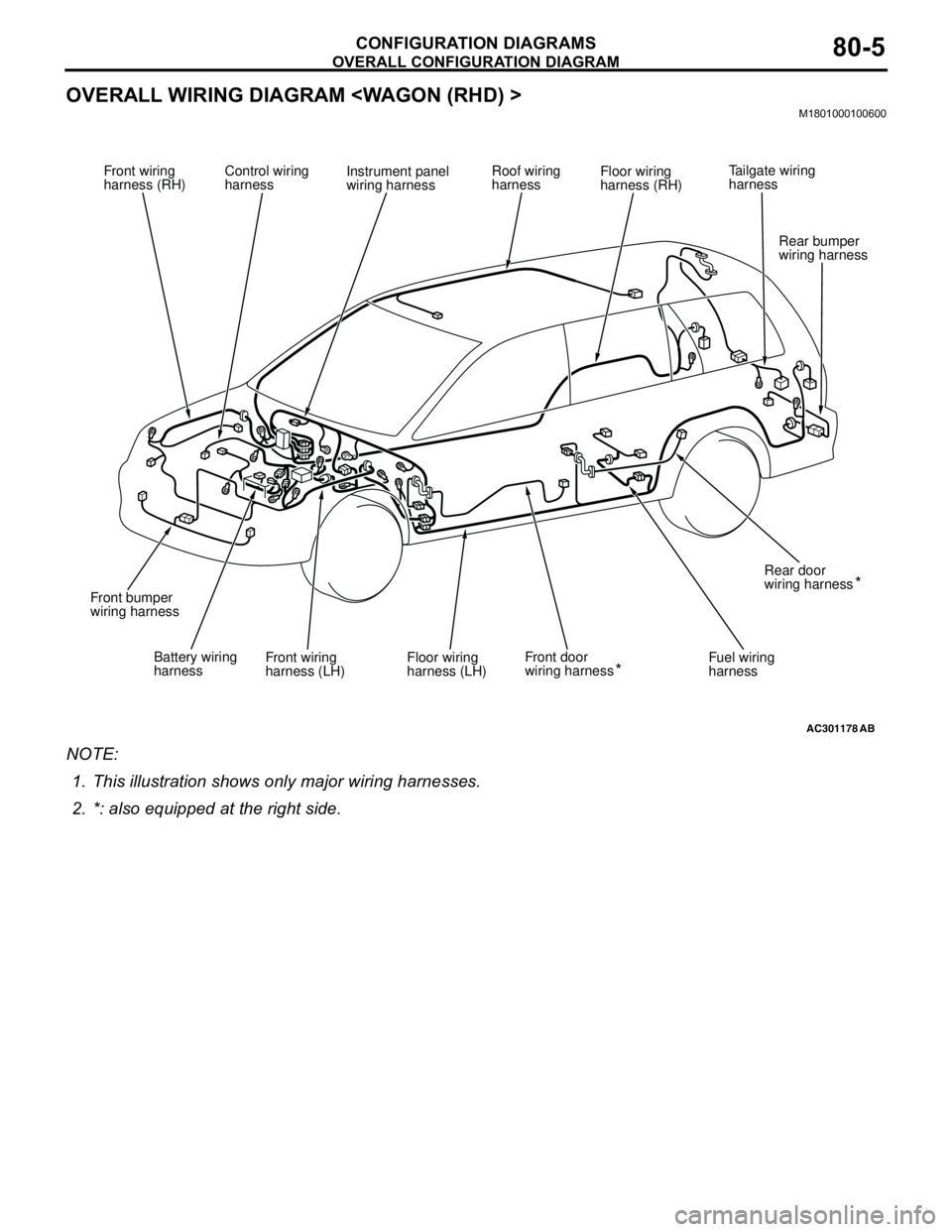
OVERALL CONFIGURATION DIAGRAM
CONFIGURATION DIAGRAMS80-5
OVERALL WIRING DIAGRAM
NOTE: .
1. This illustration shows only major wiring harnesses.
2. *: also equipped at the right side.
AC301178AB
Front wiring
harness (RH)Control wiring
harnessInstrument panel
wiring harnessRoof wiring
harnessFloor wiring
harness (RH)
Battery wiring
harnessFront wiring
harness (LH)Front door
wiring harness Floor wiring
harness (LH)Fuel wiring
harnessRear door
wiring harness
Front bumper
wiring harness
Rear bumper
wiring harness
**
Tailgate wiring
harness
Page 622 of 788
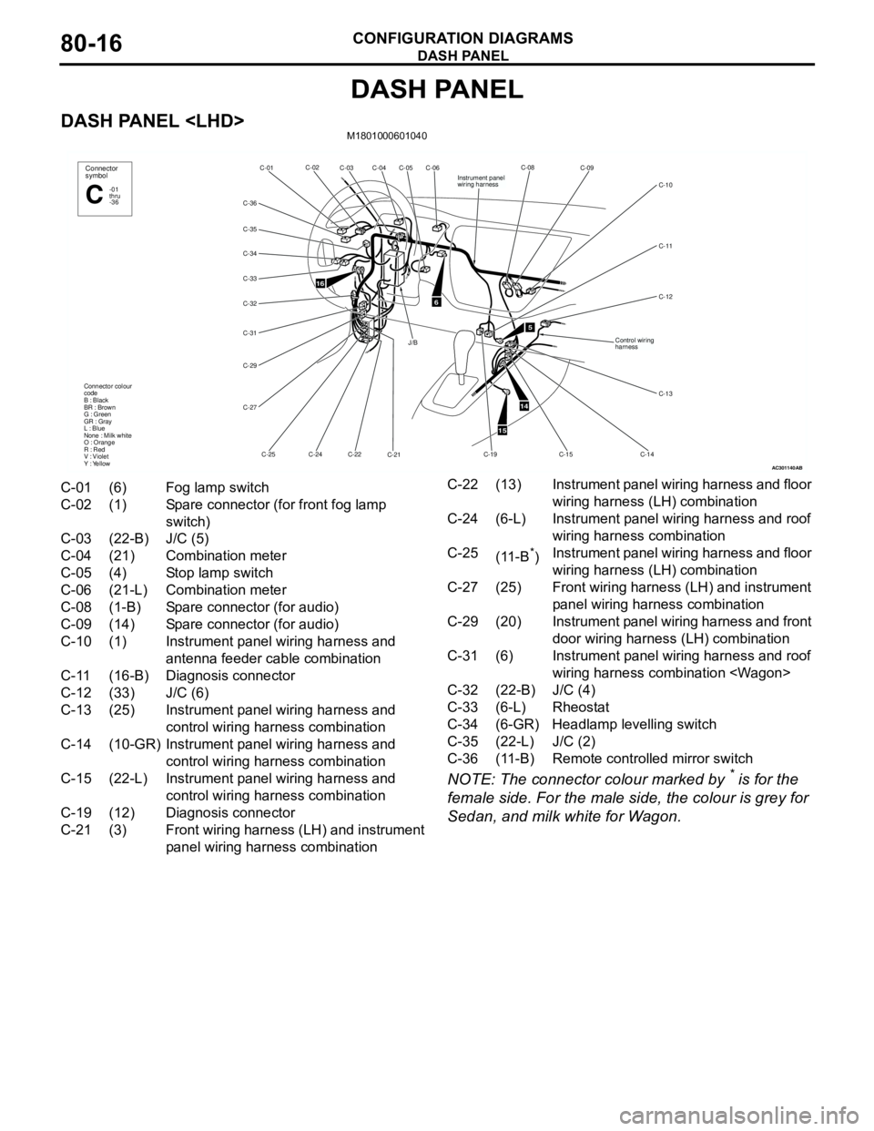
DASH PANEL
CONFIGURATION DIAGRAMS80-16
DASH PANEL
DASH PANEL
NOTE: The connector colour marked by * is for the
female side. For the male side, the colour is grey for
Sedan, and milk white for Wagon.
AC301140
16
C-06
C-05 C-02
C-01
C-34
C-32
C-31
C-29
C-27
C-25C-24C-22
C-21 Connector colour
code
B : Black
BR : Brown
G : Green
GR : Gray
L : Blue
None : Milk white
O : Orange
R : Red
V : Violet
Y : YellowConnector
symbol
-01
thru
-36C
C-04 C-03
C-36
C-33
C-35
6
J/B
AB
5
14
15
C-08
C-09
C-11
C-12 C-10
C-14
C-15
C-13
Instrument panel
wiring harness
Control wiring
harness
C-19
C-01 (6) Fog lamp switch
C-02 (1) Spare connector (for front fog lamp
switch)
C-03 (22-B) J/C (5)
C-04 (21) Combination meter
C-05 (4) Stop lamp switch
C-06 (21-L) Combination meter
C-08 (1-B) Spare connector (for audio)
C-09 (14) Spare connector (for audio)
C-10 (1) Instrument panel wiring harness and
antenna feeder cable combination
C-11 (16-B) Diagnosis connector
C-12 (33) J/C (6)
C-13 (25) Instrument panel wiring harness and
control wiring harness combination
C-14 (10-GR) Instrument panel wiring harness and
control wiring harness combination
C-15 (22-L) Instrument panel wiring harness and
control wiring harness combination
C-19 (12) Diagnosis connector
C-21 (3) Front wiring harness (LH) and instrument
panel wiring harness combinationC-22 (13) Instrument panel wiring harness and floor
wiring harness (LH) combination
C-24 (6-L) Instrument panel wiring harness and roof
wiring harness combination
C-25
(11-B
*)Instrument panel wiring harness and floor
wiring harness (LH) combination
C-27 (25) Front wiring harness (LH) and instrument
panel wiring harness combination
C-29 (20) Instrument panel wiring harness and front
door wiring harness (LH) combination
C-31 (6) Instrument panel wiring harness and roof
wiring harness combination
C-32 (22-B) J/C (4)
C-33 (6-L) Rheostat
C-34 (6-GR) Headlamp levelling switch
C-35 (22-L) J/C (2)
C-36 (11-B) Remote controlled mirror switch