instrument panel MITSUBISHI LANCER 2005 Workshop Manual
[x] Cancel search | Manufacturer: MITSUBISHI, Model Year: 2005, Model line: LANCER, Model: MITSUBISHI LANCER 2005Pages: 788, PDF Size: 45.98 MB
Page 255 of 788
STEERING SHAFT
POWER STEERING37-21
STEERING SHAFT
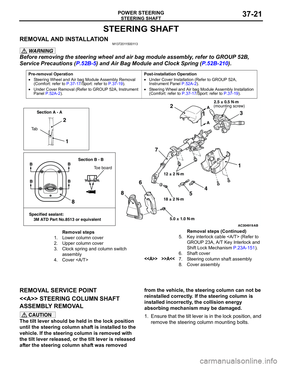
REMOVAL AND INSTALLATIONM1372011500113
WARNING
Before removing the steering wheel and air bag module assembly, refer to GROUP 52B,
Service Precautions (P.52B-5) and Air Bag Module and Clock Spring (P.52B-210).
REMOVAL SERVICE POINT
<> STEERING COLUMN SHAFT
ASSEMBLY REMOVAL
CAUTION
The tilt lever should be held in the lock position
until the steering column shaft is installed to the
vehicle. If the steering column is removed with
the tilt lever released, or the tilt lever is released
after the steering column shaft was removed from the vehicle, the steering column can not be
reinstalled correctly. If the steering column is
installed incorrectly, the collision energy
absorbing mechanism may be damaged.
1. Ensure that the tilt lever is in the lock position, and
remove the steering column mounting bolts.
Pre-removal Operation
•Steering Wheel and Air bag Module Assembly Removal
(Comfort: refer to P.37-17/Sport: refer to P.37-19).
•Under Cover Removal (Refer to GROUP 52A, Instrument
Panel P.52A-2).Post-installation Operation
•Under Cover Installation (Refer to GROUP 52A,
Instrument Panel P.52A-2).
•Steering Wheel and Air bag Module Assembly Installation
(Comfort: refer to P.37-17/Sport: refer to P.37-19).
AC304919AB
12 ± 2 N·m
18 ± 2 N·m
5.0 ± 1.0 N·m
1 2
73 2
1
8
86
A
A
Ta bSection A - A
Section B - B
BB
Toe board
Specified sealant:
3M ATD Part No.8513 or equivalent
BB
4
5
(mounting screw)2.5 ± 0.5 N·m
Removal steps
1. Lower column cover
2. Upper column cover
3. Clock spring and column switch
assembly
4. Cover 5. Key interlock cable (Refer to
GROUP 23A, A/T Key Interlock and
Shift Lock Mechanism P.23A-151).
6. Shaft cover
<> >>A<<7. Steering column shaft assembly
8. Cover assemblyRemoval steps (Continued)
Page 383 of 788
DOOR MIRROR
EXTERIOR51-45
DOOR MIRROR
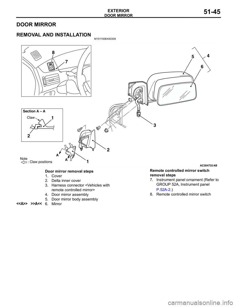
REMOVAL AND INSTALLATIONM1511006400308
AC304733
Note
: Claw positions
AB
A
A Section A – A
Claw1
2
1234
5
6 7 8
Door mirror removal steps
1. Cover
2. Delta inner cover
3. Harness connector
4. Door mirror assembly
5. Door mirror body assembly
<> >>A<<6. MirrorRemote controlled mirror switch
removal steps
7. Instrument panel ornament (Refer to
GROUP 52A, Instrument panel
P.52A-2.)
8. Remote controlled mirror switch
Page 417 of 788
COMBINATION METER ASSEMBLY
CHASSIS ELECTRICAL54A-29
COMBINATION METER ASSEMBLY
SERVICE SPECIFICATIONSM1543000300324
SEALANTM1543024600028
SPECIAL TOOLSM1543000601652
ItemStandard value
Speedometer indication error km/h (mph) 20 (12) 20 − 24 (12 − 15)
40 (25) 40 − 44 (25 − 28)
80 (50) 80 − 85 (50 − 53)
120 (75) 121 − 127 (75 − 79)
160 (100) 162 − 169 (100 − 105)
200 (125) 203 − 211 (126 − 131)
Tachometer indication error r/min 700
± 120
2,000
− 175 + 225
3,000
− 175 + 300
4,000
− 225 + 375
5,000
− 225 + 425
6,000
− 225 + 475
7,000
− 200 + 500
8,000
− 100 + 500
Fuel tank gauge unit resistance ΩFloat position F (highest) 3 ± 1
Float position E (lowest) 110 ± 1
Fuel gauge unit float height mm Float position F (A) 24.1 ± 2.0
Float position E (B) 151.6 ± 2.0
Engine coolant temperature gauge unit resistance Ω104 + 13.5 (at 70°C)
Item Specified sealant
Engine coolant temperature gauge unit 3M 1215 or equivalent
Tool Number Name Use
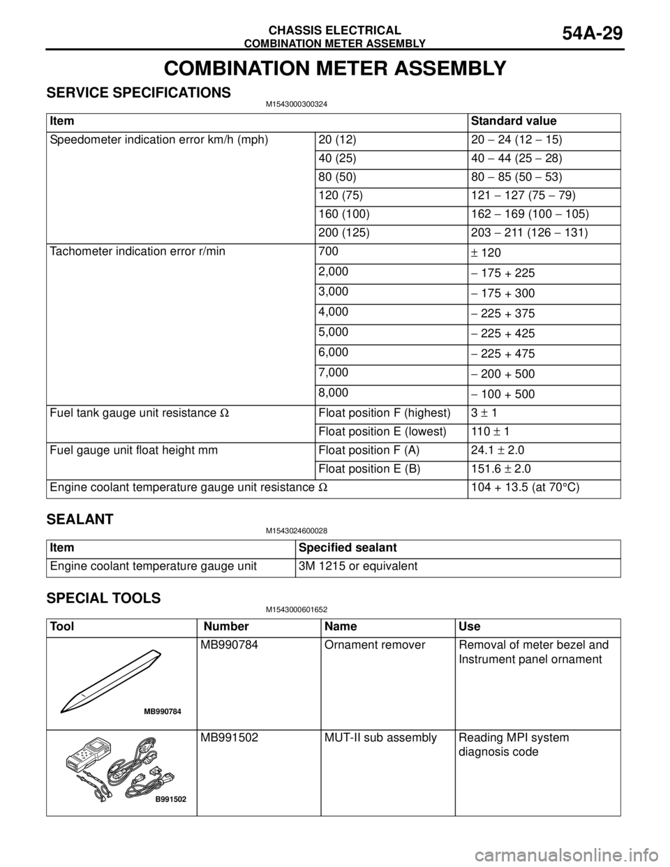
MB990784 Ornament remover Removal of meter bezel and
Instrument panel ornament
MB991502 MUT-II sub assembly Reading MPI system
diagnosis code
MB990784
B991502
Page 451 of 788
COMBINATION METER ASSEMBLY
CHASSIS ELECTRICAL54A-63
COMBINATION METER ASSEMBLY
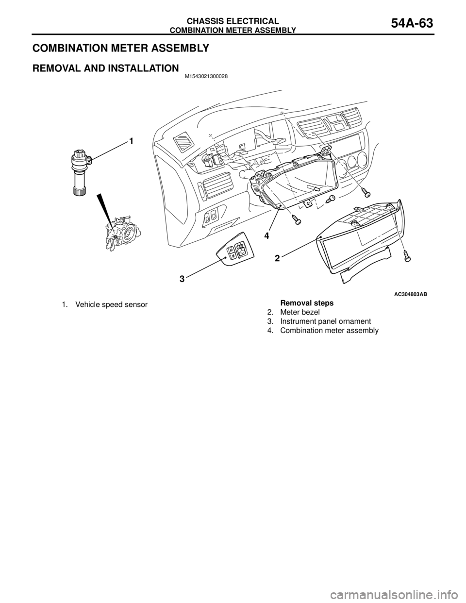
REMOVAL AND INSTALLATIONM1543021300028
AC304803
4
32
AB
1
1. Vehicle speed sensorRemoval steps
2. Meter bezel
3. Instrument panel ornament
4. Combination meter assembly
Page 459 of 788
FOG LAMP
CHASSIS ELECTRICAL54A-71
FOG LAMP
SERVICE SPECIFICATIONM1542000300343
SPECIAL TOOLM1542000600894
TROUBLESHOOTINGM1542000701292
When the front fog lamp switch is turned to ON with
the tail lamp or the headlamp on (the tail lamp switch
or the headlamp switch is ON), the fog lamp relay
turns on, and the fog lamps will illuminate.
If the tail lamps or the headlamps are turned off with
the lighting switch OFF while the fog lamps are on,
the front fog lamps turn off at the same time to
prevent unattended operation.
If the tail lamps are turned off by the headlamp
automatic shutdown function, the fog lamps turn off
at the same time. However, if the tail lamps illuminate
again, the fog lamps do not.
The front fog lamps are controlled by the Smart
Wiring System (SWS). For troubleshooting, refer to
respective Groups below.
•Not using SWS monitor: GROUP 54B, SWS
Troubleshooting P.54B-38.
•Using SWS monitor: GROUP 54C, SWS
Troubleshooting P.54C-22.
ON-VEHICLE SERVICE
FRONT FOG LAMP AIMING CHECKM1542001100438
After setting the vehicles to the following condition,
adjust the front fog lamp aiming.
•Check that the tyre inflation pressure is at the
value indicated on the tyre pressure labels.
•Set the vehicle to the unladen condition and park
it on a level surface.
•Have a single person (approximately 75 kg) sit in
the driver’s seat.•Run the engine at a speed of 2000 r/min to fully
charge the battery.
Turn on the front fog lamps and check that the
illumination is within the standard value range.
Standard value: Illuminates to within 40
metres
CAUTION
For the fog lamp which is not being measured,
disconnect that fog lamp’s connector if possible
so that it does not illuminate while carrying out
the adjustment. Furthermore, make sure that the
light axis does not get shifted when
re-connecting the connector.
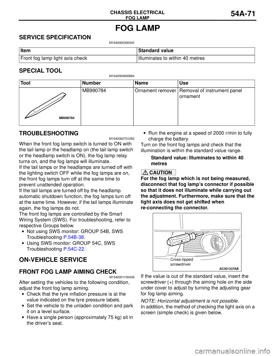
If the value is out of the standard value, insert the
screwdriver (+) through the aiming hole on the side
under cover to adjust by turning the adjusting gear
for fog lamp aiming.
NOTE: Horizontal adjustment is not possible.
In addition, the method of checking the light axis on a
screen (simple check) is given below. Item Standard value
Front fog lamp light axis check Illuminates to within 40 metres
Tool Number Name Use
MB990784 Ornament remover Removal of instrument panel
ornament
MB990784
AC301337
Cross-tipped
screwdriver
AB
Page 462 of 788
FOG LAMP
CHASSIS ELECTRICAL54A-74
FOG LAMP SWITCH
REMOVAL AND INSTALLATIONM1542013900033
INSPECTIONM1542011200919
FRONT FOG LAMP SWITCH CONTINUITY
CHECK
AC304663AB
21
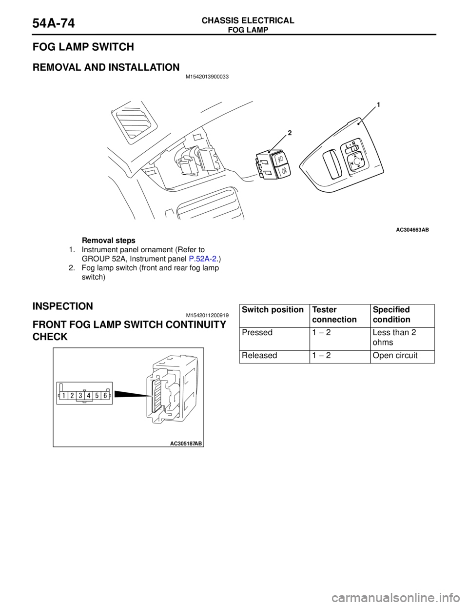
Removal steps
1. Instrument panel ornament (Refer to
GROUP 52A, Instrument panel P.52A-2.)
2. Fog lamp switch (front and rear fog lamp
switch)
AC305187
AB
Switch position Tester
connectionSpecified
condition
Pressed 1 − 2 Less than 2
ohms
Released 1 − 2 Open circuit
Page 463 of 788
REAR FOG LAMP
CHASSIS ELECTRICAL54A-75
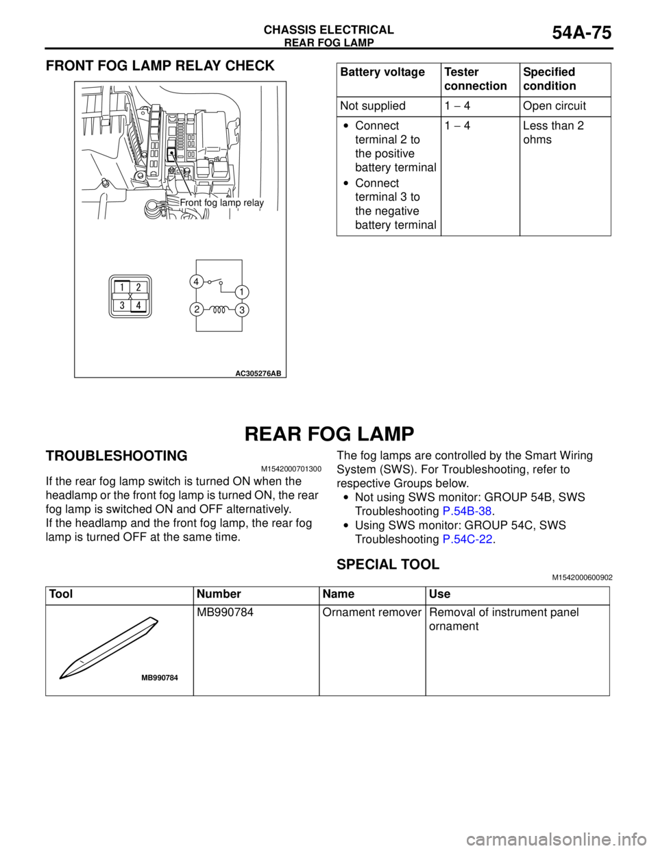
FRONT FOG LAMP RELAY CHECK
REAR FOG LAMP
TROUBLESHOOTINGM1542000701300
If the rear fog lamp switch is turned ON when the
headlamp or the front fog lamp is turned ON, the rear
fog lamp is switched ON and OFF alternatively.
If the headlamp and the front fog lamp, the rear fog
lamp is turned OFF at the same time.The fog lamps are controlled by the Smart Wiring
System (SWS). For Troubleshooting, refer to
respective Groups below.
•Not using SWS monitor: GROUP 54B, SWS
Troubleshooting P.54B-38.
•Using SWS monitor: GROUP 54C, SWS
Troubleshooting P.54C-22.
SPECIAL TOOLM1542000600902
1 4
3 2
AC305276
AB
Front fog lamp relay
Battery voltage Tester
connectionSpecified
condition
Not supplied 1 − 4 Open circuit
•Connect
terminal 2 to
the positive
battery terminal
•Connect
terminal 3 to
the negative
battery terminal1 − 4 Less than 2
ohms
Tool Number Name Use
MB990784 Ornament remover Removal of instrument panel
ornament
MB990784
Page 482 of 788
ANTENNA
CHASSIS ELECTRICAL54A-94
ANTENNA
REMOVAL AND INSTALLATIONM1544002900529
Pre-removal and Post-installation Operation
•Front pillar trim, Rear pillar trim, Centre pillar trim lower,
Centre pillar trim upper (Refer to GROUP 52A − Trims
P.52A-11.)
•Headlining Removal and Installation (Refer to GROUP
52A, Headlining P.52A-21.)
AC305315AB
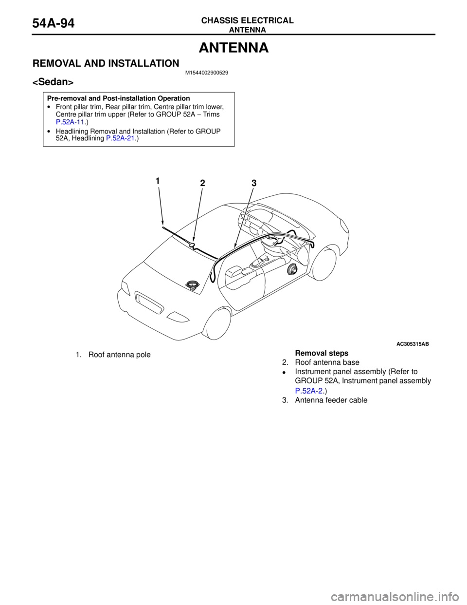
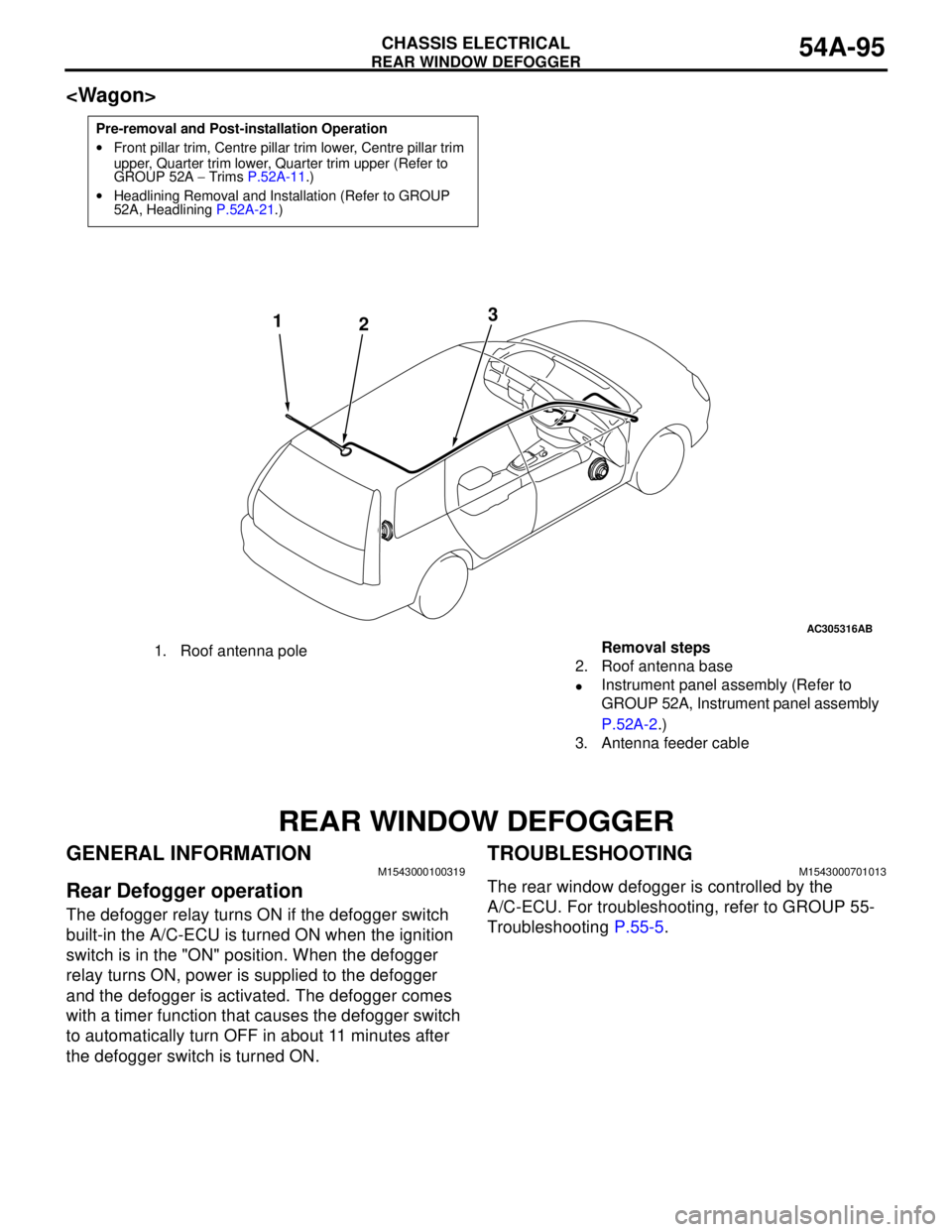
1
23
1. Roof antenna poleRemoval steps
2. Roof antenna base
•Instrument panel assembly (Refer to
GROUP 52A, Instrument panel assembly
P.52A-2.)
3. Antenna feeder cable
Page 483 of 788
REAR WINDOW DEFOGGER
CHASSIS ELECTRICAL54A-95
REAR WINDOW DEFOGGER
GENERAL INFORMATIONM1543000100319
Rear Defogger operation
The defogger relay turns ON if the defogger switch
built-in the A/C-ECU is turned ON when the ignition
switch is in the "ON" position. When the defogger
relay turns ON, power is supplied to the defogger
and the defogger is activated. The defogger comes
with a timer function that causes the defogger switch
to automatically turn OFF in about 11 minutes after
the defogger switch is turned ON.
TROUBLESHOOTINGM1543000701013
The rear window defogger is controlled by the
A/C-ECU. For troubleshooting, refer to GROUP 55-
Troubleshooting P.55-5.
Pre-removal and Post-installation Operation
•Front pillar trim, Centre pillar trim lower, Centre pillar trim
upper, Quarter trim lower, Quarter trim upper (Refer to
GROUP 52A − Trims P.52A-11.)
•Headlining Removal and Installation (Refer to GROUP
52A, Headlining P.52A-21.)
AC305316
AB
1
23
1. Roof antenna poleRemoval steps
2. Roof antenna base
•Instrument panel assembly (Refer to
GROUP 52A, Instrument panel assembly
P.52A-2.)
3. Antenna feeder cable
Page 560 of 788
ON-VEHICLE SERVICE
HEATER, AIR CONDITIONER AND VENTILATION55-76
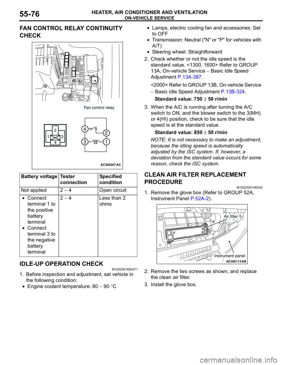
FAN CONTROL RELAY CONTINUITY
CHECK
IDLE-UP OPERATION CHECK
M1552001600371
1. Before inspection and adjustment, set vehicle in
the following condition:
•Engine coolant temperature: 80 − 90 °C•Lamps, electric cooling fan and accessories: Set
to OFF
•Transmission: Neutral ("N" or "P" for vehicles with
A/T)
•Steering wheel: Straightforward
2. Check whether or not the idle speed is the
standard value. <1300, 1600> Refer to GROUP
13A, On-vehicle Service − Basic Idle Speed
Adjustment P.13A-387.
<2000> Refer to GROUP 13B, On-vehicle Service
− Basic Idle Speed Adjustment P.13B-324.
Standard value: 750 ± 50 r/min
3. When the A/C is running after turning the A/C
switch to ON, and the blower switch to the 3(MH)
or 4(HI) position, check to be sure that the idle
speed is at the standard value.
Standard value: 850 ± 50 r/min
NOTE: It is not necessary to make an adjustment,
because the idling speed is automatically
adjusted by the ISC system. If, however, a
deviation from the standard value occurs for some
reason, check the ISC system.
CLEAN AIR FILTER REPLACEMENT
PROCEDURE
M1552020100030
1. Remove the glove box (Refer to GROUP 52A,
Instrument Panel P.52A-2).
2. Remove the two screws as shown, and replace
the clean air filter.
3. Install the glove box. Battery voltage Tester
connectionSpecified
condition
Not applied 2 − 4 Open circuit
•Connect
terminal 1 to
the positive
battery
terminal
•Connect
terminal 3 to
the negative
battery
terminal2 − 4 Less than 2
ohms
AC305307
Fan control relay
13
4 2
3 4
1 2
AC
AC305114AB
Air filter
Instrument panel