coil MITSUBISHI LANCER 2005 Owner's Guide
[x] Cancel search | Manufacturer: MITSUBISHI, Model Year: 2005, Model line: LANCER, Model: MITSUBISHI LANCER 2005Pages: 788, PDF Size: 45.98 MB
Page 217 of 788
SHOCK ABSORBER ASSEMBLY
REAR SUSPENSION34-17
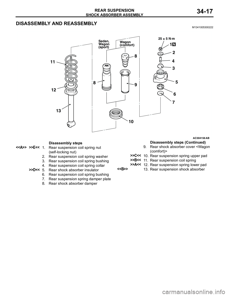
DISASSEMBLY AND REASSEMBLYM1341005300222
AC304156
AB
25 ± 5 N·m
1
2
4
5 3
6
7 8
9 11
13 12
10
8
Wagon
(comfort) Sedan,
Wagon
(sport)
Disassembly steps
<> >>E<<1. Rear suspension coil spring nut
(self-locking nut)
2. Rear suspension coil spring washer
3. Rear suspension coil spring bushing
4. Rear suspension coil spring collar
>>D<<5. Rear shock absorber insulator
6. Rear suspension coil spring bushing
7. Rear suspension spring damper plate
8. Rear shock absorber damper9. Rear shock absorber cover
>>C<<10. Rear suspension spring upper pad
>>B<<11. Rear suspension coil spring
>>A<<12. Rear suspension spring lower pad
<>13. Rear suspension shock absorberDisassembly steps (Continued)
Page 218 of 788
Page 219 of 788
SHOCK ABSORBER ASSEMBLY
REAR SUSPENSION34-19
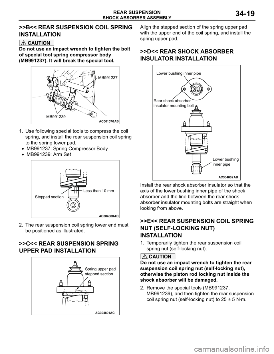
>>B<< REAR SUSPENSION COIL SPRING
INSTALLATION
CAUTION
Do not use an impact wrench to tighten the bolt
of special tool spring compressor body
(MB991237). It will break the special tool.
1. Use following special tools to compress the coil
spring, and install the rear suspension coil spring
to the spring lower pad.
•MB991237: Spring Compressor Body
•MB991239: Arm Set
2. The rear suspension coil spring lower end must
be positioned as illustrated.
>>C<< REAR SUSPENSION SPRING
UPPER PAD INSTALLATION
Align the stepped section of the spring upper pad
with the upper end of the coil spring, and install the
spring upper pad.
>>D<< REAR SHOCK ABSORBER
INSULATOR INSTALLATION
Install the rear shock absorber insulator so that the
axis of the lower bushing inner pipe of the shock
absorber and the line between the rear shock
absorber insulator mounting bolts are straight when
looking from above.
>>E<< REAR SUSPENSION COIL SPRING
NUT (SELF-LOCKING NUT)
INSTALLATION
1. Temporarily tighten the rear suspension coil
spring nut (self-locking nut).
CAUTION
Do not use an impact wrench to tighten the rear
suspension coil spring nut (self-locking nut),
otherwise the piston rod locking nut inside the
shock absorber will be damaged.
2. Remove the special tools (MB991237,
MB991239), and then tighten the rear suspension
coil spring nut (self-locking nut) to 25 ± 5 N⋅m.
AC001070
MB991237
MB991239
AB
AC304800AC
Less than 10 mm
Stepped section
AC304801AC
Spring upper pad
stepped section
AC304802
Lower bushing inner pipe
Rear shock absorber
insulator mounting bolt
AB
Lower bushing
inner pipe
Page 247 of 788
ON-VEHICLE SERVICE
POWER STEERING37-13
STEERING WHEEL RETURN TO CENTRE
CHECK
M1372001800317
Conduct a road test:
1. Make both gradual and sudden turns and check
the steering wheel return.
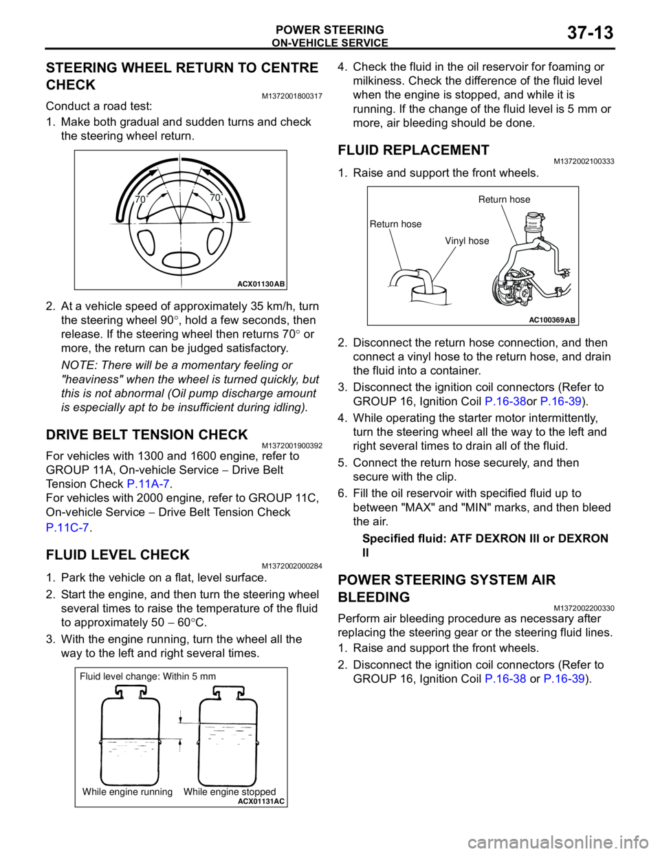
2. At a vehicle speed of approximately 35 km/h, turn
the steering wheel 90°, hold a few seconds, then
release. If the steering wheel then returns 70° or
more, the return can be judged satisfactory.
NOTE: There will be a momentary feeling or
"heaviness" when the wheel is turned quickly, but
this is not abnormal (Oil pump discharge amount
is especially apt to be insufficient during idling).
DRIVE BELT TENSION CHECKM1372001900392
For vehicles with 1300 and 1600 engine, refer to
GROUP 11A, On-vehicle Service − Drive Belt
Tension Check P.11A-7.
For vehicles with 2000 engine, refer to GROUP 11C,
On-vehicle Service − Drive Belt Tension Check
P.11C-7.
FLUID LEVEL CHECKM1372002000284
1. Park the vehicle on a flat, level surface.
2. Start the engine, and then turn the steering wheel
several times to raise the temperature of the fluid
to approximately 50 − 60°C.
3. With the engine running, turn the wheel all the
way to the left and right several times.4. Check the fluid in the oil reservoir for foaming or
milkiness. Check the difference of the fluid level
when the engine is stopped, and while it is
running. If the change of the fluid level is 5 mm or
more, air bleeding should be done.
FLUID REPLACEMENTM1372002100333
1. Raise and support the front wheels.
2. Disconnect the return hose connection, and then
connect a vinyl hose to the return hose, and drain
the fluid into a container.
3. Disconnect the ignition coil connectors (Refer to
GROUP 16, Ignition Coil P.16-38or P.16-39).
4. While operating the starter motor intermittently,
turn the steering wheel all the way to the left and
right several times to drain all of the fluid.
5. Connect the return hose securely, and then
secure with the clip.
6. Fill the oil reservoir with specified fluid up to
between "MAX" and "MIN" marks, and then bleed
the air.
Specified fluid: ATF DEXRON III or DEXRON
II
POWER STEERING SYSTEM AIR
BLEEDING
M1372002200330
Perform air bleeding procedure as necessary after
replacing the steering gear or the steering fluid lines.
1. Raise and support the front wheels.
2. Disconnect the ignition coil connectors (Refer to
GROUP 16, Ignition Coil P.16-38 or P.16-39).
ACX01130
AB
70˚70˚
ACX01131While engine running While engine stoppedAC
Fluid level change: Within 5 mm
AC100369AB
Return hoseReturn hose
Vinyl hose
Page 248 of 788
ON-VEHICLE SERVICE
POWER STEERING37-14
CAUTION
Perform air bleeding only while cranking the
engine. If air bleeding is performed while the
engine is running, air could enter the fluid.
During air bleeding, refill the steering fluid
supply so that the level never falls below the
"MIN" mark on the oil reservoir.
3. Turn the steering wheel all the way to the left and
right five or six times while using the starter motor
to crank the engine intermittently several times
(for 15 to 20 seconds).
4. Connect the ignition coil connectors (Refer to
GROUP 16, Ignition Coil P.16-38 or P.16-39).
5. Start the engine (idling).
6. Turn the steering wheel to the left and right until
there are no air bubbles in the oil reservoir.
7. Confirm that the fluid is not milky, and that the
level is between "MAX" and "MIN" marks.
8. Confirm that there is very little change in the fluid
level when the steering wheel is turned left and
right.
CAUTION
If the fluid level rises suddenly after the engine is
stopped, the air has not been completely bled. If
air bleeding is not complete, there will be
abnormal noises from the pump and the
flow-control valve, and this condition could
cause reduce the life of the power steering
components.
9. Confirm that the change in the fluid level is no
more than 5 mm when the engine is stopped and
when it is running.
10.If the change of the fluid level is 5 mm or more,
the air has not been completely bled from the
system. The air bleeding procedure must be
repeated.
OIL PUMP PRESSURE TESTM1372002300315
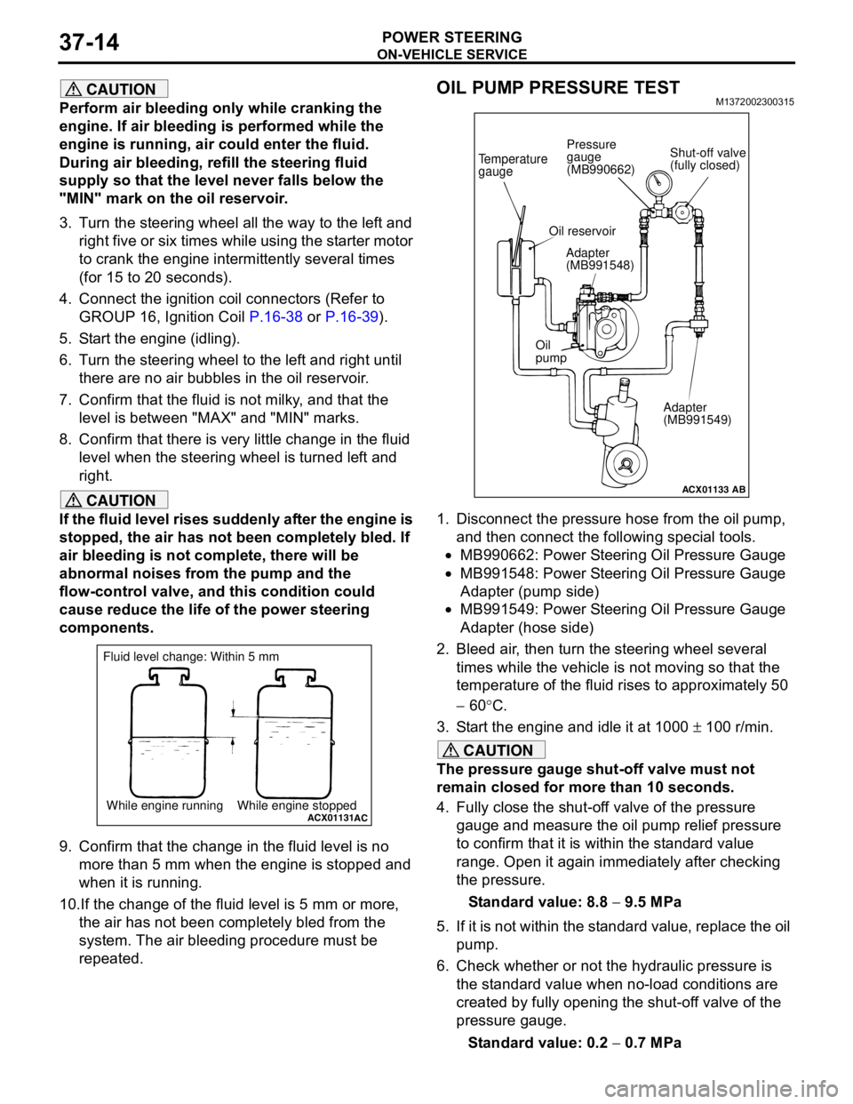
1. Disconnect the pressure hose from the oil pump,
and then connect the following special tools.
•MB990662: Power Steering Oil Pressure Gauge
•MB991548: Power Steering Oil Pressure Gauge
Adapter (pump side)
•MB991549: Power Steering Oil Pressure Gauge
Adapter (hose side)
2. Bleed air, then turn the steering wheel several
times while the vehicle is not moving so that the
temperature of the fluid rises to approximately 50
− 60°C.
3. Start the engine and idle it at 1000 ± 100 r/min.
CAUTION
The pressure gauge shut-off valve must not
remain closed for more than 10 seconds.
4. Fully close the shut-off valve of the pressure
gauge and measure the oil pump relief pressure
to confirm that it is within the standard value
range. Open it again immediately after checking
the pressure.
Standard value: 8.8 − 9.5 MPa
5. If it is not within the standard value, replace the oil
pump.
6. Check whether or not the hydraulic pressure is
the standard value when no-load conditions are
created by fully opening the shut-off valve of the
pressure gauge.
Standard value: 0.2 − 0.7 MPa
ACX01131While engine running While engine stoppedAC
Fluid level change: Within 5 mm
ACX01133
Temperature
gauge
Oil reservoir
Adapter
(MB991548)
Oil
pump
Adapter
(MB991549)
AB
Shut-off valve
(fully closed) Pressure
gauge
(MB990662)
Page 558 of 788
ON-VEHICLE SERVICE
HEATER, AIR CONDITIONER AND VENTILATION55-74
REFRIGERANT LEAK REPAIR
PROCEDURE
M1552001500277
LOST CHARGE
If the system has lost all charge due to a leak:
1. Evacuate the system (Refer to P.55-72).
2. Charge the system with approximately 480 − 520
g of refrigerant.
3. Check for leaks.
4. Discharge the system.
5. Repair leaks.
CAUTION
Replacement filter-drier units must be sealed
while in storage. The drier used in these units will
saturate water quickly upon exposure to the
atmosphere. When installing a drier, have all
tools and supplies ready for quick assembly to
avoid keeping the system open any longer than
necessary.
6. Replace receiver drier.
7. Evacuate and charge system.
LOW CHARGE
If the system has not lost all of its refrigerant charge;
locate and repair all leaks. If it is necessary to
increase the system pressure to find the leak
(because of an especially low charge) add
refrigerant. If it is possible to repair the leak without
discharging the refrigerant system, use the
procedure for correcting low refrigerant level.
HANDLING TUBING AND FITTINGS
Kinks in the refrigerant tubing or sharp bends in the
refrigerant hose lines will greatly reduce the capacity
of the entire system. High pressures are produced in
the system when it is operating. Extreme care must
be exercised to make sure that all connections are
pressure tight. Dirt and moisture can enter the
system when it is opened for repair or replacement of
lines or components. The following precautions must
be observed. The system must be completely
discharged before opening any fitting of connection
in the refrigeration system. Open fittings with caution
even after the system has been discharged. If any
pressure is noticed as a fitting is loosened, allow
trapped pressure to bleed off very slowly.
Never attempt to rebend formed lines to fit. Use the
correct line for the installation you are servicing. A
good rule for the flexible hose lines is keep the radius
of all bends at least 10 times the diameter of the
hose.Sharper bends will reduce the flow of refrigerant. The
flexible hose lines should be routed so that they are
at least 80 mm from the exhaust manifold. It is good
practice to inspect all flexible hose lines at least once
a year to make sure they are in good condition and
properly routed.
On standard plumbing fittings with O-rings, these
O-rings are not reusable.
COMPRESSOR NOISE CHECKM1552008700272
You must first know the conditions when the noise
occurs. These conditions are: weather, vehicle
speed, in gear or neutral, engine temperature or any
other special conditions.
Noises that develop during A/C operation can often
be misleading. For example: what sounds like a
failed front bearing or connecting rod, may be
caused by loose bolts, nuts, mounting brackets, or a
loose clutch assembly. Verify accessory drive belt
tension (power steering or alternator).
Improper accessory drive belt tension can cause a
misleading noise when the compressor is engaged
and little or no noise when the compressor is
disengaged.
Drive belts are speed-sensitive. That is, at different
engine speeds, and depending upon belt tension,
belts can develop unusual noises that are often
mistaken for mechanical problems within the
compressor.
ADJUSTMENT
1. Select a quiet area for testing. Duplicate
conditions as much as possible. Switch the
compressor on and off several times to clearly
identify compressor noise. To duplicate high
ambient conditions (high head pressure), restrict
air flow through the condenser. Install a manifold
gauge set to make sure discharge pressure
doesn't exceed 2,070 kPa.
2. Tighten all compressor mounting bolts, clutch
mounting bolt, and compressor drive belt. Check
to assure clutch coil is tight (no rotation or
wobble).
3. Check refrigerant hoses for rubbing or
interference that can cause unusual noises.
4. Check refrigerant charge (Refer to P.55-69).
5. Recheck compressor noise as in Step 1.
6. If noise still exists, loosen compressor mounting
bolts and retighten. Repeat Step 1.
7. If noise continues, replace compressor and repeat
Step 1.
Page 579 of 788
COMPRESSOR ASSEMBLY AND TENSION PULLEY
HEATER, AIR CONDITIONER AND VENTILATION55-95
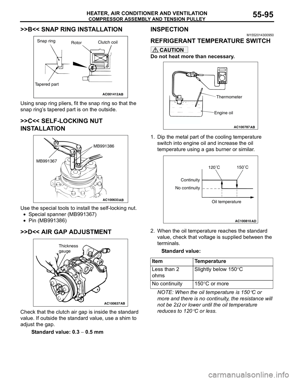
>>B<< SNAP RING INSTALLATION
Using snap ring pliers, fit the snap ring so that the
snap ring’s tapered part is on the outside.
>>C<< SELF-LOCKING NUT
INSTALLATION
Use the special tools to install the self-locking nut.
•Special spanner (MB991367)
•Pin (MB991386)
>>D<< AIR GAP ADJUSTMENT
Check that the clutch air gap is inside the standard
value. If outside the standard value, use a shim to
adjust the gap.
Standard value: 0.3 − 0.5 mm
INSPECTIONM1552014300950
REFRIGERANT TEMPERATURE SWITCH
CAUTION
Do not heat more than necessary.
1. Dip the metal part of the cooling temperature
switch into engine oil and increase the oil
temperature using a gas burner or similar.
2. When the oil temperature reaches the standard
value, check that voltage is supplied between the
terminals.
Standard value:
NOTE: When the oil temperature is 150
°C or
more and there is no continuity, the resistance will
not be 2
Ω or lower until the oil temperature
reduces to 120
°C or less.
AC001412
Snap ring
RotorClutch coil
Tapered part
AB
AC100633AB
MB991386
MB991367
AC100637AB
Thickness
gauge
Item Temperature
Less than 2
ohmsSlightly below 150°C
No continuity 150°C or more
AC100787
Thermometer
Engine oil
AB
AC100810
Continuity
No continuity
Oil temperature
AD
120˚C150˚C
Page 591 of 788
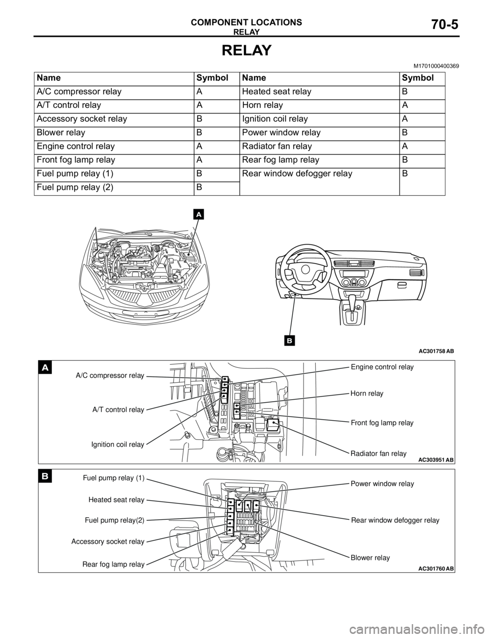
RELAY
COMPONENT LOCATIONS70-5
RELAY
M1701000400369
Name Symbol Name Symbol
A/C compressor relay A Heated seat relay B
A/T control relay A Horn relay A
Accessory socket relay B Ignition coil relay A
Blower relay B Power window relay B
Engine control relay A Radiator fan relay A
Front fog lamp relay A Rear fog lamp relay B
Fuel pump relay (1) B Rear window defogger relay B
Fuel pump relay (2) B
AC301758AB
A
B
AC303951AB
A/C compressor relayEngine control relay
Horn relay
Front fog lamp relay
Radiator fan relay A/T control relay
Ignition coil relayA
AC301760
Fuel pump relay (1)
Power window relay
Rear window defogger relay
Blower relay Heated seat relay
Fuel pump relay(2)
Accessory socket relay
Rear fog lamp relayAB
B
Page 593 of 788
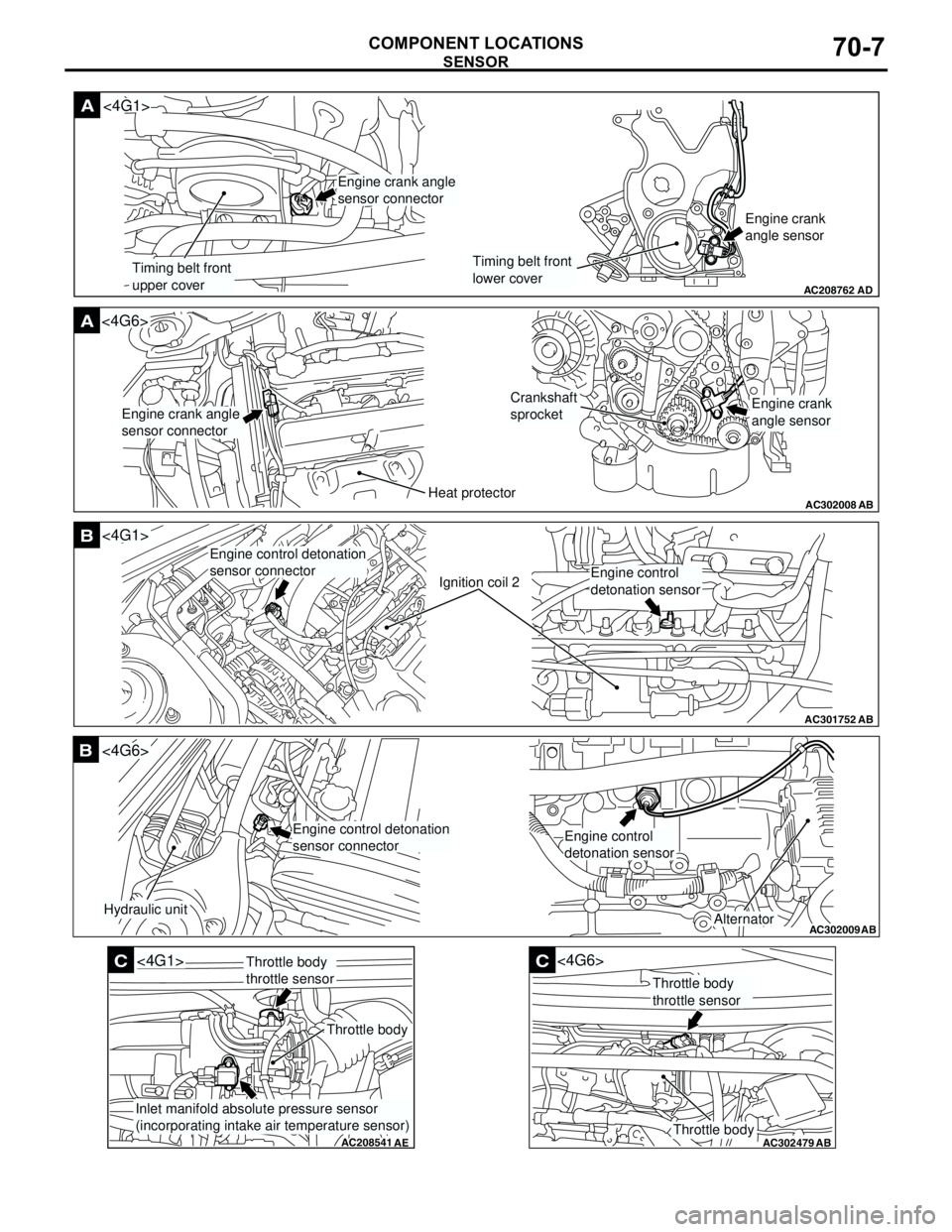
SENSOR
COMPONENT LOCATIONS70-7
AC208762
A
AD
Timing belt front
upper coverTiming belt front
lower coverEngine crank
angle sensor
<4G1>
Engine crank angle
sensor connector
AC302008
A<4G6>
ABHeat protector
Crankshaft
sprocket
Engine crank angle
sensor connectorEngine crank
angle sensor
AC301752
B
AB
Ignition coil 2
<4G1>
Engine control detonation
sensor connector
Engine control
detonation sensor
AC302009
B
AB
Hydraulic unit
<4G6>
Alternator
Engine control detonation
sensor connectorEngine control
detonation sensor
AC208541
C
AE
<4G1>
Throttle body
Throttle body
throttle sensor
Inlet manifold absolute pressure sensor
(incorporating intake air temperature sensor)
AC302479
AB
C
Throttle body
<4G6>
Throttle body
throttle sensor
Page 595 of 788