key MITSUBISHI LANCER 2005 Workshop Manual
[x] Cancel search | Manufacturer: MITSUBISHI, Model Year: 2005, Model line: LANCER, Model: MITSUBISHI LANCER 2005Pages: 788, PDF Size: 45.98 MB
Page 178 of 788
CROSSMEMBER
POWER PLANT MOUNT32-8
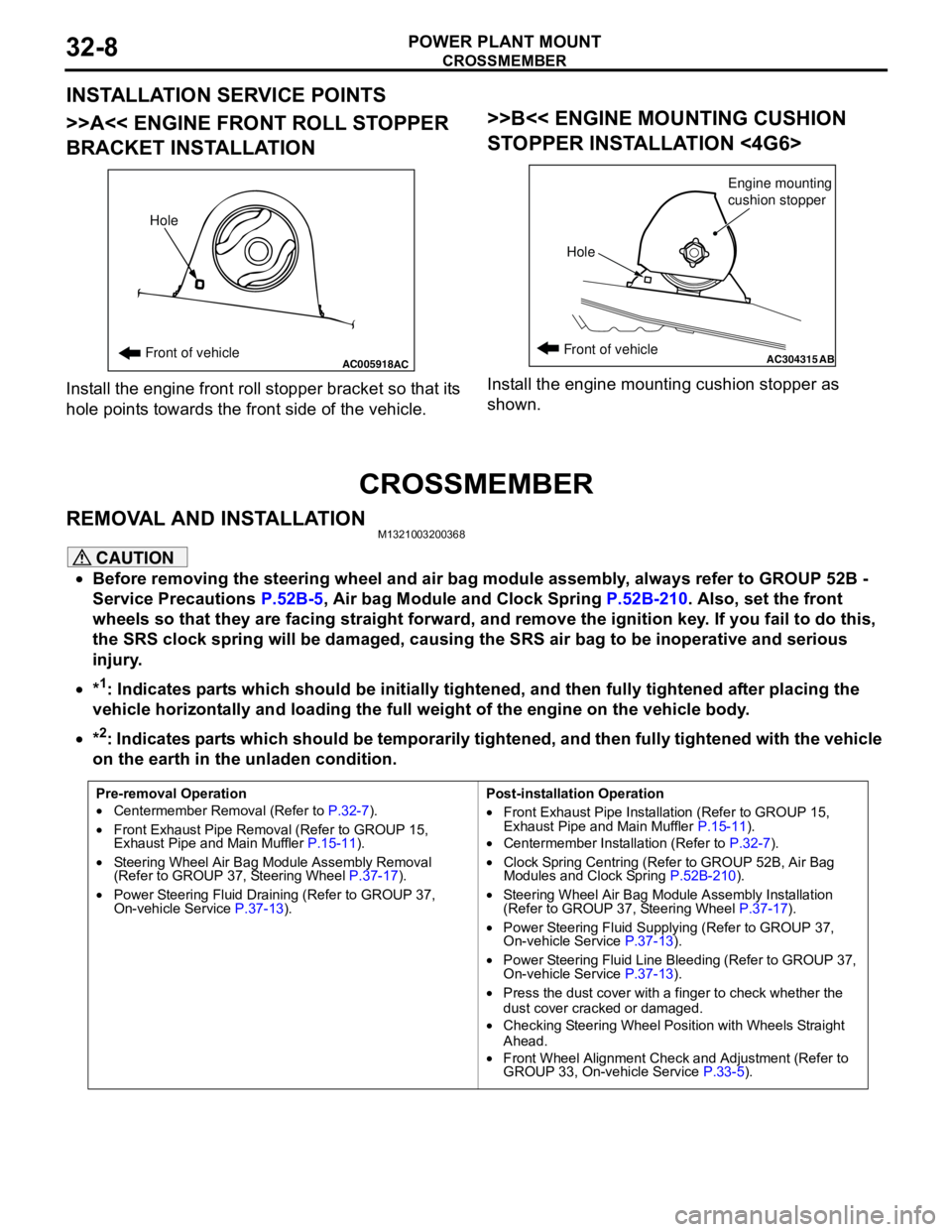
INSTALLATION SERVICE POINTS
>>A<< ENGINE FRONT ROLL STOPPER
BRACKET INSTALLATION
Install the engine front roll stopper bracket so that its
hole points towards the front side of the vehicle.
>>B<< ENGINE MOUNTING CUSHION
STOPPER INSTALLATION <4G6>
Install the engine mounting cushion stopper as
shown.
CROSSMEMBER
REMOVAL AND INSTALLATIONM1321003200368
CAUTION
•Before removing the steering wheel and air bag module assembly, always refer to GROUP 52B -
Service Precautions P.52B-5, Air bag Module and Clock Spring P.52B-210. Also, set the front
wheels so that they are facing straight forward, and remove the ignition key. If you fail to do this,
the SRS clock spring will be damaged, causing the SRS air bag to be inoperative and serious
injury.
•*
1: Indicates parts which should be initially tightened, and then fully tightened after placing the
vehicle horizontally and loading the full weight of the engine on the vehicle body.
•*
2: Indicates parts which should be temporarily tightened, and then fully tightened with the vehicle
on the earth in the unladen condition.
AC005918Front of vehicleHoleACAC304315ABFront of vehicle
HoleEngine mounting
cushion stopper
Pre-removal Operation
•Centermember Removal (Refer to P.32-7).
•Front Exhaust Pipe Removal (Refer to GROUP 15,
Exhaust Pipe and Main Muffler P.15-11).
•Steering Wheel Air Bag Module Assembly Removal
(Refer to GROUP 37, Steering Wheel P.37-17).
•Power Steering Fluid Draining (Refer to GROUP 37,
On-vehicle Service P.37-13).Post-installation Operation
•Front Exhaust Pipe Installation (Refer to GROUP 15,
Exhaust Pipe and Main Muffler P.15-11).
•Centermember Installation (Refer to P.32-7).
•Clock Spring Centring (Refer to GROUP 52B, Air Bag
Modules and Clock Spring P.52B-210).
•Steering Wheel Air Bag Module Assembly Installation
(Refer to GROUP 37, Steering Wheel P.37-17).
•Power Steering Fluid Supplying (Refer to GROUP 37,
On-vehicle Service P.37-13).
•Power Steering Fluid Line Bleeding (Refer to GROUP 37,
On-vehicle Service P.37-13).
•Press the dust cover with a finger to check whether the
dust cover cracked or damaged.
•Checking Steering Wheel Position with Wheels Straight
Ahead.
•Front Wheel Alignment Check and Adjustment (Refer to
GROUP 33, On-vehicle Service P.33-5).
Page 255 of 788
STEERING SHAFT
POWER STEERING37-21
STEERING SHAFT
REMOVAL AND INSTALLATIONM1372011500113
WARNING
Before removing the steering wheel and air bag module assembly, refer to GROUP 52B,
Service Precautions (P.52B-5) and Air Bag Module and Clock Spring (P.52B-210).
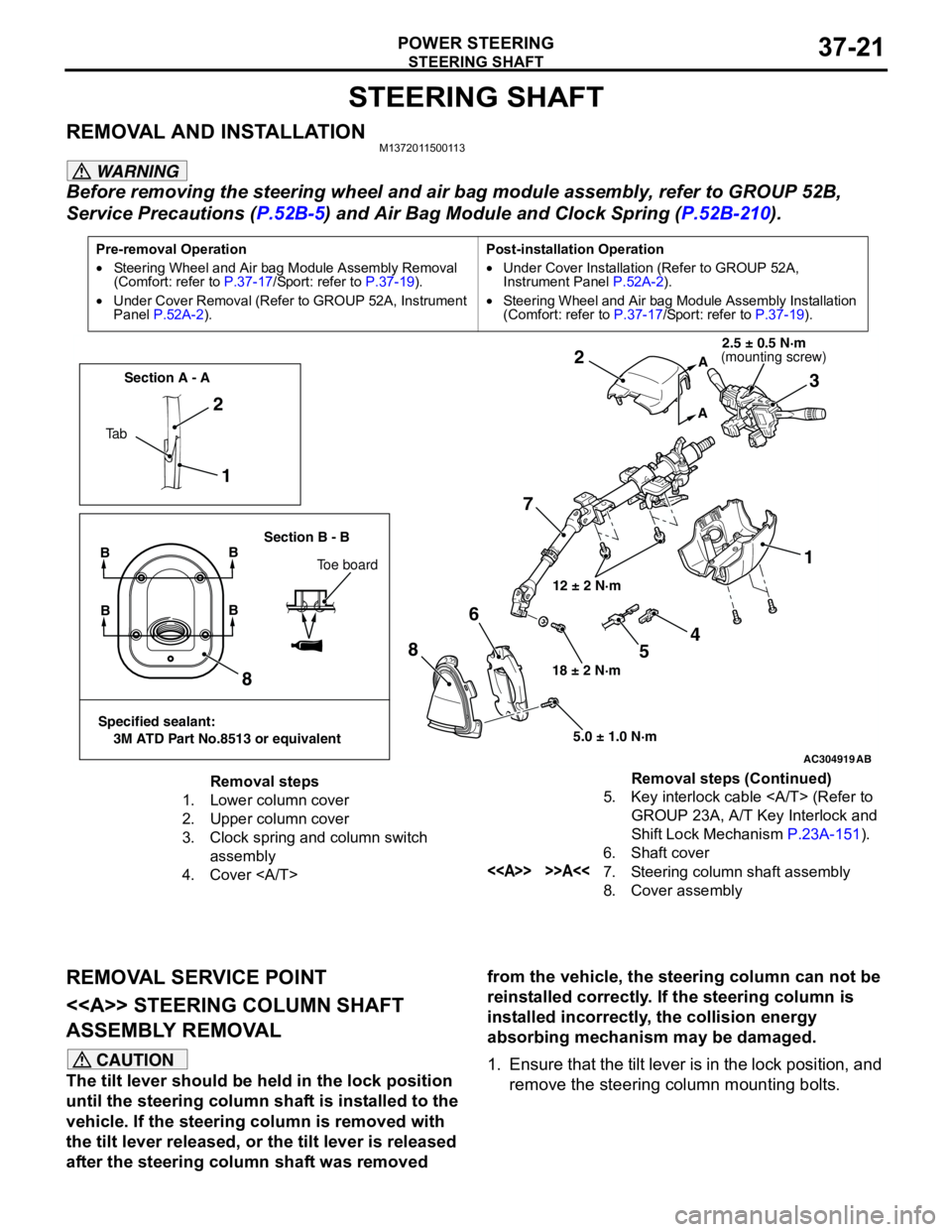
REMOVAL SERVICE POINT
<> STEERING COLUMN SHAFT
ASSEMBLY REMOVAL
CAUTION
The tilt lever should be held in the lock position
until the steering column shaft is installed to the
vehicle. If the steering column is removed with
the tilt lever released, or the tilt lever is released
after the steering column shaft was removed from the vehicle, the steering column can not be
reinstalled correctly. If the steering column is
installed incorrectly, the collision energy
absorbing mechanism may be damaged.
1. Ensure that the tilt lever is in the lock position, and
remove the steering column mounting bolts.
Pre-removal Operation
•Steering Wheel and Air bag Module Assembly Removal
(Comfort: refer to P.37-17/Sport: refer to P.37-19).
•Under Cover Removal (Refer to GROUP 52A, Instrument
Panel P.52A-2).Post-installation Operation
•Under Cover Installation (Refer to GROUP 52A,
Instrument Panel P.52A-2).
•Steering Wheel and Air bag Module Assembly Installation
(Comfort: refer to P.37-17/Sport: refer to P.37-19).
AC304919AB
12 ± 2 N·m
18 ± 2 N·m
5.0 ± 1.0 N·m
1 2
73 2
1
8
86
A
A
Ta bSection A - A
Section B - B
BB
Toe board
Specified sealant:
3M ATD Part No.8513 or equivalent
BB
4
5
(mounting screw)2.5 ± 0.5 N·m
Removal steps
1. Lower column cover
2. Upper column cover
3. Clock spring and column switch
assembly
4. Cover 5. Key interlock cable (Refer to
GROUP 23A, A/T Key Interlock and
Shift Lock Mechanism P.23A-151).
6. Shaft cover
<> >>A<<7. Steering column shaft assembly
8. Cover assemblyRemoval steps (Continued)
Page 280 of 788
42-2
TROUBLESHOOTING . . . . . . . . . .42-26
ON-VEHICLE SERVICE. . . . . . . . .42-27
DOOR FIT ADJUSTMENT. . . . . . . . . . . 42-27
DOOR WINDOW GLASS ADJUSTMENT42-28
GLASS SLIDING MECHANISM CHECK
AND ADJUSTMENT . . . . . . . . . . . . . . . 42-28
POWER WINDOW OPERATING
CURRENT CHECK . . . . . . . . . . . . . . . . 42-28
POWER WINDOW RELAY CHECK . . . 42-29
CIRCUIT BREAKER (INCORPORATED
IN THE POWER WINDOW MOTOR)
INSPECTION . . . . . . . . . . . . . . . . . . . . . 42-29
POWER WINDOW CHECK . . . . . . . . . . 42-29
CENTRAL DOOR LOCKING SYSTEM
INSPECTION . . . . . . . . . . . . . . . . . . . . . 42-29
DOOR OUTSIDE HANDLE PLAY
CHECK . . . . . . . . . . . . . . . . . . . . . . . . . 42-29
DOOR INSIDE HANDLE PLAY
ADJUSTMENT . . . . . . . . . . . . . . . . . . . . 42-30
DOOR ASSEMBLY . . . . . . . . . . . .42-31
REMOVAL AND INSTALLATION . . . . . 42-31
INSPECTION . . . . . . . . . . . . . . . . . . . . . 42-32
DOOR GLASS AND
REGULATOR . . . . . . . . . . . . . . . . .
42-32
REMOVAL AND INSTALLATION . . . . . 42-32
INSPECTION . . . . . . . . . . . . . . . . . . . . . 42-34
DOOR HANDLE AND LATCH . . . .42-36
REMOVAL AND INSTALLATION . . . . . 42-36
INSPECTION . . . . . . . . . . . . . . . . . . . . . 42-37
WINDOW GLASS RUNCHANNEL AND
DOOR OPENING
WEATHERSTRIP . . . . . . . . . . . . . .
42-39
REMOVAL AND INSTALLATION . . . . . 42-39
TRUNK LID . . . . . . . . . . . . . . . .42-41
SPECIAL TOOL . . . . . . . . . . . . . . .
42-41
ON-VEHICLE SERVICE. . . . . . . . .42-41
TRUNK LID ADJUSTMENT . . . . . . . . . . 42-41
ADJUSTMENT OF CLEARANCE
AROUND TRUNK LID . . . . . . . . . . . . . . 42-42
TRUNK LID STRIKER ADJUSTMENT . 42-42
TRUNK LID HEIGHT ADJUSTMENT . . 42-42
TRUNK LID . . . . . . . . . . . . . . . . . . .42-43
REMOVAL AND INSTALLATION . . . . . . 42-43
INSPECTION . . . . . . . . . . . . . . . . . . . . . 42-45
TAILGATE . . . . . . . . . . . . . . . . 42-46
SERVICE SPECIFICATIONS . . . . .
42-46
SEALANTS . . . . . . . . . . . . . . . . . . .42-46
SPECIAL TOOL . . . . . . . . . . . . . . .42-46
TROUBLESHOOTING . . . . . . . . . .42-46
ON-VEHICLE SERVICE . . . . . . . . .42-46
TAILGATE FIT ADJUSTMENT. . . . . . . . 42-46
TAILGATE HANDLE PLAY CHECK . . . . 42-47
TAILGATE . . . . . . . . . . . . . . . . . . .42-48
REMOVAL AND INSTALLATION . . . . . . 42-48
TAILGATE HANDLE AND
LATCH . . . . . . . . . . . . . . . . . . . . . .
42-50
REMOVAL AND INSTALLATION . . . . . . 42-50
INSPECTION . . . . . . . . . . . . . . . . . . . . . 42-51
KEYLESS ENTRY SYSTEM . . 42-51
SERVICE SPECIFICATIONS . . . . .
42-51
SPECIAL TOOLS . . . . . . . . . . . . . .42-52
TROUBLESHOOTING . . . . . . . . . .42-53
ON-VEHICLE SERVICE . . . . . . . . .42-53
KEYLESS ENTRY SYSTEM CHECK. . . 42-53
KEYLESS ENTRY SYSTEM TIMER
LOCK FUNCTION INSPECTION . . . . . . 42-53
ENABLING/DISABLING
THE ANSWERBACK FUNCTION . . . . . 42-53
HOW TO REGISTER SECRET CODE . 42-55
TRANSMITTER. . . . . . . . . . . . . . . .42-58
DISASSEMBLY AND REASSEMBLY . . 42-58
INSPECTION . . . . . . . . . . . . . . . . . . . . . 42-59
Page 307 of 788
DOOR
BODY42-29
3. If the operation current is outside the standard
value, refer to GROUP 54B, Troubleshooting
P.54B-17, refer to GROUP 54C, Troubleshooting
P.54C-4.
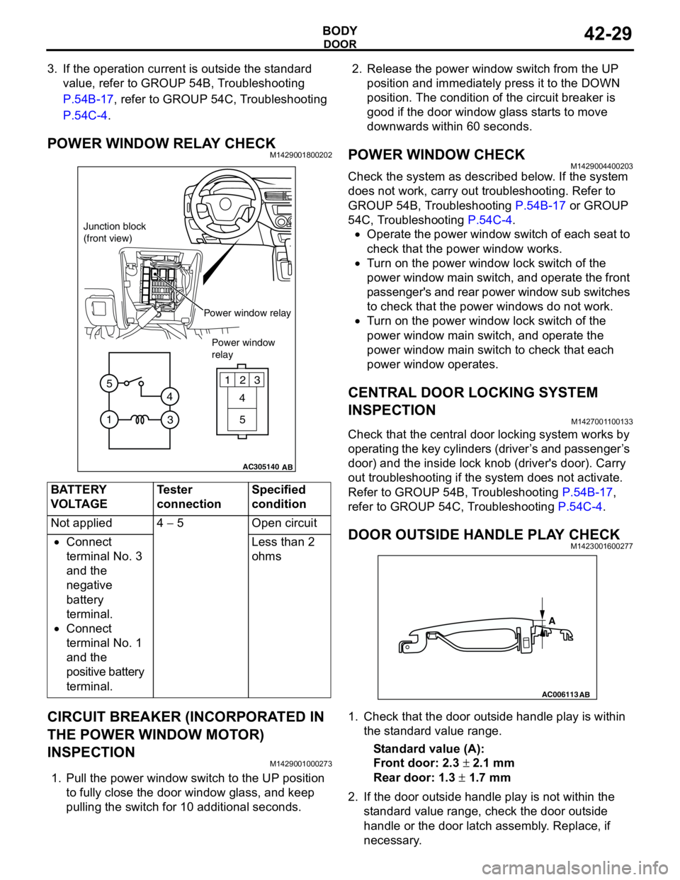
POWER WINDOW RELAY CHECKM1429001800202
CIRCUIT BREAKER (INCORPORATED IN
THE POWER WINDOW MOTOR)
INSPECTION
M1429001000273
1. Pull the power window switch to the UP position
to fully close the door window glass, and keep
pulling the switch for 10 additional seconds.2. Release the power window switch from the UP
position and immediately press it to the DOWN
position. The condition of the circuit breaker is
good if the door window glass starts to move
downwards within 60 seconds.
POWER WINDOW CHECKM1429004400203
Check the system as described below. If the system
does not work, carry out troubleshooting. Refer to
GROUP 54B, Troubleshooting P.54B-17 or GROUP
54C, Troubleshooting P.54C-4.
•Operate the power window switch of each seat to
check that the power window works.
•Turn on the power window lock switch of the
power window main switch, and operate the front
passenger's and rear power window sub switches
to check that the power windows do not work.
•Turn on the power window lock switch of the
power window main switch, and operate the
power window main switch to check that each
power window operates.
CENTRAL DOOR LOCKING SYSTEM
INSPECTION
M1427001100133
Check that the central door locking system works by
operating the key cylinders (driver’s and passenger’s
door) and the inside lock knob (driver's door). Carry
out troubleshooting if the system does not activate.
Refer to GROUP 54B, Troubleshooting P.54B-17,
refer to GROUP 54C, Troubleshooting P.54C-4.
DOOR OUTSIDE HANDLE PLAY CHECKM1423001600277
1. Check that the door outside handle play is within
the standard value range.
Standard value (A):
Front door: 2.3 ± 2.1 mm
Rear door: 1.3 ± 1.7 mm
2. If the door outside handle play is not within the
standard value range, check the door outside
handle or the door latch assembly. Replace, if
necessary. BATTERY
VOLTAGETester
connectionSpecified
condition
Not applied 4 − 5 Open circuit
•Connect
terminal No. 3
and the
negative
battery
terminal.
•Connect
terminal No. 1
and the
positive battery
terminal.Less than 2
ohms
AC305140
123
4
5
1
3 4 5
AB
Junction block
(front view)
Power window relay
Power window
relay
AC006113
AB
A
Page 314 of 788
DOOR
BODY42-36
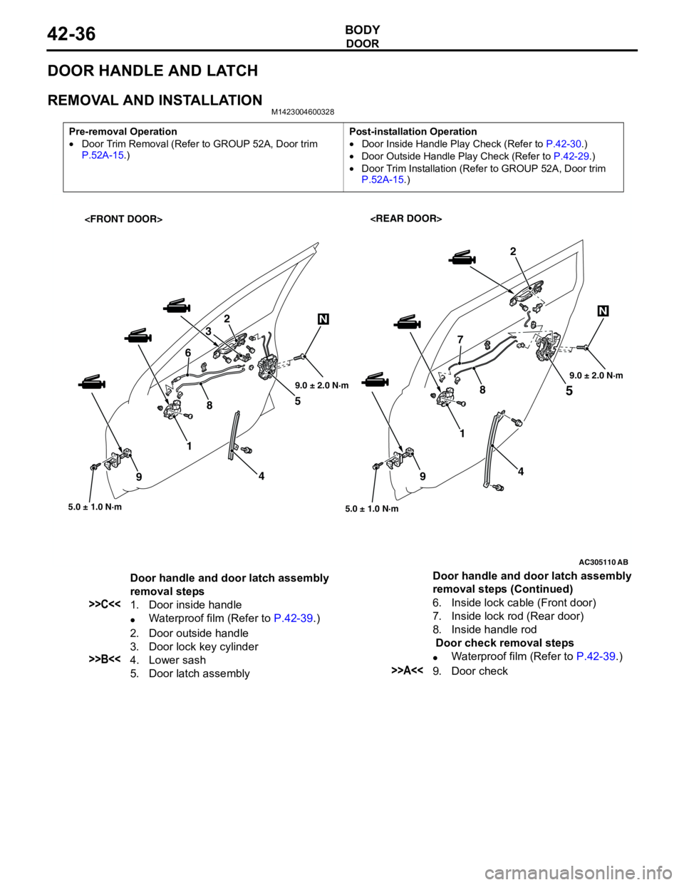
DOOR HANDLE AND LATCH
REMOVAL AND INSTALLATIONM1423004600328
Pre-removal Operation
•Door Trim Removal (Refer to GROUP 52A, Door trim
P.52A-15.)Post-installation Operation
•Door Inside Handle Play Check (Refer to P.42-30.)
•Door Outside Handle Play Check (Refer to P.42-29.)
•Door Trim Installation (Refer to GROUP 52A, Door trim
P.52A-15.)
AC305110
5
5.0 ± 1.0 N·m
1
4
9
2
AB
45 2
3
87
5.0 ± 1.0 N·m
1 6
9
NN
89.0 ± 2.0 N·m9.0 ± 2.0 N·m
Door handle and door latch assembly
removal steps
>>C<<1. Door inside handle
•Waterproof film (Refer to P.42-39.)
2. Door outside handle
3. Door lock key cylinder
>>B<<4. Lower sash
5. Door latch assembly6. Inside lock cable (Front door)
7. Inside lock rod (Rear door)
8. Inside handle rod
Door check removal steps
•Waterproof film (Refer to P.42-39.)>>A<<9. Door check Door handle and door latch assembly
removal steps (Continued)
Page 316 of 788
DOOR
BODY42-38
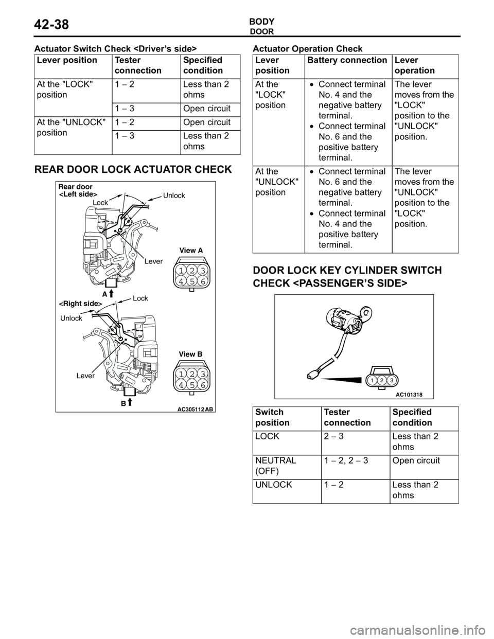
Actuator Switch Check
REAR DOOR LOCK ACTUATOR CHECK
Actuator Operation Check
DOOR LOCK KEY CYLINDER SWITCH
CHECK
Lever position Tester
connectionSpecified
condition
At the "LOCK"
position1 − 2 Less than 2
ohms
1 − 3 Open circuit
At the "UNLOCK"
position1 − 2 Open circuit
1 − 3 Less than 2
ohms
23
41
56
23
41
56
AC305112B
A
AB
Rear door
LockUnlock
View A
View B UnlockLock
Lever
Lever
positionBattery connection Lever
operation
At the
"LOCK"
position•Connect terminal
No. 4 and the
negative battery
terminal.
•Connect terminal
No. 6 and the
positive battery
terminal.The lever
moves from the
"LOCK"
position to the
"UNLOCK"
position.
At the
"UNLOCK"
position•Connect terminal
No. 6 and the
negative battery
terminal.
•Connect terminal
No. 4 and the
positive battery
terminal.The lever
moves from the
"UNLOCK"
position to the
"LOCK"
position.
Switch
positionTester
connectionSpecified
condition
LOCK 2 − 3 Less than 2
ohms
NEUTRAL
(OFF)1 − 2, 2 − 3 Open circuit
UNLOCK 1 − 2 Less than 2
ohms
AC101318
3 2 1
Page 328 of 788
TA I L G AT E
BODY42-50
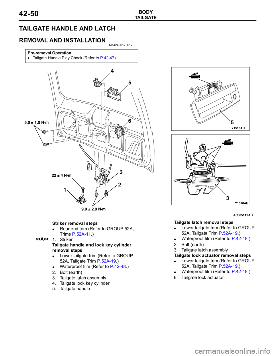
TAILGATE HANDLE AND LATCH
REMOVAL AND INSTALLATIONM1424001700170
Pre-removal Operation
•Tailgate Handle Play Check (Refer to P.42-47).
Y1518AU
Y1520AU
AC305141
4
5
6
3 35
5.0 ± 1.0 N·m
9.0 ± 2.0 N·m
AB
2
1
22 ± 4 N·m
Striker removal steps
•Rear end trim (Refer to GROUP 52A,
Trims P.52A-11.)
>>A<<1. Striker
Tailgate handle and lock key cylinder
removal steps
•Lower tailgate trim (Refer to GROUP
52A, Tailgate Trim P.52A-19.)
•Waterproof film (Refer to P.42-48.)
2. Bolt (earth)
3. Tailgate latch assembly
4. Tailgate lock key cylinder
5. Tailgate handleTailgate latch removal steps
•Lower tailgate trim (Refer to GROUP
52A, Tailgate Trim P.52A-19.)
•Waterproof film (Refer to P.42-48.)
2. Bolt (earth)
3. Tailgate latch assembly
Tailgate lock actuator removal steps
•Lower tailgate trim (Refer to GROUP
52A, Tailgate Trim P.52A-19.)
•Waterproof film (Refer to P.42-48.)
6. Tailgate lock actuator
Page 329 of 788
KEYLESS ENTRY SYSTEM
BODY42-51
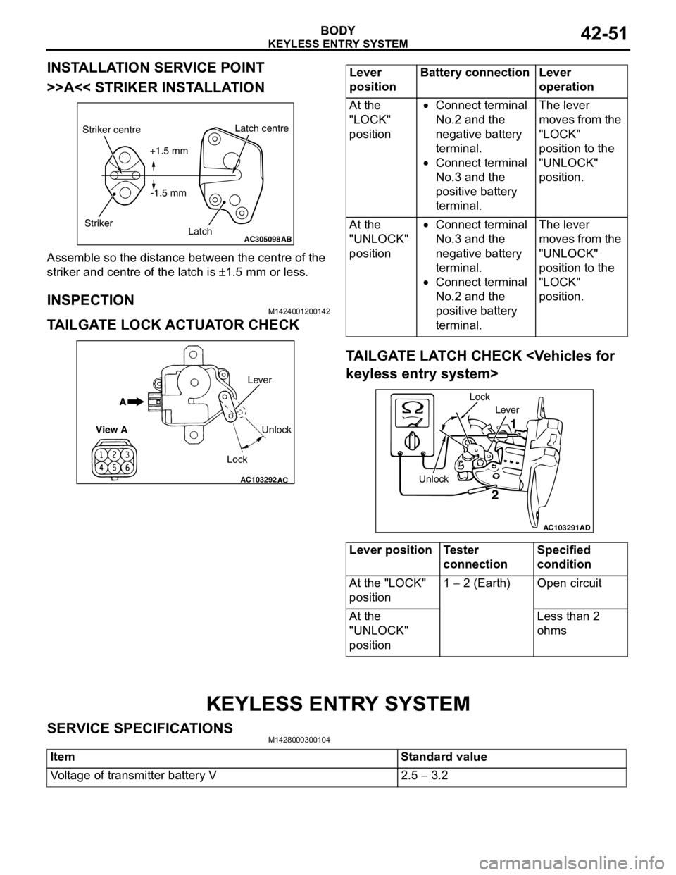
INSTALLATION SERVICE POINT
>>A<< STRIKER INSTALLATION
Assemble so the distance between the centre of the
striker and centre of the latch is ±1.5 mm or less.
INSPECTIONM1424001200142
TAILGATE LOCK ACTUATOR CHECK
TAILGATE LATCH CHECK
KEYLESS ENTRY SYSTEM
SERVICE SPECIFICATIONSM1428000300104
AC305098AB
Striker centre
StrikerLatch centre
Latch +1.5 mm
-1.5 mm
AC103292
A
View A
Unlock
Lock Lever
AC
Lever
positionBattery connection Lever
operation
At the
"LOCK"
position•Connect terminal
No.2 and the
negative battery
terminal.
•Connect terminal
No.3 and the
positive battery
terminal.The lever
moves from the
"LOCK"
position to the
"UNLOCK"
position.
At the
"UNLOCK"
position•Connect terminal
No.3 and the
negative battery
terminal.
•Connect terminal
No.2 and the
positive battery
terminal.The lever
moves from the
"UNLOCK"
position to the
"LOCK"
position.
Lever position Tester
connectionSpecified
condition
At the "LOCK"
position1 − 2 (Earth) Open circuit
At the
"UNLOCK"
positionLess than 2
ohms
AC103291
Lever
Unlock Lock
1
2
AD
Item Standard value
Voltage of transmitter battery V 2.5 − 3.2
Page 330 of 788
KEYLESS ENTRY SYSTEM
BODY42-52
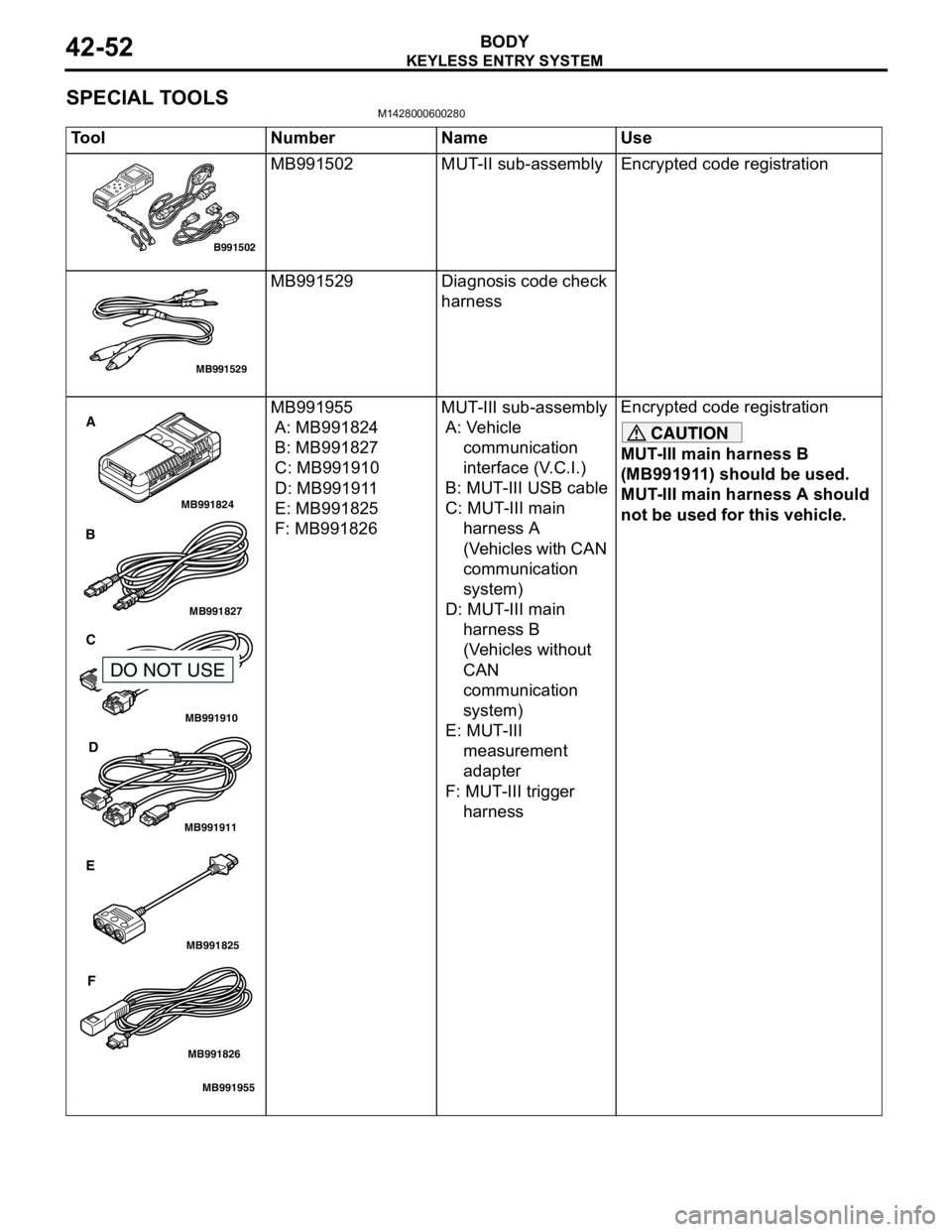
SPECIAL TOOLSM1428000600280
Tool Number Name Use
MB991502 MUT-II sub-assembly Encrypted code registration
MB991529 Diagnosis code check
harness
MB991955
A: MB991824
B: MB991827
C: MB991910
D: MB991911
E: MB991825
F: MB991826MUT-III sub-assembly
A: Vehicle
communication
interface (V.C.I.)
B: MUT-III USB cable
C: MUT-III main
harness A
(Vehicles with CAN
communication
system)
D: MUT-III main
harness B
(Vehicles without
CAN
communication
system)
E: MUT-III
measurement
adapter
F: MUT-III trigger
harnessEncrypted code registration
CAUTION
MUT-III main harness B
(MB991911) should be used.
MUT-III main harness A should
not be used for this vehicle.
B991502
MB991529
MB991910
MB991826
MB991955
MB991911
MB991824
MB991827
MB991825
A
B
C
D
E
F
DO NOT USE
Page 331 of 788
KEYLESS ENTRY SYSTEM
BODY42-53
TROUBLESHOOTINGM1428000700287
The keyless entry system is controlled by the Smart
Wiring System (SWS). For troubleshooting, refer to
GROUP 54B, Troubleshooting P.54B-17 or GROUP
54C, Troubleshooting P.54C-4.
ON-VEHICLE SERVICE
KEYLESS ENTRY SYSTEM CHECKM1428001400096
Check the system as described below. If the system
does not work, carry out troubleshooting. Refer to
GROUP 54B, Troubleshooting P.54B-17, refer to
GROUP 54C, Troubleshooting P.54C-4.
•Operate the transmitter to check that the doors
and tailgate can be locked and unlocked.
•Operate the transmitter to check that the
answerback function works in response to door
and tailgate
NOTE: The adjustment function allows you to
change the answerback setting as follows. Prior
to that check, confirm which setting is activated.
.
•The hazard warning lamps flash twice when
locked and once when unlocked. The room
lamp flashes twice when locked and
illuminates for 15 seconds when unlocked.
•The hazard warning lamps do not flash when
locked and flash once when unlocked. The
room lamp flashes twice when locked and
illuminates for 15 seconds when unlocked.
•The hazard warning lamps flash twice when
locked and do not flash when unlocked. The
room lamp flashes twice when locked and
illuminates for 15 seconds when unlocked.
•The hazard warning lamps do not flash when
both locked and unlocked. The room lamp
flashes twice when locked and illuminates for
15 seconds when unlocked.
KEYLESS ENTRY SYSTEM TIMER LOCK
FUNCTION INSPECTION
M1428004000138
Push the transmitter unlock button and check to see
that the doors and tailgate
seconds. If it doesn't, then execute troubleshooting
remedies. Refer to GROUP 54B, Troubleshooting
P.54B-17, refer to GROUP 54C, Troubleshooting
P.54C-4.
ENABLING/DISABLING THE
ANSWERBACK FUNCTION
M1428003200214
If the keyless entry system locks or unlocks the
doors, the room lamp flashes or illuminates, the
hazard warning lamp flashes (hazard answerback
function). The hazard answerback function can be
enabled or disabled according to the following
procedure:
ENABLING/DISABLING THE HAZARD
ANSWERBACK FUNCTION
The hazard answerback function can be enabled or
disabled by one of the two following procedures.
1. Enter the hazard answerback customize mode by
performing one of the following steps. If the
ETACS-ECU enters the customize mode, its
buzzer will sound once.
(1) Turn the ignition switch to “LOCK”(OFF)
position.
(2) Turn off the hazard warning lamp switch.
CAUTION
Before connecting or disconnecting the earth,
turn the ignition switch to the "LOCK" (OFF)
position.
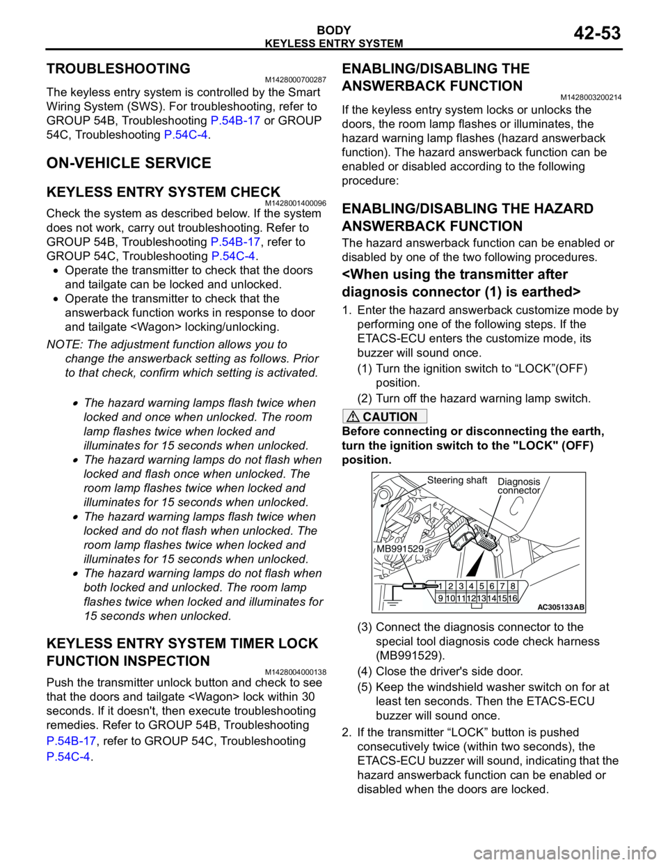
(3) Connect the diagnosis connector to the
special tool diagnosis code check harness
(MB991529).
(4) Close the driver's side door.
(5) Keep the windshield washer switch on for at
least ten seconds. Then the ETACS-ECU
buzzer will sound once.
2. If the transmitter “LOCK” button is pushed
consecutively twice (within two seconds), the
ETACS-ECU buzzer will sound, indicating that the
hazard answerback function can be enabled or
disabled when the doors are locked.
AC305133AB
Diagnosis
connector
MB991529Steering shaft