ect MITSUBISHI LANCER 2005 Owner's Guide
[x] Cancel search | Manufacturer: MITSUBISHI, Model Year: 2005, Model line: LANCER, Model: MITSUBISHI LANCER 2005Pages: 788, PDF Size: 45.98 MB
Page 45 of 788
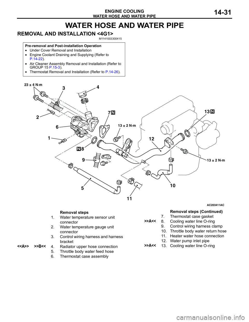
WATER HOSE AND WATER PIPE
ENGINE COOLING14-31
WATER HOSE AND WATER PIPE
REMOVAL AND INSTALLATION <4G1>M1141003300415
Pre-removal and Post-installation Operation
•Under Cover Removal and Installation
•Engine Coolant Draining and Supplying (Refer to
P.14-22).
•Air Cleaner Assembly Removal and Installation (Refer to
GROUP 15 P.15-3).
•Thermostat Removal and Installation (Refer to P.14-26).
AC203411
1 234
5 67
8
10 9
13 ± 2 N·m 23 ± 4 N·m
13 ± 2 N·m
N
N
AC
111213
N
Removal steps
1. Water temperature sensor unit
connector
2. Water temperature gauge unit
connector
3. Control wiring harness and harness
bracket
<> >>B<<4. Radiator upper hose connection
5. Throttle body water feed hose
6. Thermostat case assembly7. Thermostat case gasket
>>A<<8. Cooling water line O-ring
9. Control wiring harness clamp
10. Throttle body water return hose
11. Heater water hose connection
12. Water pump inlet pipe
>>A<<13. Cooling water line O-ringRemoval steps (Continued)
Page 46 of 788
Page 47 of 788
WATER HOSE AND WATER PIPE
ENGINE COOLING14-33
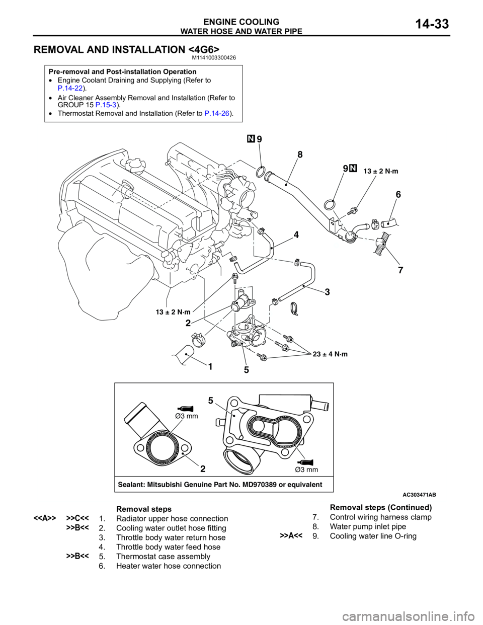
REMOVAL AND INSTALLATION <4G6>M1141003300426
Pre-removal and Post-installation Operation
•Engine Coolant Draining and Supplying (Refer to
P.14-22).
•Air Cleaner Assembly Removal and Installation (Refer to
GROUP 15 P.15-3).
•Thermostat Removal and Installation (Refer to P.14-26).
AC303471
1 23 4
56
7 8 9
9
13 ± 2 N·m
23 ± 4 N·m 13 ± 2 N·m
N
N
AB
2
Sealant: Mitsubishi Genuine Part No. MD970389 or equivalentØ3 mm
Ø3 mm
5
Removal steps
<> >>C<<1. Radiator upper hose connection
>>B<<2. Cooling water outlet hose fitting
3. Throttle body water return hose
4. Throttle body water feed hose
>>B<<5. Thermostat case assembly
6. Heater water hose connection7. Control wiring harness clamp
8. Water pump inlet pipe
>>A<<9. Cooling water line O-ringRemoval steps (Continued)
Page 48 of 788
Page 50 of 788
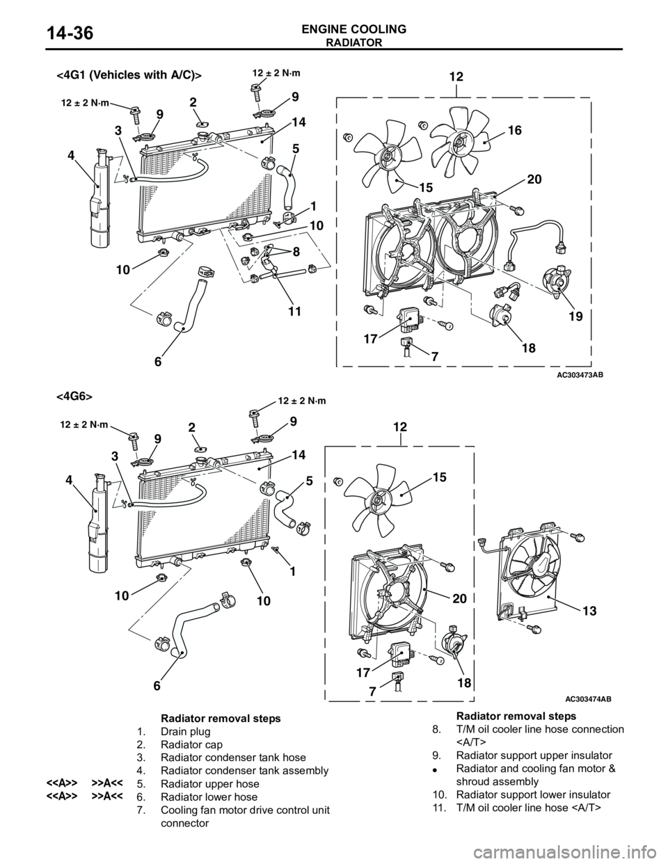
RADIATOR
ENGINE COOLING14-36
AC303473
18 171520 12
9
14
5 2
9
3
4
1
10
6 10
12 ± 2 N·m
AB
12 ± 2 N·m<4G1 (Vehicles with A/C)>
16
19
8
11
7
AC303474
18 1715
20 12 9
14
5 2
9
3
4
1
10
6 10
12 ± 2 N·m
AB
<4G6>
13
7
12 ± 2 N·m
Radiator removal steps
1. Drain plug
2. Radiator cap
3. Radiator condenser tank hose
4. Radiator condenser tank assembly
<> >>A<<5. Radiator upper hose
<> >>A<<6. Radiator lower hose
7. Cooling fan motor drive control unit
connector8. T/M oil cooler line hose connection
9. Radiator support upper insulator
•Radiator and cooling fan motor &
shroud assembly
10. Radiator support lower insulator
11. T/M oil cooler line hose Radiator removal steps
Page 51 of 788

RADIATOR
ENGINE COOLING14-37
REMOVAL SERVICE POINT
<> RADIATOR UPPER
HOSE/RADIATOR LOWER HOSE
DISCONNECTION
Make mating marks on the radiator hose and the
hose clamp. Disconnect the radiator hoses.
INSTALLATION SERVICE POINT
>>A<< RADIATOR LOWER
HOSE/RADIATOR UPPER HOSE
CONNECTION
1. Insert radiator lower hose as far as the projection
of the cooling water inlet hose fitting.
2. Insert radiator upper hose as far as the projection
of the thermostat case assembly <4G1> or the
cooling water outlet hose fitting <4G6>.
3. Align the mating marks on the radiator hose and
hose clamp, and then connect the radiator hose.
12. Cooling fan motor & shroud
assembly
13. A/C condenser fan motor & shroud
assembly <4G6>
14. Radiator assembly
Cooling fan motor removal
steps
3. Radiator condenser tank hose
<> >>A<<5. Radiator upper hose
7. Cooling fan motor drive control unit
connector Radiator removal steps
12. Cooling fan motor & shroud
assembly
15. Cooling fan (L.H.)
16. Cooling fan (R.H.) <4G1 (Vehicles
with A/C)>
17. Cooling fan motor drive control unit
18. Cooling fan motor (L.H.)
19. Cooling fan (R.H.) motor <4G1
(Vehicles with A/C)>
20. Cooling fan shroudCooling fan motor removal steps
(Continued)
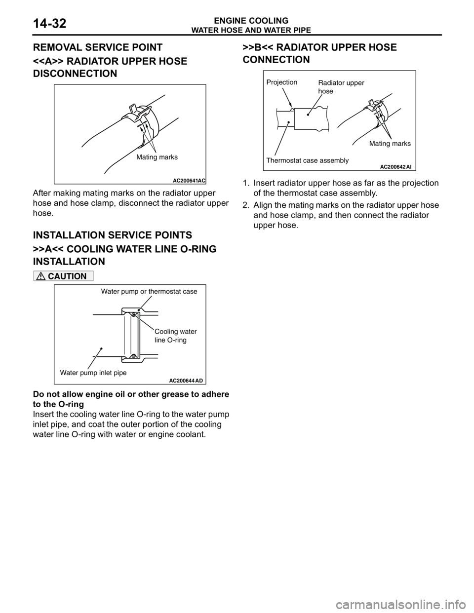
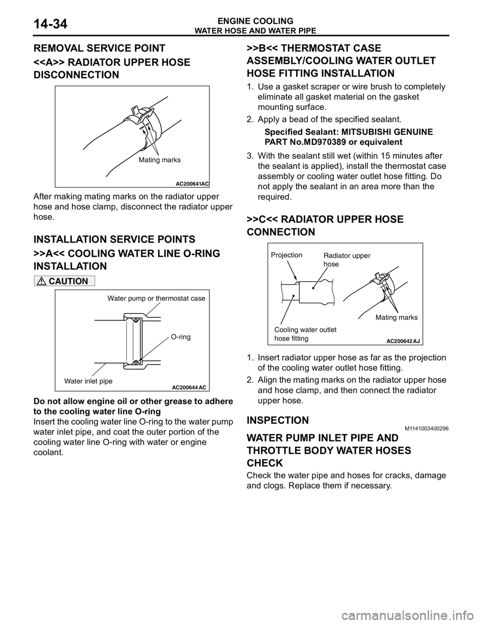
AC200641AC
Mating marks
AC200642
Mating marks
Projection
Cooling water hose fitting
or thermostat case assembly
AK
Radiator hose
Page 53 of 788
15-1
GROUP 15
INTAKE AND
EXHAUST
CONTENTS
GENERAL INFORMATION . . . . . . . .15-2
SERVICE SPECIFICATION . . . . . . . .15-2
SPECIAL TOOL . . . . . . . . . . . . . . . . .15-2
AIR CLEANER . . . . . . . . . . . . . . . . . .15-3
REMOVAL AND INSTALLATION . . . . . . . . 15-3
INLET MANIFOLD . . . . . . . . . . . . . . .15-5
REMOVAL AND INSTALLATION <4G1> . . 15-5REMOVAL AND INSTALLATION <4G6> . . 15-6
INSPECTION . . . . . . . . . . . . . . . . . . . . . . . . 15-7
EXHAUST MANIFOLD . . . . . . . . . . . .15-7
REMOVAL AND INSTALLATION <4G1> . . 15-7
REMOVAL AND INSTALLATION <4G6> . . 15-9
INSPECTION . . . . . . . . . . . . . . . . . . . . . . . . 15-10
EXHAUST PIPE AND MAIN
MUFFLER . . . . . . . . . . . . . . . . . . . . . .15-11
REMOVAL AND INSTALLATION . . . . . . . . 15-11
Page 56 of 788
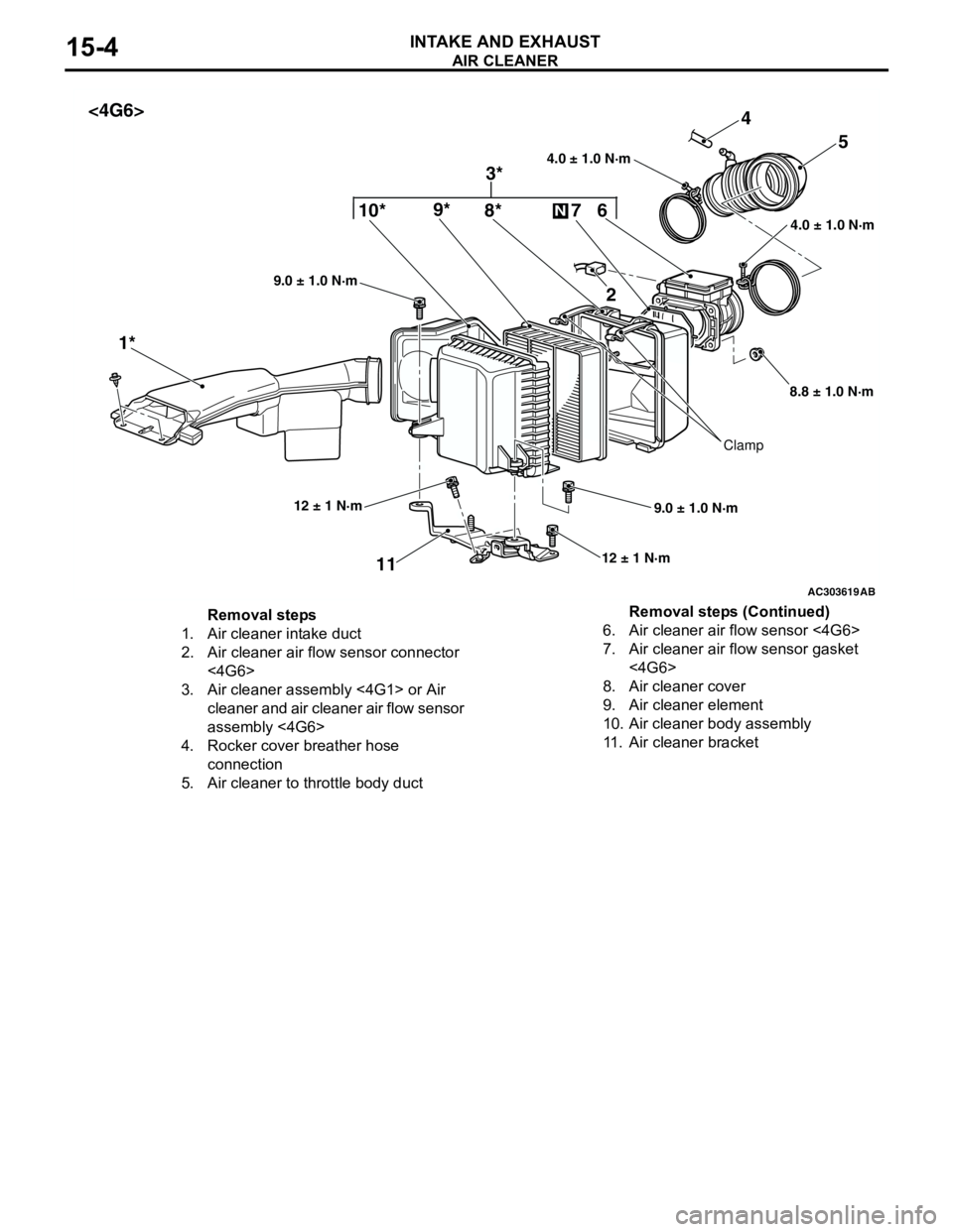
AIR CLEANER
INTAKE AND EXHAUST15-4
AC303619
4.0 ± 1.0 N·m 4.0 ± 1.0 N·m10*9*4
1*5
11
12 ± 1 N·m
9.0 ± 1.0 N·m 9.0 ± 1.0 N·m
AB
12 ± 1 N·m
Clamp
8*
3* <4G6>
6 7
N
2
8.8 ± 1.0 N·m
Removal steps
1. Air cleaner intake duct
2. Air cleaner air flow sensor connector
<4G6>
3. Air cleaner assembly <4G1> or Air
cleaner and air cleaner air flow sensor
assembly <4G6>
4. Rocker cover breather hose
connection
5. Air cleaner to throttle body duct6. Air cleaner air flow sensor <4G6>
7. Air cleaner air flow sensor gasket
<4G6>
8. Air cleaner cover
9. Air cleaner element
10. Air cleaner body assembly
11. Air cleaner bracketRemoval steps (Continued)
Page 57 of 788
INLET MANIFOLD
INTAKE AND EXHAUST15-5
INLET MANIFOLD
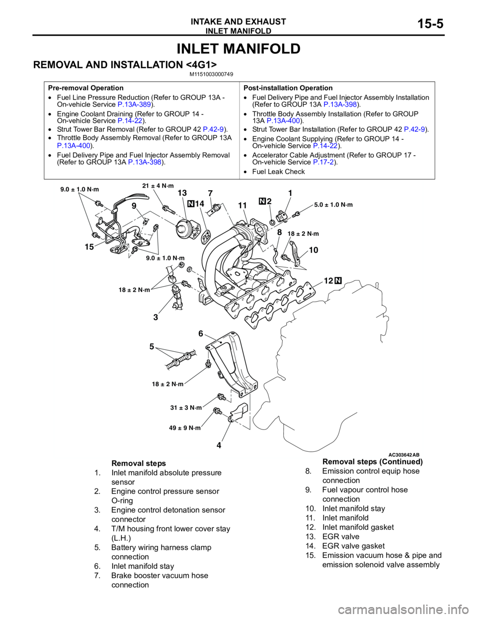
REMOVAL AND INSTALLATION <4G1>M1151003000749
Pre-removal Operation
•Fuel Line Pressure Reduction (Refer to GROUP 13A -
On-vehicle Service P.13A-389).
•Engine Coolant Draining (Refer to GROUP 14 -
On-vehicle Service P.14-22).
•Strut Tower Bar Removal (Refer to GROUP 42 P.42-9).
•Throttle Body Assembly Removal (Refer to GROUP 13A
P.13A-400).
•Fuel Delivery Pipe and Fuel Injector Assembly Removal
(Refer to GROUP 13A P.13A-398).Post-installation Operation
•Fuel Delivery Pipe and Fuel Injector Assembly Installation
(Refer to GROUP 13A P.13A-398).
•Throttle Body Assembly Installation (Refer to GROUP
13A P.13A-400).
•Strut Tower Bar Installation (Refer to GROUP 42 P.42-9).
•Engine Coolant Supplying (Refer to GROUP 14 -
On-vehicle Service P.14-22).
•Accelerator Cable Adjustment (Refer to GROUP 17 -
On-vehicle Service P.17-2).
•Fuel Leak Check
AC303642AB
15
3
6
5
412 10 71
2
11
913
14
21 ± 4 N·m
9.0 ± 1.0 N·m
9.0 ± 1.0 N·m
18 ± 2 N·m
18 ± 2 N·m18 ± 2 N·m5.0 ± 1.0 N·m
31 ± 3 N·m
49 ± 9 N·m
N
N
N
8
Removal steps
1. Inlet manifold absolute pressure
sensor
2. Engine control pressure sensor
O-ring
3. Engine control detonation sensor
connector
4. T/M housing front lower cover stay
(L.H.)
5. Battery wiring harness clamp
connection
6. Inlet manifold stay
7. Brake booster vacuum hose
connection8. Emission control equip hose
connection
9. Fuel vapour control hose
connection
10. Inlet manifold stay
11. Inlet manifold
12. Inlet manifold gasket
13. EGR valve
14. EGR valve gasket
15. Emission vacuum hose & pipe and
emission solenoid valve assembly Removal steps (Continued)
Page 58 of 788
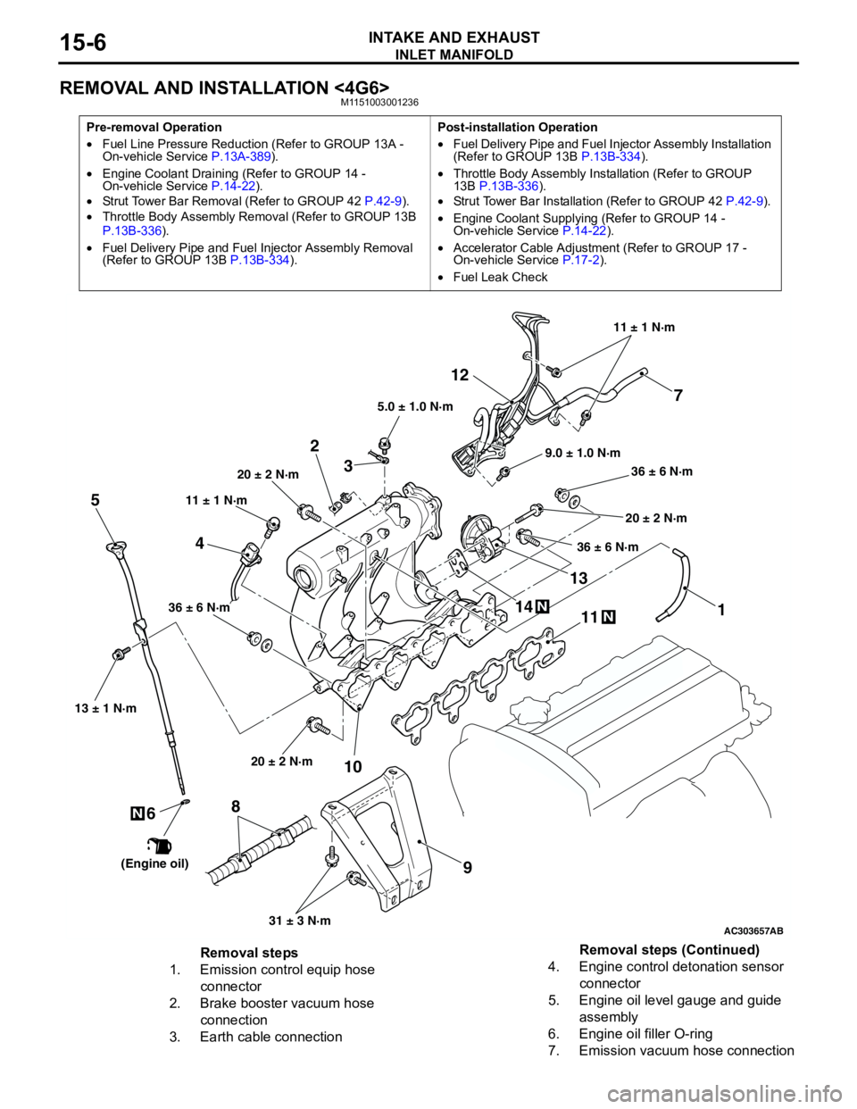
INLET MANIFOLD
INTAKE AND EXHAUST15-6
REMOVAL AND INSTALLATION <4G6>M1151003001236
Pre-removal Operation
•Fuel Line Pressure Reduction (Refer to GROUP 13A -
On-vehicle Service P.13A-389).
•Engine Coolant Draining (Refer to GROUP 14 -
On-vehicle Service P.14-22).
•Strut Tower Bar Removal (Refer to GROUP 42 P.42-9).
•Throttle Body Assembly Removal (Refer to GROUP 13B
P.13B-336).
•Fuel Delivery Pipe and Fuel Injector Assembly Removal
(Refer to GROUP 13B P.13B-334).Post-installation Operation
•Fuel Delivery Pipe and Fuel Injector Assembly Installation
(Refer to GROUP 13B P.13B-334).
•Throttle Body Assembly Installation (Refer to GROUP
13B P.13B-336).
•Strut Tower Bar Installation (Refer to GROUP 42 P.42-9).
•Engine Coolant Supplying (Refer to GROUP 14 -
On-vehicle Service P.14-22).
•Accelerator Cable Adjustment (Refer to GROUP 17 -
On-vehicle Service P.17-2).
•Fuel Leak Check
AC303657
9.0 ± 1.0 N·m11 ± 1 N·m
20 ± 2 N·m
31 ± 3 N·m 36 ± 6 N·m
20 ± 2 N·m
20 ± 2 N·m
36 ± 6 N·m
36 ± 6 N·m
11
9 10 212
N1413N
AB
5.0 ± 1.0 N·m
3
1
11 ± 1 N·m
4
N
13 ± 1 N·m
5
6
(Engine oil)
7
8
Removal steps
1. Emission control equip hose
connector
2. Brake booster vacuum hose
connection
3. Earth cable connection4. Engine control detonation sensor
connector
5. Engine oil level gauge and guide
assembly
6. Engine oil filler O-ring
7. Emission vacuum hose connectionRemoval steps (Continued)