torque MITSUBISHI LANCER 2005 Owner's Guide
[x] Cancel search | Manufacturer: MITSUBISHI, Model Year: 2005, Model line: LANCER, Model: MITSUBISHI LANCER 2005Pages: 788, PDF Size: 45.98 MB
Page 243 of 788
SPECIAL TOOLS
POWER STEERING37-9
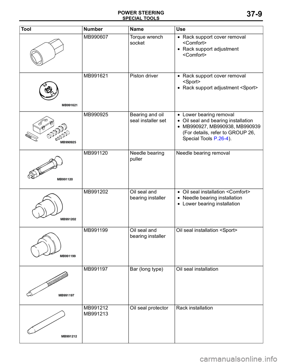
MB990607 Torque wrench
socket•Rack support cover removal
•Rack support adjustment
MB991621 Piston driver•Rack support cover removal
•Rack support adjustment
MB990925 Bearing and oil
seal installer set•Lower bearing removal
•Oil seal and bearing installation
•MB990927, MB990938, MB990939
(For details, refer to GROUP 26,
Special Tools P.26-4).
MB991120 Needle bearing
pullerNeedle bearing removal
MB991202 Oil seal and
bearing installer•Oil seal installation
•Needle bearing installation
•Lower bearing installation
MB991199 Oil seal and
bearing installerOil seal installation
MB991197 Bar (long type) Oil seal installation
MB991212
MB991213Oil seal protector Rack installation Tool Number Name Use
MB991621
MB990925
MB991120
MB991202
MB991199
AB
MB991197
MB991212
Page 244 of 788
SPECIAL TOOLS
POWER STEERING37-10
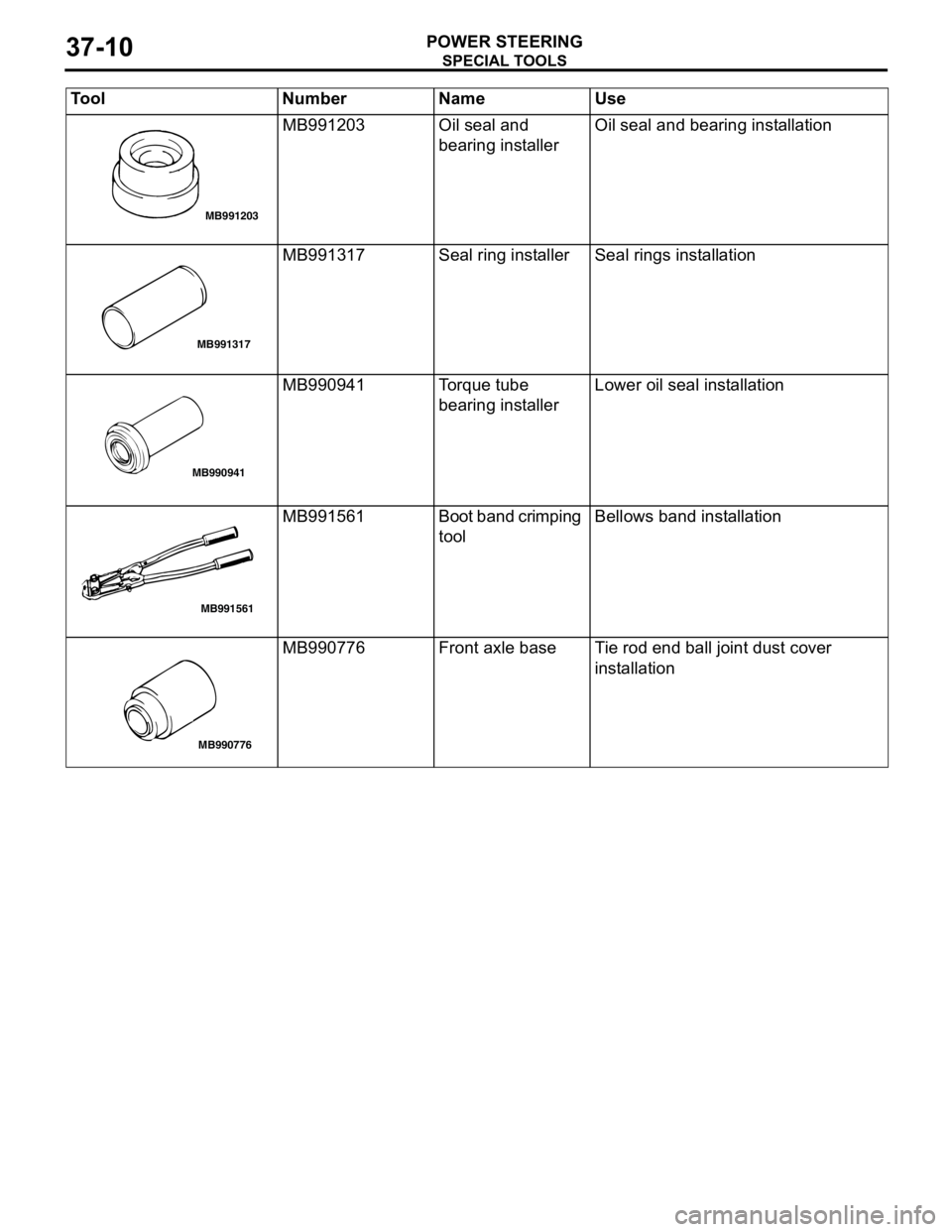
MB991203 Oil seal and
bearing installerOil seal and bearing installation
MB991317 Seal ring installer Seal rings installation
MB990941 Torque tube
bearing installerLower oil seal installation
MB991561 Boot band crimping
toolBellows band installation
MB990776 Front axle base Tie rod end ball joint dust cover
installation Tool Number Name Use
MB991203
MB991317
MB990941
MB991561
MB990776
Page 245 of 788
ON-VEHICLE SERVICE
POWER STEERING37-11
ON-VEHICLE SERVICE
STEERING WHEEL FREE PLAY CHECKM1372001000311
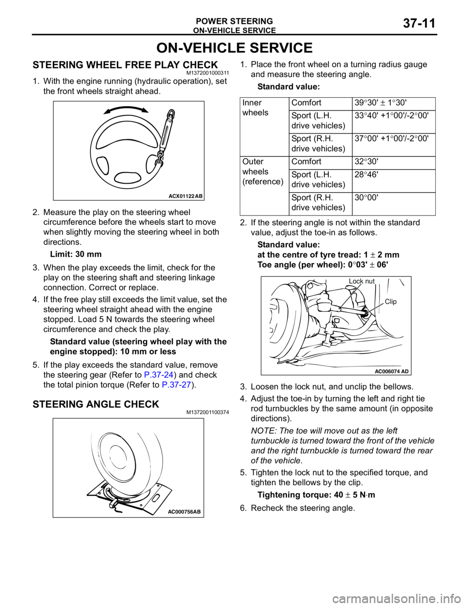
1. With the engine running (hydraulic operation), set
the front wheels straight ahead.
2. Measure the play on the steering wheel
circumference before the wheels start to move
when slightly moving the steering wheel in both
directions.
Limit: 30 mm
3. When the play exceeds the limit, check for the
play on the steering shaft and steering linkage
connection. Correct or replace.
4. If the free play still exceeds the limit value, set the
steering wheel straight ahead with the engine
stopped. Load 5 N towards the steering wheel
circumference and check the play.
Standard value (steering wheel play with the
engine stopped): 10 mm or less
5. If the play exceeds the standard value, remove
the steering gear (Refer to P.37-24) and check
the total pinion torque (Refer to P.37-27).
STEERING ANGLE CHECKM1372001100374
1. Place the front wheel on a turning radius gauge
and measure the steering angle.
Standard value:
2. If the steering angle is not within the standard
value, adjust the toe-in as follows.
Standard value:
at the centre of tyre tread: 1 ± 2 mm
Toe angle (per wheel): 0°03' ± 06'
3. Loosen the lock nut, and unclip the bellows.
4. Adjust the toe-in by turning the left and right tie
rod turnbuckles by the same amount (in opposite
directions).
NOTE: The toe will move out as the left
turnbuckle is turned toward the front of the vehicle
and the right turnbuckle is turned toward the rear
of the vehicle.
5. Tighten the lock nut to the specified torque, and
tighten the bellows by the clip.
Tightening torque: 40 ± 5 N⋅m
6. Recheck the steering angle.
ACX01122
AB
AC000756AB
Inner
wheelsComfort 39°30' ± 1°30'
Sport (L.H.
drive vehicles)33°40' +1°00'/-2°00'
Sport (R.H.
drive vehicles)37°00' +1°00'/-2°00'
Outer
wheels
(reference)Comfort 32°30'
Sport (L.H.
drive vehicles)28°46'
Sport (R.H.
drive vehicles)30°00'
AC006074AD
Lock nut
Clip
Page 246 of 788
ON-VEHICLE SERVICE
POWER STEERING37-12
TIE ROD END BALL JOINT TURNING
TORQUE CHECK
M1372001500297
CAUTION
•Do not remove the tie rod end nut from the
ball joint. Loosen it and use special tool to
avoid possible damage to the ball joint
threads.
•Hang special tool with cord to prevent it from
falling.
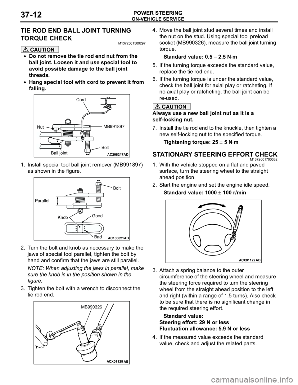
1. Install special tool ball joint remover (MB991897)
as shown in the figure.
2. Turn the bolt and knob as necessary to make the
jaws of special tool parallel, tighten the bolt by
hand and confirm that the jaws are still parallel.
NOTE: When adjusting the jaws in parallel, make
sure the knob is in the position shown in the
figure.
3. Tighten the bolt with a wrench to disconnect the
tie rod end.4. Move the ball joint stud several times and install
the nut on the stud. Using special tool preload
socket (MB990326), measure the ball joint turning
torque.
Standard value: 0.5 − 2.5 N⋅m
5. If the turning torque exceeds the standard value,
replace the tie rod end.
6. If the turning torque is under the standard value,
check the ball joint for axial play or ratcheting. If
no axial play or ratcheting, the ball joint can be
re-used.
CAUTION
Always use a new ball joint nut as it is a
self-locking nut.
7. Install the tie rod end to the knuckle, then tighten a
new self-locking nut to the specified torque.
Tightening torque: 25 ± 5 N⋅m
STATIONARY STEERING EFFORT CHECKM1372001700332
1. With the vehicle stopped on a flat and paved
surface, turn the steering wheel to the straight
ahead position.
2. Start the engine and set the engine idle speed.
Standard value: 1000 ± 100 r/min
3. Attach a spring balance to the outer
circumference of the steering wheel and measure
the steering force required to turn the steering
wheel from the straight ahead position to the left
and right (within a range of 1.5 turns). Also check
to be sure that there is no significant change in
the required steering effort.
Standard value:
Steering effort: 29 N or less
Fluctuation allowance: 5.9 N or less
4. If the measured value exceeds the standard
value, check and adjust the related parts.
AC208247AD
Cord
BoltMB991897
Nut
Ball joint
AC106821
Knob ParallelBolt
Good
Bad
AB
ACX01129
AB
MB990326
ACX01122
AB
Page 249 of 788
ON-VEHICLE SERVICE
POWER STEERING37-15
7. If it is not within the standard value, the probable
cause is a malfunction of the oil line or steering
gear, so check these parts and repair as
necessary.
8. Turn the steering wheel all the way to the left or
right; then check whether or not the retention
hydraulic pressure is the standard value.
Standard value: 8.8 − 9.5 MPa
9. If not the standard value, overhaul the steering
gear. Remeasure fluid pressure.
10. Remove the special tools, and then tighten the
pressure hose to the specified torque.
Tightening torque: 57 ± 7 N⋅m
11. Bleed the system (Refer to P.37-13).
POWER STEERING PRESSURE SWITCH
CHECK
M1372007200324
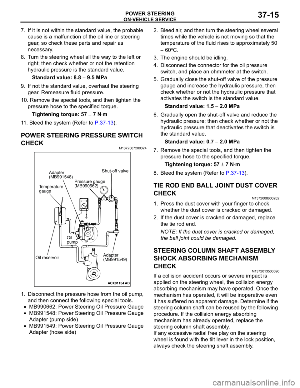
1. Disconnect the pressure hose from the oil pump,
and then connect the following special tools.
•MB990662: Power Steering Oil Pressure Gauge
•MB991548: Power Steering Oil Pressure Gauge
Adapter (pump side)
•MB991549: Power Steering Oil Pressure Gauge
Adapter (hose side)2. Bleed air, and then turn the steering wheel several
times while the vehicle is not moving so that the
temperature of the fluid rises to approximately 50
− 60°C.
3. The engine should be idling.
4. Disconnect the connector for the oil pressure
switch, and place an ohmmeter at the switch.
5. Gradually close the shut-off valve of the pressure
gauge and increase the hydraulic pressure, then
check whether or not the hydraulic pressure that
activates the switch is the standard value.
Standard value: 1.5 − 2.0 MPa
6. Gradually open the shut-off valve and reduce the
hydraulic pressure; then check whether or not the
hydraulic pressure that deactivates the switch is
the standard value.
Standard value: 0.7 − 2.0 MPa
7. Remove the special tools, and then tighten the
pressure hose to the specified torque.
Tightening torque: 57 ± 7 N⋅m
8. Bleed the system (Refer to P.37-13).
TIE ROD END BALL JOINT DUST COVER
CHECK
M1372008600262
1. Press the dust cover with your finger to check
whether the dust cover is cracked or damaged.
2. If the dust cover is cracked or damaged, replace
the tie rod end.
NOTE: If the dust cover is cracked or damaged,
the ball joint could be damaged.
STEERING COLUMN SHAFT ASSEMBLY
SHOCK ABSORBING MECHANISM
CHECK
M1372013500090
If a collision accident occurs or severe impact is
applied on the steering wheel, the collision energy
absorbing mechanism may have operated. Once the
mechanism has operated, it will be inoperative even
it has suffered no apparent damage. Determine if the
steering column shaft can be reused by the following
procedure. If the collision energy absorbing
mechanism has already operated, replace the
steering column shaft assembly.
If any excessive radial free play on the steering
wheel is found with the tilt lever in the lock position,
always check the steering shaft assembly.
ACX01134
AB
Temperature
gaugeAdapter
(MB991548)
Oil reservoirOil
pump
Adapter
(MB991549) Shut-off valve
Pressure gauge
(MB990662)
Page 250 of 788
ON-VEHICLE SERVICE
POWER STEERING37-16
WARNING
•If the vehicle continues to be driven after
the collision absorbing mechanism has
operated, the steering column shaft may
be damaged while it is in use.
•If there is a slack in the one-way capsule,
do not attempt to repair it but replace the
steering column shaft assembly.
Inspection Procedure
1. Remove the lower and upper column covers.
CAUTION
Do not release the tilt lever until the steering
column has been installed to complete this
inspection procedure.
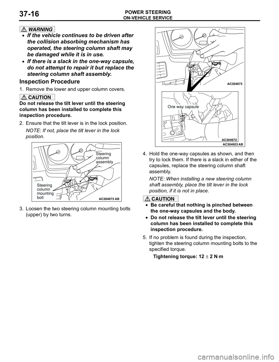
2. Ensure that the tilt lever is in the lock position.
NOTE: If not, place the tilt lever in the lock
position.
3. Loosen the two steering column mounting bolts
(upper) by two turns.4. Hold the one-way capsules as shown, and then
try to lock them. If there is a slack in either of the
capsules, replace the steering column shaft
assembly.
NOTE: When installing a new steering column
shaft assembly, place the tilt lever in the lock
position, if it is not in place.
CAUTION
•Be careful that nothing is pinched between
the one-way capsules and the body.
•Do not release the tilt lever until the steering
column has been installed to complete this
inspection procedure.
5. If no problem is found during the inspection,
tighten the steering column mounting bolts to the
specified torque.
Tightening torque: 12 ± 2 N⋅m
AC304673AC304673
Steering
column
assembly
AB
Steering
column
mounting
bolt
AC304672
AC304673AC304673
AC304923AB
One way capsule
Page 256 of 788
STEERING SHAFT
POWER STEERING37-22
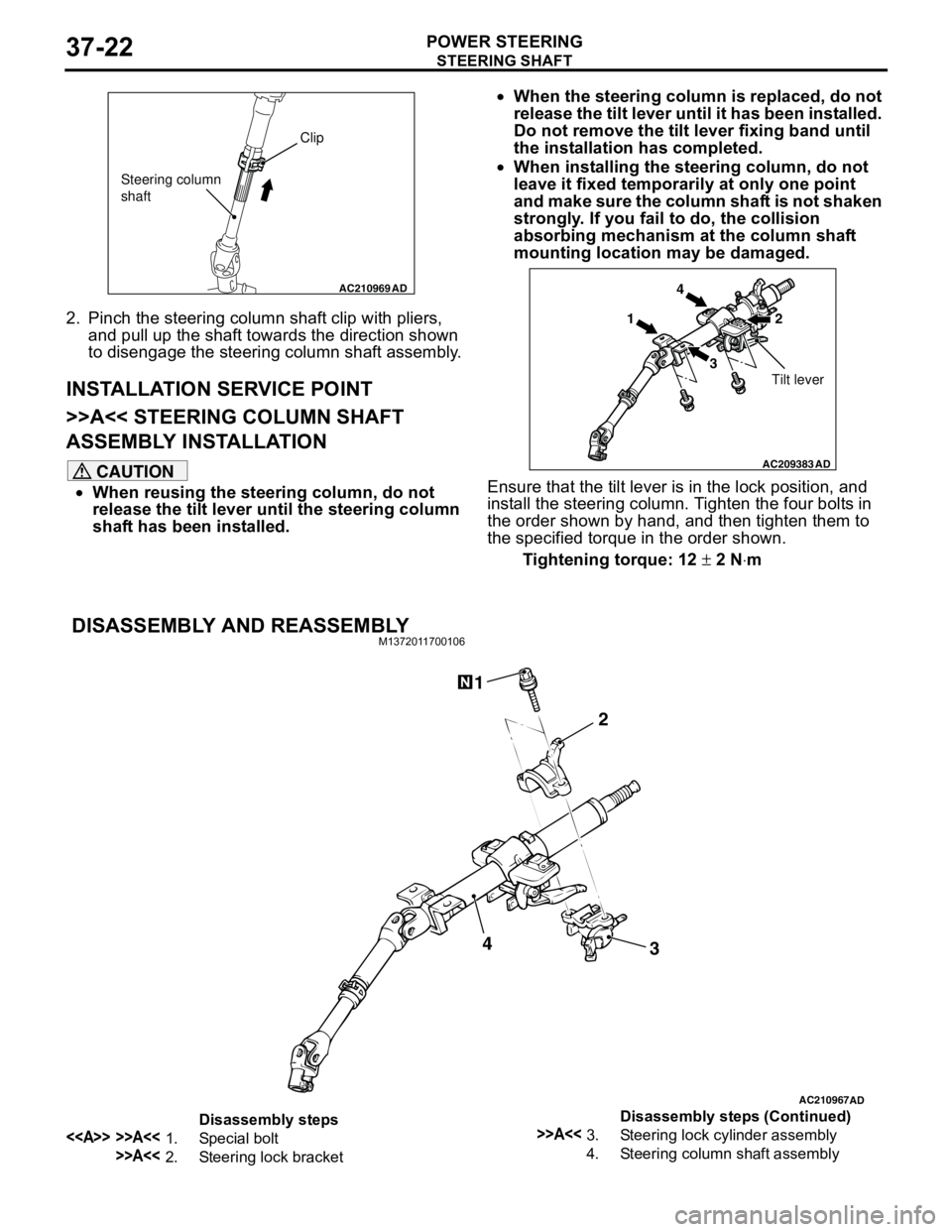
2. Pinch the steering column shaft clip with pliers,
and pull up the shaft towards the direction shown
to disengage the steering column shaft assembly.
INSTALLATION SERVICE POINT
>>A<< STEERING COLUMN SHAFT
ASSEMBLY INSTALLATION
CAUTION
•When reusing the steering column, do not
release the tilt lever until the steering column
shaft has been installed.•When the steering column is replaced, do not
release the tilt lever until it has been installed.
Do not remove the tilt lever fixing band until
the installation has completed.
•When installing the steering column, do not
leave it fixed temporarily at only one point
and make sure the column shaft is not shaken
strongly. If you fail to do, the collision
absorbing mechanism at the column shaft
mounting location may be damaged.
Ensure that the tilt lever is in the lock position, and
install the steering column. Tighten the four bolts in
the order shown by hand, and then tighten them to
the specified torque in the order shown.
Tightening torque: 12 ± 2 N⋅m
DISASSEMBLY AND REASSEMBLYM1372011700106
AC210969AD
Clip
Steering column
shaft
AC209383
AD
14
32
Tilt lever
AC210967AD
3 2 14
Disassembly steps
<> >>A<<1. Special bolt
>>A<<2. Steering lock bracket
>>A<<3. Steering lock cylinder assembly
4. Steering column shaft assemblyDisassembly steps (Continued)
Page 260 of 788
POWER STEERING GEAR BOX AND LINKAGE
POWER STEERING37-26
INSTALLATION SERVICE POINT
>>A<< JOINT COVER GROMMET
INSTALLATION
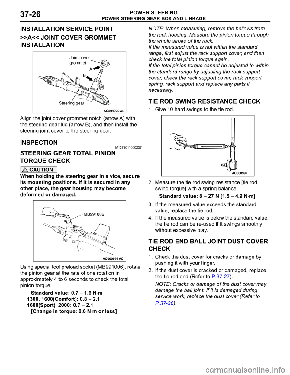
Align the joint cover grommet notch (arrow A) with
the steering gear lug (arrow B), and then install the
steering joint cover to the steering gear.
INSPECTIONM1372011000237
STEERING GEAR TOTAL PINION
TORQUE CHECK
CAUTION
When holding the steering gear in a vice, secure
its mounting positions. If it is secured in any
other place, the gear housing may become
deformed or damaged.
Using special tool preload socket (MB991006), rotate
the pinion gear at the rate of one rotation in
approximately 4 to 6 seconds to check the total
pinion torque.
Standard value: 0.7 − 1.6 N⋅m
1300, 1600(Comfort): 0.8 − 2.1
1600(Sport), 2000: 0.7 − 2.1
[Change in torque: 0.6 N⋅m or less]NOTE: When measuring, remove the bellows from
the rack housing. Measure the pinion torque through
the whole stroke of the rack.
If the measured value is not within the standard
range, first adjust the rack support cover, and then
check the total pinion torque again.
If the total pinion torque cannot be adjusted to within
the standard range by adjusting the rack support
cover, check the rack support cover, rack support
spring, rack support and replace any parts if
necessary.
TIE ROD SWING RESISTANCE CHECK
1. Give 10 hard swings to the tie rod.
2. Measure the tie rod swing resistance [tie rod
swing torque] with a spring balance.
Standard value: 8 − 27 N [1.5 − 4.9 N⋅m]
3. If the measured value exceeds the standard
value, replace the tie rod.
4. If the measured value is below the standard value,
the tie rod can be re-used if it swings smoothly
without excessive play.
TIE ROD END BALL JOINT DUST COVER
CHECK
1. Check the dust cover for cracks or damage by
pushing it with your finger.
2. If the dust cover is cracked or damaged, replace
the tie rod end (Refer to P.37-27).
NOTE: Cracks or damage of the dust cover may
damage the ball joint. If it is damaged during
service work, replace the dust cover (Refer to
P.37-36).
AC304922AB
A
B Joint cover
grommet
Steering gear
AC000996 AC
MB991006
AC000997
Page 261 of 788
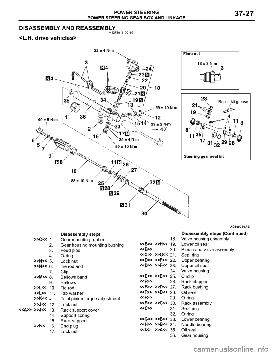
POWER STEERING GEAR BOX AND LINKAGE
POWER STEERING37-27
DISASSEMBLY AND REASSEMBLYM1372011100193
AC100244AE
3
13 ± 3 N·m
Steering gear seal kit Flare nut
Repair kit grease
23
21
19
4
11
8
28 29
32 31 17 35
11 8
22 ± 4 N·m
59 ± 10 N·m
23 ± 2 N·m
-30˚
12
14
15
33
17
59 ± 10 N·m25 ± 4 N·m
18 24
23
20
19
2122
13 344
4
3
35
136
2
16
30 31
32
27
29 28
2526 1188 ± 10 N·m
10 8
9 7 5 6
40 ± 5 N·m
Disassembly steps
>>O<<1. Gear mounting rubber
2. Gear housing mounting bushing
3. Feed pipe
4. O-ring
>>N<<5. Lock nut
>>N<<6. Tie rod end
7. Clip
>>M<<8. Bellows band
9. Bellows
>>L<<10. Tie rod
>>L<<11. Tab washer
>>K<<•Total pinion torque adjustment
>>J<<12. Lock nut
<> >>J<<13. Rack support cover
14. Support spring
15. Rack support
>>I<<16. End plug
17. Lock nut18. Valve housing assembly
<> >>H<<19. Lower oil seal
<>20. Pinion and valve assembly
<
<
<
24. Valve housing
<
<
<
<
<
<
<
32. O-ring
<
<
<> >>A<<35. Oil seal
36. Gear housingDisassembly steps (Continued)
Page 262 of 788
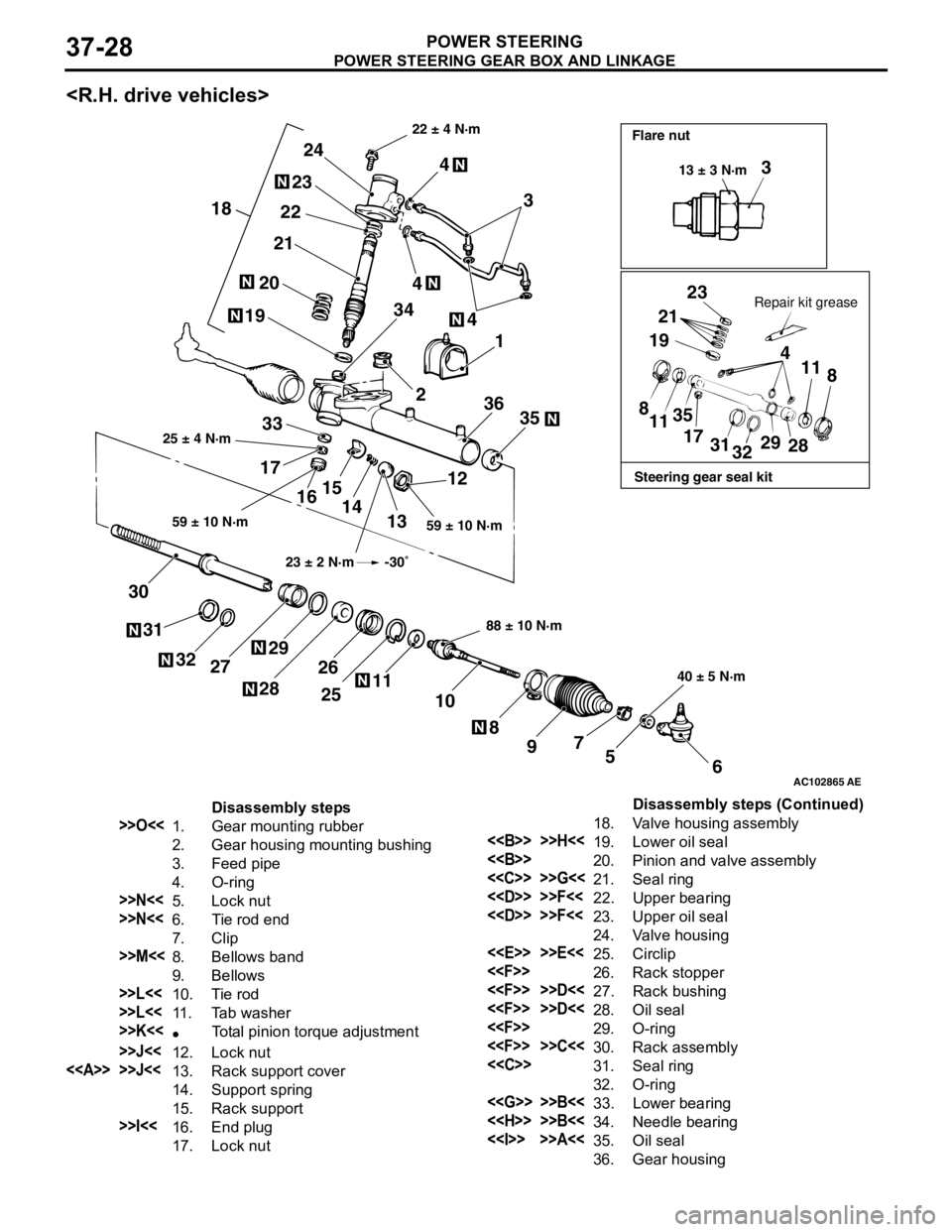
POWER STEERING GEAR BOX AND LINKAGE
POWER STEERING37-28
AC102865
3
23
21
19
4
11
8
8
1135
17
31
3229
28
6 5 7
9 8 10 11
25 26
2829
27 32 31 3012
13 14 15
16 173335 361 4
2 3444
3 24
23
22
21
20
19
18
AE
Steering gear seal kit Flare nut
Repair kit grease 22 ± 4 N·m
59 ± 10 N·m 25 ± 4 N·m
88 ± 10 N·m
40 ± 5 N·m 59 ± 10 N·m13 ± 3 N·m
23 ± 2 N·m -30˚
Disassembly steps
>>O<<1. Gear mounting rubber
2. Gear housing mounting bushing
3. Feed pipe
4. O-ring
>>N<<5. Lock nut
>>N<<6. Tie rod end
7. Clip
>>M<<8. Bellows band
9. Bellows
>>L<<10. Tie rod
>>L<<11. Tab washer
>>K<<•Total pinion torque adjustment
>>J<<12. Lock nut
<> >>J<<13. Rack support cover
14. Support spring
15. Rack support
>>I<<16. End plug
17. Lock nut18. Valve housing assembly
<> >>H<<19. Lower oil seal
<>20. Pinion and valve assembly
<
<
<
24. Valve housing
<
<
<
<
<
<
<
32. O-ring
<
<
<> >>A<<35. Oil seal
36. Gear housingDisassembly steps (Continued)