light MITSUBISHI LANCER 2005 Service Manual
[x] Cancel search | Manufacturer: MITSUBISHI, Model Year: 2005, Model line: LANCER, Model: MITSUBISHI LANCER 2005Pages: 788, PDF Size: 45.98 MB
Page 513 of 788
TROUBLESHOOTING
HEATER, AIR CONDITIONER AND VENTILATION55-29
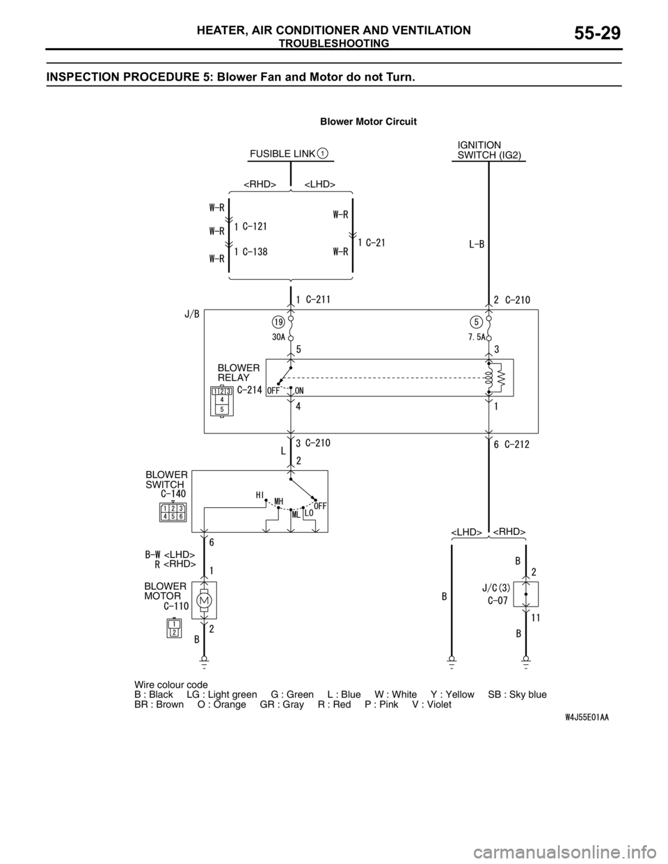
INSPECTION PROCEDURE 5: Blower Fan and Motor do not Turn.
FUSIBLE LINK1IGNITION
SWITCH (IG2)
BLOWER
RELAY
BLOWER
SWITCH
BLOWER
MOTOR
Wire colour code
B : Black LG : Light green G : Green L : Blue W : White Y : Yellow SB : Sky blue
BR : Brown O : Orange GR : Gray R : Red P : Pink V : Violet
Page 523 of 788
TROUBLESHOOTING
HEATER, AIR CONDITIONER AND VENTILATION55-39
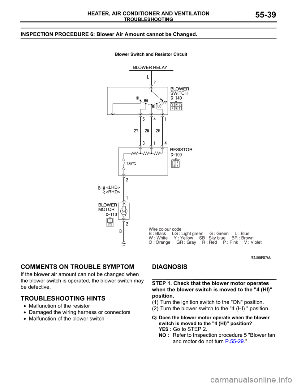
INSPECTION PROCEDURE 6: Blower Air Amount cannot be Changed.
COMMENTS ON TROUBLE SYMPTOM
If the blower air amount can not be changed when
the blower switch is operated, the blower switch may
be defective.
TROUBLESHOOTING HINTS
•Malfunction of the resistor
•Damaged the wiring harness or connectors
•Malfunction of the blower switch
DIAGNOSIS
STEP 1. Check that the blower motor operates
when the blower switch is moved to the "4 (HI)"
position.
(1) Turn the ignition switch to the "ON" position.
(2) Turn the blower switch to the "4 (HI) " position.
Q: Does the blower motor operate when the blower
switch is moved to the "4 (HI)" position?
YES :
Go to STEP 2.
NO : Refer to Inspection procedure 5 "Blower fan
and motor do not turn P.55-29."
BLOWER RELAY
BLOWER
SWITCH
RESISTOR
BLOWER
MOTOR
Wire colour code
B : Black LG : Light green G : Green L : Blue
W : White Y : Yellow SB : Sky blue BR : Brown
O : Orange GR : Gray R : Red P : Pink V : Violet
Page 526 of 788
TROUBLESHOOTING
HEATER, AIR CONDITIONER AND VENTILATION55-42
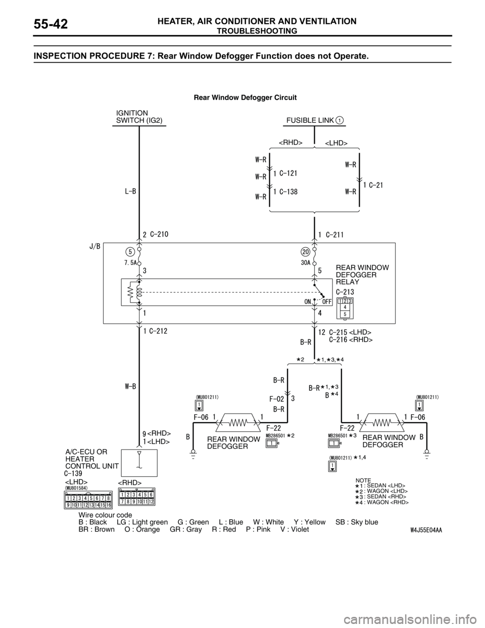
INSPECTION PROCEDURE 7: Rear Window Defogger Function does not Operate.
IGNITION
SWITCH (IG2) FUSIBLE LINK
REAR WINDOW
DEFOGGER
RELAY
A/C-ECU OR
HEATER
CONTROL UNIT1
: SEDAN
: WAGON
: SEDAN
: WAGON
Wire colour code
B : Black LG : Light green G : Green L : Blue W : White Y : Yellow SB : Sky blue
BR : Brown O : Orange GR : Gray R : Red P : Pink V : Violet
NOTE
REAR WINDOW
DEFOGGERREAR WINDOW
DEFOGGER Rear Window Defogger Circuit
Page 537 of 788
TROUBLESHOOTING
HEATER, AIR CONDITIONER AND VENTILATION55-53
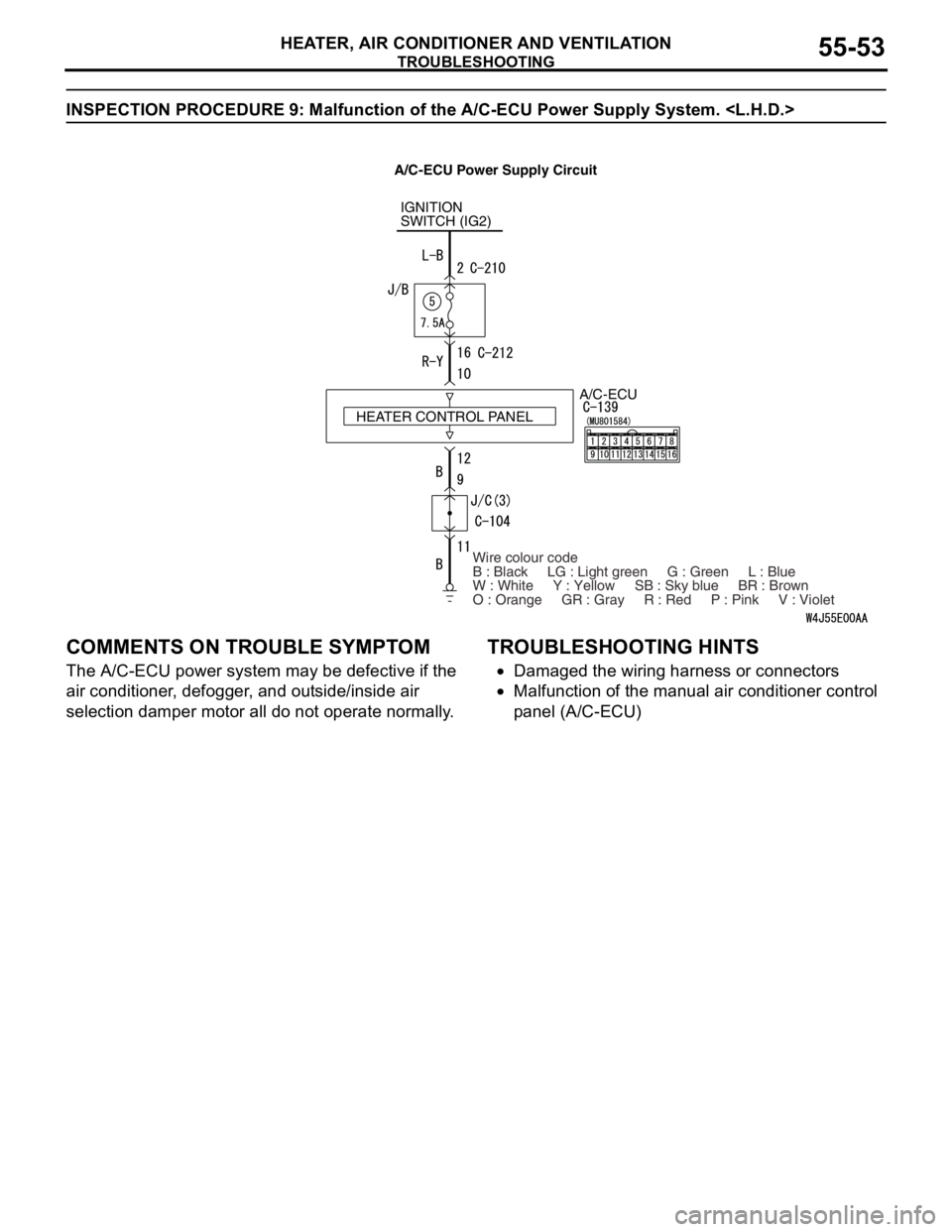
INSPECTION PROCEDURE 9: Malfunction of the A/C-ECU Power Supply System.
COMMENTS ON TROUBLE SYMPTOM
The A/C-ECU power system may be defective if the
air conditioner, defogger, and outside/inside air
selection damper motor all do not operate normally.
TROUBLESHOOTING HINTS
•Damaged the wiring harness or connectors
•Malfunction of the manual air conditioner control
panel (A/C-ECU)
IGNITION
SWITCH (IG2)
A/C-ECU
Wire colour code
B : Black LG : Light green G : Green L : Blue
W : White Y : Yellow SB : Sky blue BR : Brown
O : Orange GR : Gray R : Red P : Pink V : Violet HEATER CONTROL PANEL
A/C-ECU Power Supply Circuit
Page 540 of 788
TROUBLESHOOTING
HEATER, AIR CONDITIONER AND VENTILATION55-56
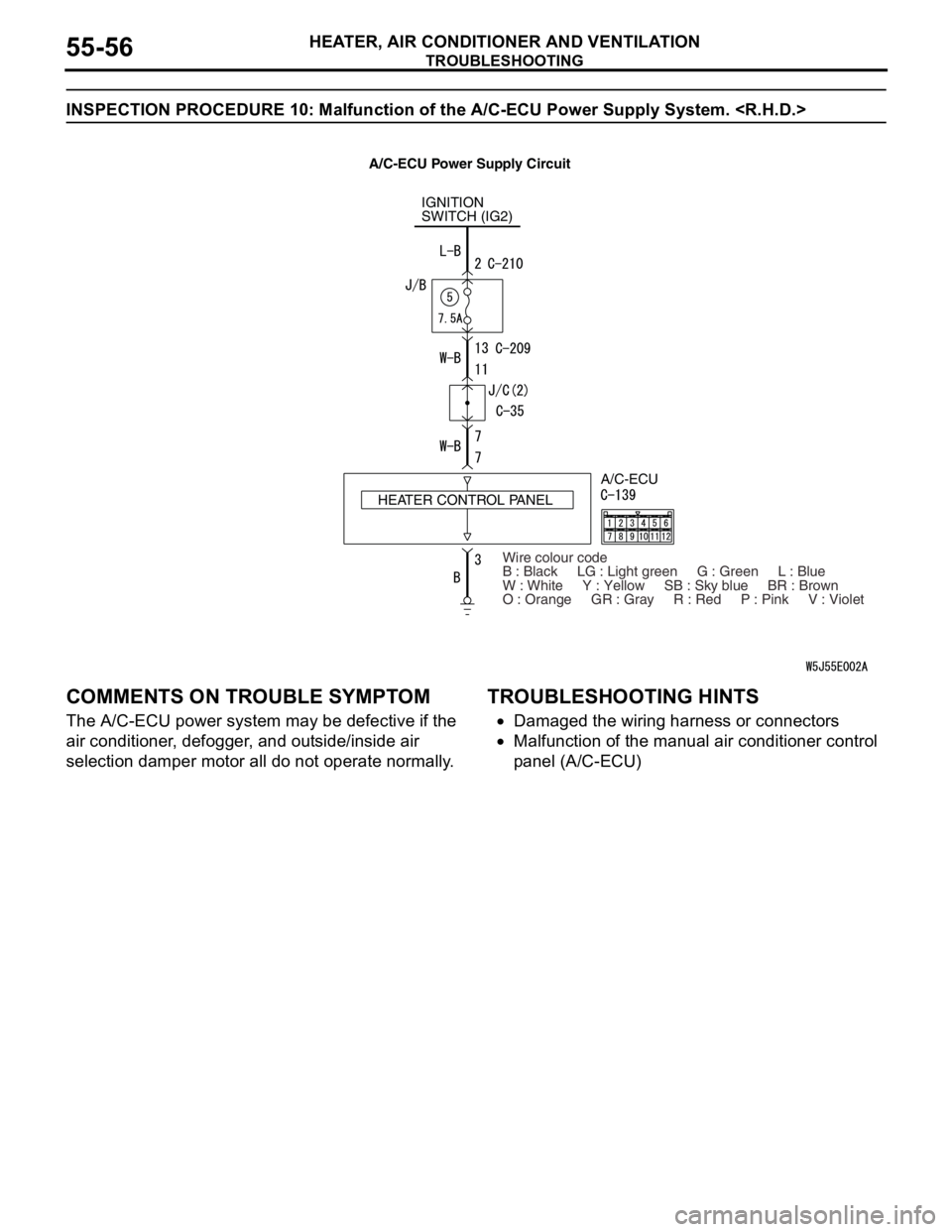
INSPECTION PROCEDURE 10: Malfunction of the A/C-ECU Power Supply System.
COMMENTS ON TROUBLE SYMPTOM
The A/C-ECU power system may be defective if the
air conditioner, defogger, and outside/inside air
selection damper motor all do not operate normally.
TROUBLESHOOTING HINTS
•Damaged the wiring harness or connectors
•Malfunction of the manual air conditioner control
panel (A/C-ECU)
IGNITION
SWITCH (IG2)
HEATER CONTROL PANELA/C-ECU
Wire colour code
B : Black LG : Light green G : Green L : Blue
W : White Y : Yellow SB : Sky blue BR : Brown
O : Orange GR : Gray R : Red P : Pink V : Violet
A/C-ECU Power Supply Circuit
Page 543 of 788
TROUBLESHOOTING
HEATER, AIR CONDITIONER AND VENTILATION55-59
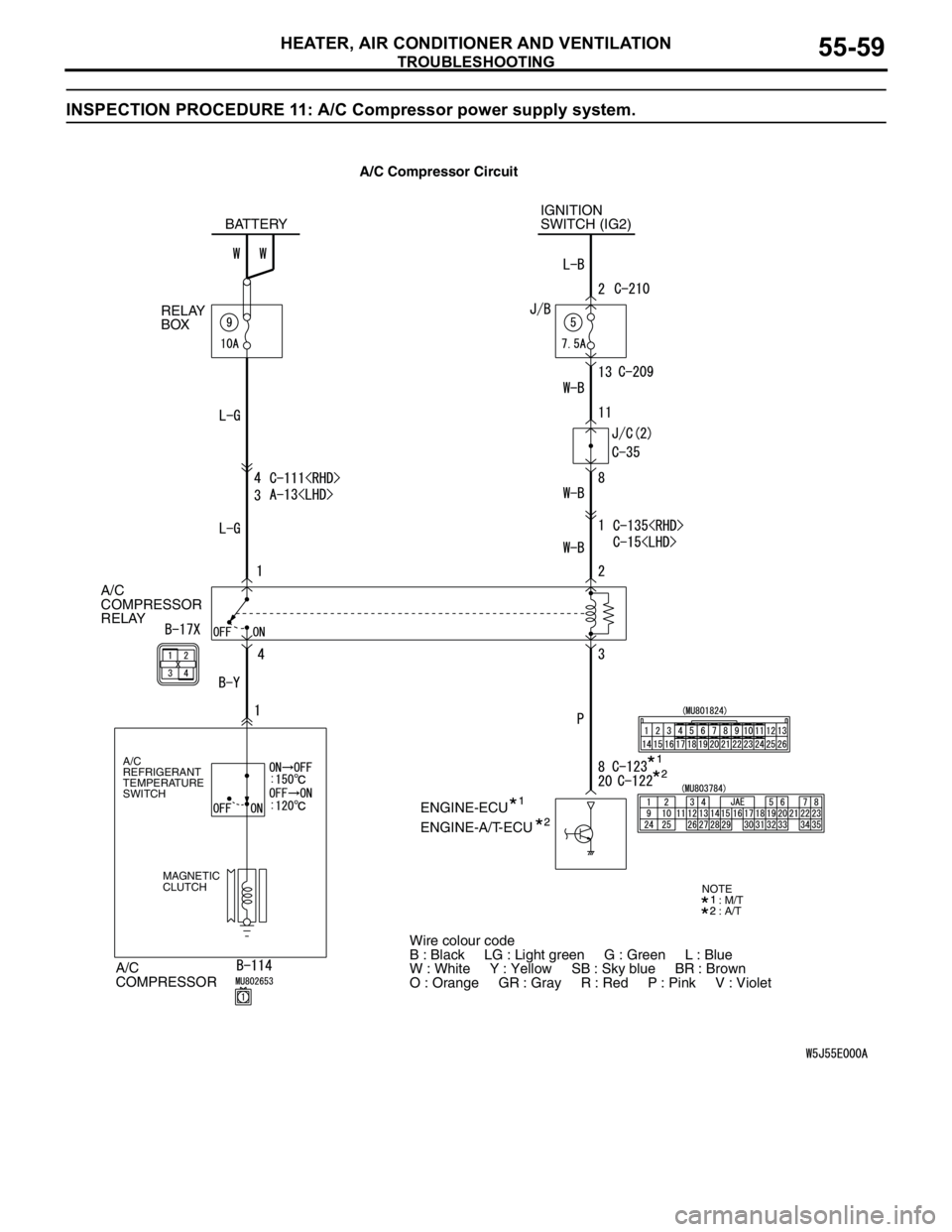
INSPECTION PROCEDURE 11: A/C Compressor power supply system.
A/C
COMPRESSOR
RELAY
A/C
COMPRESSOR
A/C
REFRIGERANT
TEMPERATURE
SWITCH
MAGNETIC
CLUTCH
IGNITION
SWITCH (IG2)
ENGINE-ECU BATTERY
RELAY
BOX
ENGINE-A/T-ECU
Wire colour code
B : Black LG : Light green G : Green L : Blue
W : White Y : Yellow SB : Sky blue BR : Brown
O : Orange GR : Gray R : Red P : Pink V : Violet
: M/T
: A/TNOTE
A/C Compressor Circuit
Page 551 of 788

TROUBLESHOOTING
HEATER, AIR CONDITIONER AND VENTILATION55-67
CHECK AT ECU TERMINAL
12
345
678
9 10111213141516
AC300861AC
Terminal No. Check item Checking requirement Normal condition
1 Rear defogger switch Defogger switch: ON 0 V
Defogger switch: OFF System voltage
2 Inside/outside air selection
damper motor (outside air)When the damper is moved to
the inside air recirculation
position0 V
When the damper is moved to
the outside air inside air intake
positionSystem voltage
3 Inside/outside air selection
damper motor (inside air)When the damper is moved to
the inside air recirculation
positionSystem voltage
When the damper is moved to
the outside air inside air intake
position0 V
4 Output to the engine-A/T-ECU
(A/C1)A/C stopped 0 V
•A/C switch: ON
•Blower switch: ONSystem voltage
5 Output to the engine-A/T-ECU
(A/C2)When the A/C is under low load System voltage
When the A/C is under high
load0 V
6 Power supply to the A/C
illuminationLighting switch: ON System voltage
7---
8 Blower switch (lo) blower switch: lo System voltage
9---
10 Power supply to the ignition
switch (IG2)Ignition switch: ON System voltage
11 Earth to the A/C illumination Always 0 V
12 Earth Always 0 V
13 Air thermo sensor (outlet side) Sensor probe temperature 25°C
(1.5k ohm)2.2 V
14, 15 - - -
16 Earth to the air thermo sensor Always 0 V
Page 552 of 788

TROUBLESHOOTING
HEATER, AIR CONDITIONER AND VENTILATION55-68
CHECK AT ECU TERMINAL
21
78
6 534
11
10912
AC304990
AB
Terminal No. Check item Checking requirement Normal condition
1 Output to the engine-A/T-ECU
(A/C1)A/C stopped 0 V
•A/C switch: ON
•Blower switch: ONSystem voltage
2 Output to the engine-A/T-ECU
(A/C2)When the A/C is under low load System voltage
When the A/C is under high
load0 V
3 Earth Always 0 V
4 Earth to the air thermo sensor Always 0 V
5 Power supply to the A/C
illuminationLighting switch: ON System voltage
6 Air thermo sensor (outlet side) Sensor probe temperature 25°C
(1.5k ohm)2.2 V
7 Power supply to the ignition
switch (IG2)Ignition switch: ON System voltage
8 Blower switch (lo) blower switch: lo System voltage
9 Rear defogger switch Defogger switch: ON 0 V
Defogger switch: OFF System voltage
10 Inside/outside air selection
damper motor (outside air)When the damper is moved to
the inside air recirculation
position0 V
When the damper is moved to
the outside air inside air intake
positionSystem voltage
11 Inside/outside air selection
damper motor (inside air)When the damper is moved to
the inside air recirculation
positionSystem voltage
When the damper is moved to
the outside air inside air intake
position0 V
12 Earth to the A/C illumination Always 0 V
Page 557 of 788
ON-VEHICLE SERVICE
HEATER, AIR CONDITIONER AND VENTILATION55-73
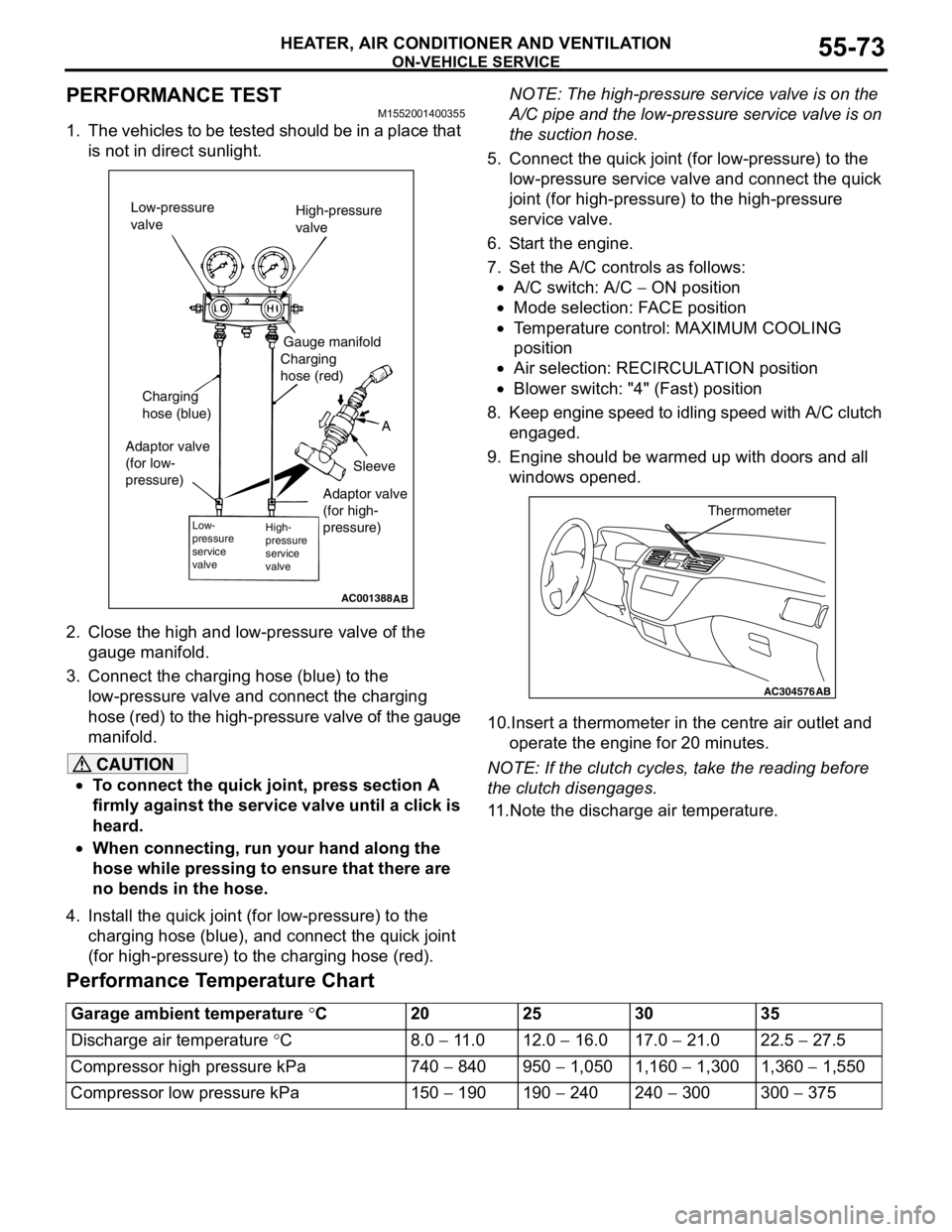
PERFORMANCE TEST M1552001400355
1. The vehicles to be tested should be in a place that
is not in direct sunlight.
2. Close the high and low-pressure valve of the
gauge manifold.
3. Connect the charging hose (blue) to the
low-pressure valve and connect the charging
hose (red) to the high-pressure valve of the gauge
manifold.
CAUTION
•To connect the quick joint, press section A
firmly against the service valve until a click is
heard.
•When connecting, run your hand along the
hose while pressing to ensure that there are
no bends in the hose.
4. Install the quick joint (for low-pressure) to the
charging hose (blue), and connect the quick joint
(for high-pressure) to the charging hose (red).NOTE: The high-pressure service valve is on the
A/C pipe and the low-pressure service valve is on
the suction hose.
5. Connect the quick joint (for low-pressure) to the
low-pressure service valve and connect the quick
joint (for high-pressure) to the high-pressure
service valve.
6. Start the engine.
7. Set the A/C controls as follows:
•A/C switch: A/C − ON position
•Mode selection: FACE position
•Temperature control: MAXIMUM COOLING
position
•Air selection: RECIRCULATION position
•Blower switch: "4" (Fast) position
8. Keep engine speed to idling speed with A/C clutch
engaged.
9. Engine should be warmed up with doors and all
windows opened.
10.Insert a thermometer in the centre air outlet and
operate the engine for 20 minutes.
NOTE: If the clutch cycles, take the reading before
the clutch disengages.
11.Note the discharge air temperature.
Performance Temperature Chart
AC001388
Low-pressure
valveHigh-pressure
valve
Gauge manifold
Charging
hose (red)
A
Sleeve Charging
hose (blue)
Adaptor valve
(for low-
pressure)
Low-
pressure
service
valveHigh-
pressure
service
valve
AB
Adaptor valve
(for high-
pressure)
AC304576
Thermometer
AB
Garage ambient temperature °C20 25 30 35
Discharge air temperature °C8.0 − 11.0 12.0 − 16.0 17.0 − 21.0 22.5 − 27.5
Compressor high pressure kPa 740 − 840 950 − 1,050 1,160 − 1,300 1,360 − 1,550
Compressor low pressure kPa 150 − 190 190 − 240 240 − 300 300 − 375
Page 579 of 788
COMPRESSOR ASSEMBLY AND TENSION PULLEY
HEATER, AIR CONDITIONER AND VENTILATION55-95
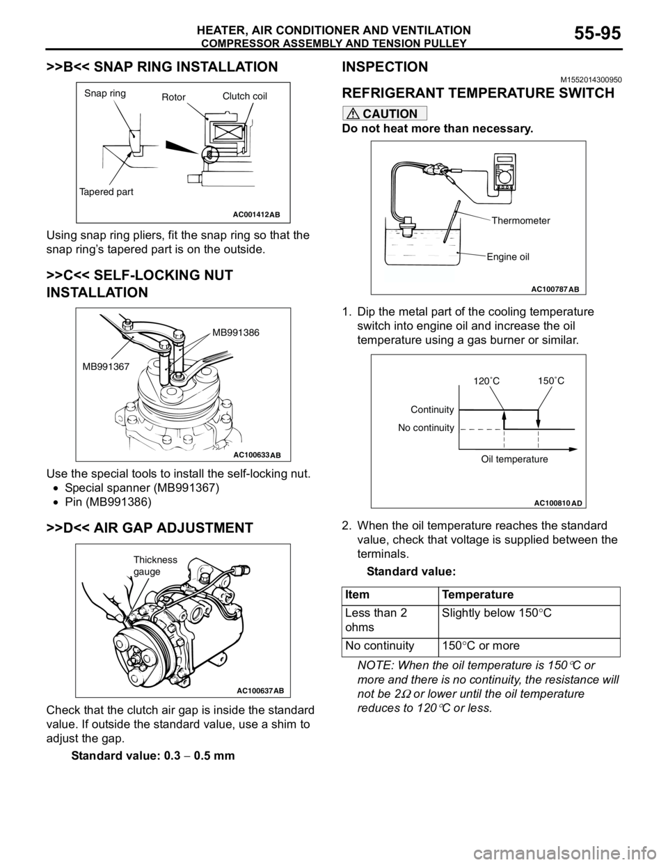
>>B<< SNAP RING INSTALLATION
Using snap ring pliers, fit the snap ring so that the
snap ring’s tapered part is on the outside.
>>C<< SELF-LOCKING NUT
INSTALLATION
Use the special tools to install the self-locking nut.
•Special spanner (MB991367)
•Pin (MB991386)
>>D<< AIR GAP ADJUSTMENT
Check that the clutch air gap is inside the standard
value. If outside the standard value, use a shim to
adjust the gap.
Standard value: 0.3 − 0.5 mm
INSPECTIONM1552014300950
REFRIGERANT TEMPERATURE SWITCH
CAUTION
Do not heat more than necessary.
1. Dip the metal part of the cooling temperature
switch into engine oil and increase the oil
temperature using a gas burner or similar.
2. When the oil temperature reaches the standard
value, check that voltage is supplied between the
terminals.
Standard value:
NOTE: When the oil temperature is 150
°C or
more and there is no continuity, the resistance will
not be 2
Ω or lower until the oil temperature
reduces to 120
°C or less.
AC001412
Snap ring
RotorClutch coil
Tapered part
AB
AC100633AB
MB991386
MB991367
AC100637AB
Thickness
gauge
Item Temperature
Less than 2
ohmsSlightly below 150°C
No continuity 150°C or more
AC100787
Thermometer
Engine oil
AB
AC100810
Continuity
No continuity
Oil temperature
AD
120˚C150˚C