light MITSUBISHI LANCER 2005 Owner's Manual
[x] Cancel search | Manufacturer: MITSUBISHI, Model Year: 2005, Model line: LANCER, Model: MITSUBISHI LANCER 2005Pages: 788, PDF Size: 45.98 MB
Page 389 of 788
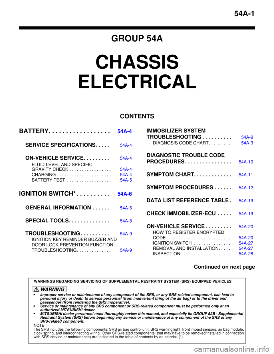
54A-1
GROUP 54A
CHASSIS
ELECTRICAL
CONTENTS
BATTERY. . . . . . . . . . . . . . . . . .
54A-4
SERVICE SPECIFICATIONS. . . . .
54A-4
ON-VEHICLE SERVICE. . . . . . . . .54A-4
FLUID LEVEL AND SPECIFIC
GRAVITY CHECK . . . . . . . . . . . . . . . . . 54A-4
CHARGING . . . . . . . . . . . . . . . . . . . . . . 54A-4
BATTERY TEST . . . . . . . . . . . . . . . . . . 54A-5
IGNITION SWITCH* . . . . . . . . . .54A-6
GENERAL INFORMATION . . . . . .
54A-6
SPECIAL TOOLS. . . . . . . . . . . . . .54A-8
TROUBLESHOOTING . . . . . . . . . .54A-9
IGNITION KEY REMINDER BUZZER AND
DOOR LOCK PREVENTION FUNCTION
TROUBLESHOOTING . . . . . . . . . . . . . . 54A-9
IMMOBILIZER SYSTEM
TROUBLESHOOTING . . . . . . . . . .
54A-9
DIAGNOSIS CODE CHART . . . . . . . . . . 54A-9
DIAGNOSTIC TROUBLE CODE
PROCEDURES . . . . . . . . . . . . . . . .
54A-10
SYMPTOM CHART. . . . . . . . . . . . .54A-11
SYMPTOM PROCEDURES . . . . . .54A-12
DATA LIST REFERENCE TABLE .54A-19
CHECK IMMOBILIZER-ECU . . . . .54A-19
ON-VEHICLE SERVICE . . . . . . . . .54A-20
HOW TO REGISTER ENCRYPTED
CODE . . . . . . . . . . . . . . . . . . . . . . . . . . . 54A-20
IGNITION SWITCH . . . . . . . . . . . . . . . . 54A-27
REMOVAL AND INSTALLATION . . . . . . 54A-27
INSPECTION . . . . . . . . . . . . . . . . . . . . . 54A-28
Continued on next page
WARNINGS REGARDING SERVICING OF SUPPLEMENTAL RESTRAINT SYSTEM (SRS) EQUIPPED VEHICLES
WARNING
•Improper service or maintenance of any component of the SRS, or any SRS-related component, can lead to
personal injury or death to service personnel (from inadvertent firing of the air bag) or to the driver and
paassenger (from rendering the SRS inoperative).
•Service or maintenance of any SRS component or SRS-related component must be performed only at an
authorized MITSUBISHI dealer.
•MITSUBISHI dealer personnel must thoroughly review this manual, and especially its GROUP 52B - Supplemental
Restraint System (SRS) before beginning any service or maintenance of any component of the SRS or any
SRS-related component.
NOTE
The SRS includes the following components: SRS air bag control unit, SRS warning light, front impact sensors, air bag module,
clock spring, and interconnecting wiring. Other SRS-related components (that may have to be removed/installed in connection
with SRS service or maintenance) are indicated in the table of contents by an asterisk (*).
Page 391 of 788
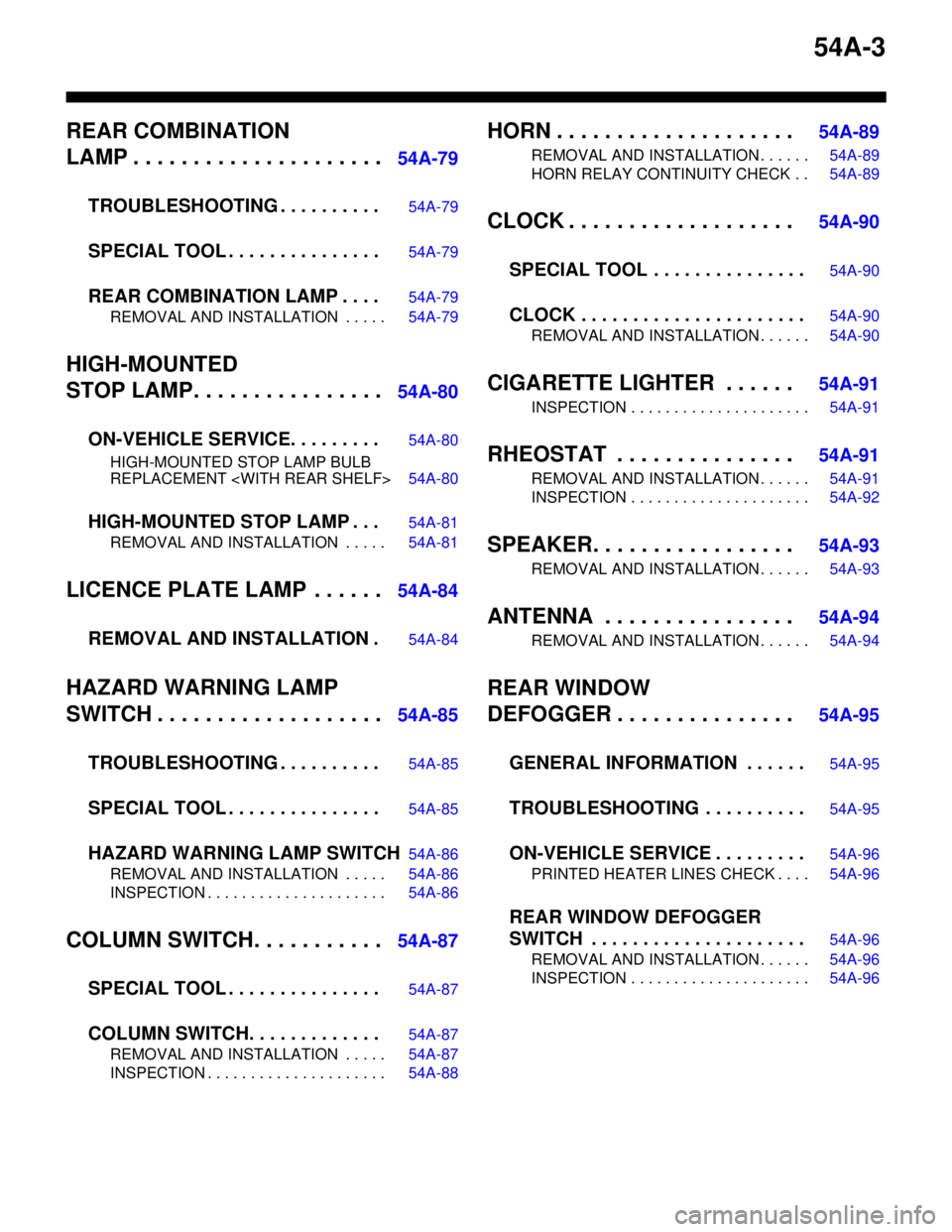
54A-3
REAR COMBINATION
LAMP . . . . . . . . . . . . . . . . . . . . .
54A-79
TROUBLESHOOTING . . . . . . . . . .
54A-79
SPECIAL TOOL . . . . . . . . . . . . . . .54A-79
REAR COMBINATION LAMP . . . .54A-79
REMOVAL AND INSTALLATION . . . . . 54A-79
HIGH-MOUNTED
STOP LAMP. . . . . . . . . . . . . . . .
54A-80
ON-VEHICLE SERVICE. . . . . . . . .
54A-80
HIGH-MOUNTED STOP LAMP BULB
REPLACEMENT
HIGH-MOUNTED STOP LAMP . . .54A-81
REMOVAL AND INSTALLATION . . . . . 54A-81
LICENCE PLATE LAMP . . . . . .54A-84
REMOVAL AND INSTALLATION .
54A-84
HAZARD WARNING LAMP
SWITCH . . . . . . . . . . . . . . . . . . .
54A-85
TROUBLESHOOTING . . . . . . . . . .
54A-85
SPECIAL TOOL . . . . . . . . . . . . . . .54A-85
HAZARD WARNING LAMP SWITCH54A-86
REMOVAL AND INSTALLATION . . . . . 54A-86
INSPECTION . . . . . . . . . . . . . . . . . . . . . 54A-86
COLUMN SWITCH. . . . . . . . . . .54A-87
SPECIAL TOOL . . . . . . . . . . . . . . .
54A-87
COLUMN SWITCH. . . . . . . . . . . . .54A-87
REMOVAL AND INSTALLATION . . . . . 54A-87
INSPECTION . . . . . . . . . . . . . . . . . . . . . 54A-88
HORN . . . . . . . . . . . . . . . . . . . . 54A-89
REMOVAL AND INSTALLATION . . . . . . 54A-89
HORN RELAY CONTINUITY CHECK . . 54A-89
CLOCK . . . . . . . . . . . . . . . . . . . 54A-90
SPECIAL TOOL . . . . . . . . . . . . . . .
54A-90
CLOCK . . . . . . . . . . . . . . . . . . . . . .54A-90
REMOVAL AND INSTALLATION . . . . . . 54A-90
CIGARETTE LIGHTER . . . . . . 54A-91
INSPECTION . . . . . . . . . . . . . . . . . . . . . 54A-91
RHEOSTAT . . . . . . . . . . . . . . . 54A-91
REMOVAL AND INSTALLATION . . . . . . 54A-91
INSPECTION . . . . . . . . . . . . . . . . . . . . . 54A-92
SPEAKER. . . . . . . . . . . . . . . . . 54A-93
REMOVAL AND INSTALLATION . . . . . . 54A-93
ANTENNA . . . . . . . . . . . . . . . . 54A-94
REMOVAL AND INSTALLATION . . . . . . 54A-94
REAR WINDOW
DEFOGGER . . . . . . . . . . . . . . .
54A-95
GENERAL INFORMATION . . . . . .
54A-95
TROUBLESHOOTING . . . . . . . . . .54A-95
ON-VEHICLE SERVICE . . . . . . . . .54A-96
PRINTED HEATER LINES CHECK . . . . 54A-96
REAR WINDOW DEFOGGER
SWITCH . . . . . . . . . . . . . . . . . . . . .
54A-96
REMOVAL AND INSTALLATION . . . . . . 54A-96
INSPECTION . . . . . . . . . . . . . . . . . . . . . 54A-96
Page 400 of 788
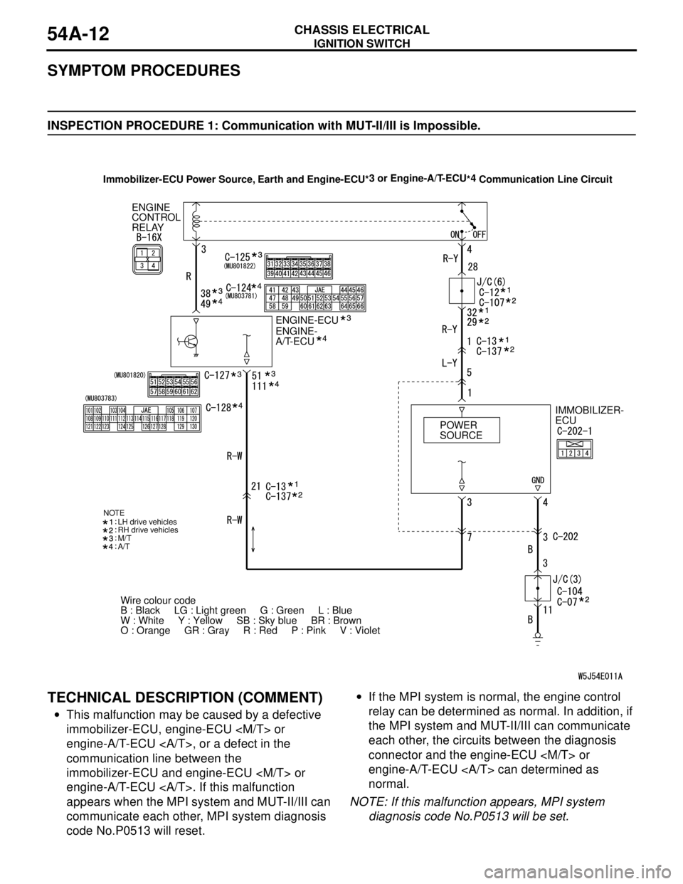
IGNITION SWITCH
CHASSIS ELECTRICAL54A-12
SYMPTOM PROCEDURES
INSPECTION PROCEDURE 1: Communication with MUT-II/III is Impossible.
TECHNICAL DESCRIPTION (COMMENT)
•This malfunction may be caused by a defective
immobilizer-ECU, engine-ECU
engine-A/T-ECU , or a defect in the
communication line between the
immobilizer-ECU and engine-ECU
engine-A/T-ECU . If this malfunction
appears when the MPI system and MUT-II/III can
communicate each other, MPI system diagnosis
code No.P0513 will reset.•If the MPI system is normal, the engine control
relay can be determined as normal. In addition, if
the MPI system and MUT-II/III can communicate
each other, the circuits between the diagnosis
connector and the engine-ECU
engine-A/T-ECU can determined as
normal.
NOTE: If this malfunction appears, MPI system
diagnosis code No.P0513 will be set.
ENGINE-ECU ENGINE
CONTROL
RELAY
ENGINE-
A/T-ECU
IMMOBILIZER-
ECU
Wire colour code
B : Black LG : Light green G : Green L : Blue
W : White Y : Yellow SB : Sky blue BR : Brown
O : Orange GR : Gray R : Red P : Pink V : Violet POWER
SOURCE
M/T
A/T NOTE
LH drive vehicles
RH drive vehicles
Immobilizer-ECU Power Source, Earth and Engine-ECU*3 or Engine-A/T-ECU
*4
Communication Line Circuit
Page 420 of 788
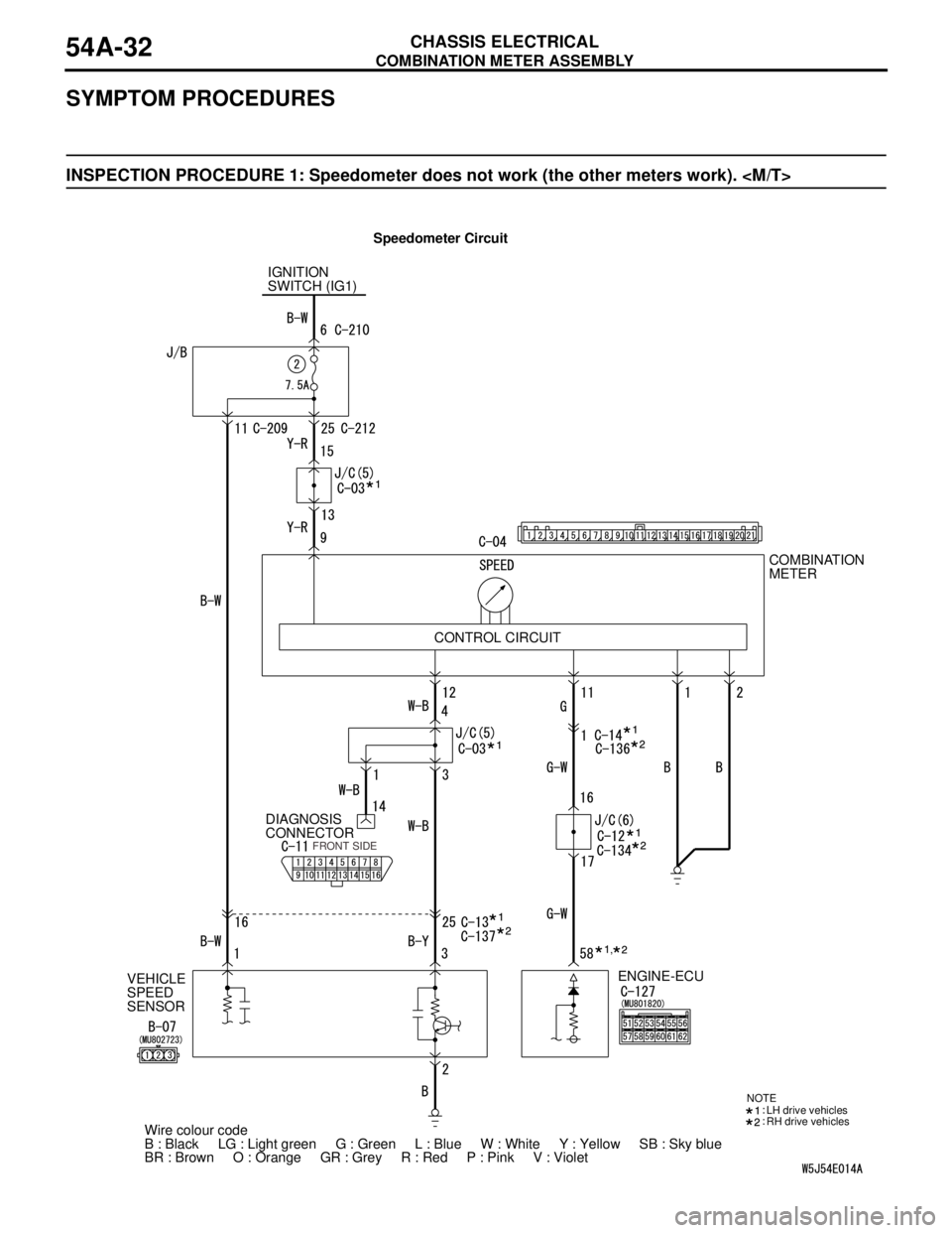
COMBINATION METER ASSEMBLY
CHASSIS ELECTRICAL54A-32
SYMPTOM PROCEDURES
INSPECTION PROCEDURE 1: Speedometer does not work (the other meters work).
Speedometer Circuit
IGNITION
SWITCH (IG1)
VEHICLE
SPEED
SENSORDIAGNOSIS
CONNECTORCOMBINATION
METER
ENGINE-ECU
Wire colour code
B : Black LG : Light green G : Green L : Blue W : White Y : Yellow SB : Sky blue
BR : Brown O : Orange GR : Grey R : Red P : Pink V : Violet CONTROL CIRCUIT
FRONT SIDE
NOTE
LH drive vehicles
RH drive vehicles
,
Page 425 of 788
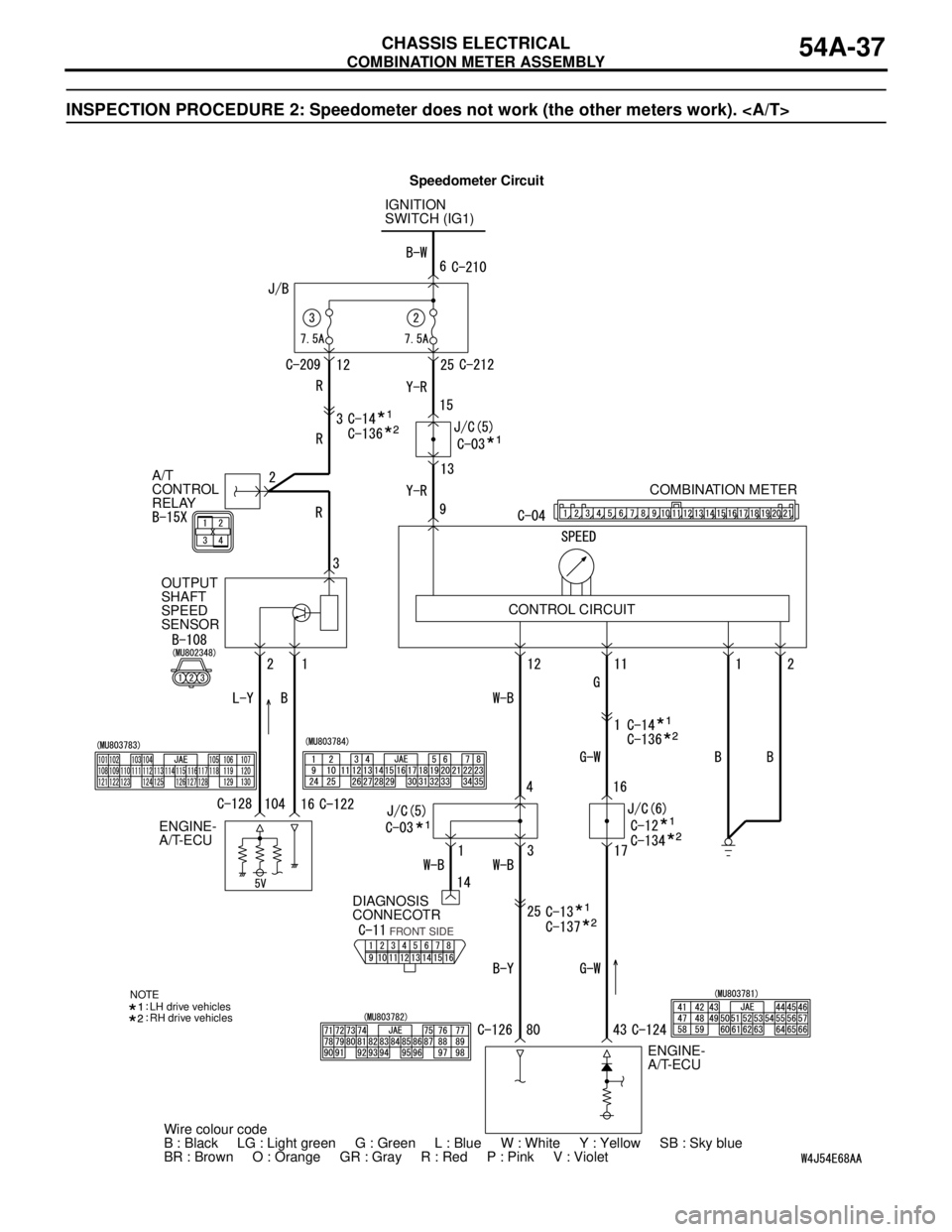
COMBINATION METER ASSEMBLY
CHASSIS ELECTRICAL54A-37
INSPECTION PROCEDURE 2: Speedometer does not work (the other meters work).
IGNITION
SWITCH (IG1)
A/T
CONTROL
RELAY
OUTPUT
SHAFT
SPEED
SENSOR
DIAGNOSIS
CONNECOTR
ENGINE-
A/T-ECUCOMBINATION METER
ENGINE-
A/T-ECU
Wire colour code
B : Black LG : Light green G : Green L : Blue W : White Y : Yellow SB : Sky blue
BR : Brown O : Orange GR : Gray R : Red P : Pink V : Violet
FRONT SIDE
NOTE
LH drive vehicles
RH drive vehicles
CONTROL CIRCUIT
Speedometer Circuit
Page 432 of 788
COMBINATION METER ASSEMBLY
CHASSIS ELECTRICAL54A-44
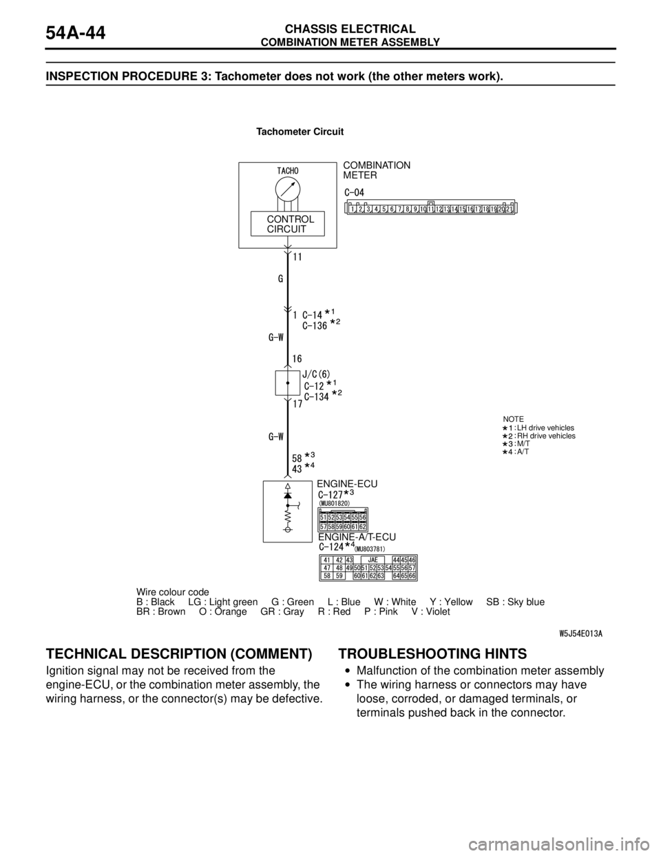
INSPECTION PROCEDURE 3: Tachometer does not work (the other meters work).
TECHNICAL DESCRIPTION (COMMENT)
Ignition signal may not be received from the
engine-ECU, or the combination meter assembly, the
wiring harness, or the connector(s) may be defective.
TROUBLESHOOTING HINTS
•Malfunction of the combination meter assembly
•The wiring harness or connectors may have
loose, corroded, or damaged terminals, or
terminals pushed back in the connector.
ENGINE-ECU
Wire colour code
B : Black LG : Light green G : Green L : Blue W : White Y : Yellow SB : Sky blue
BR : Brown O : Orange GR : Gray R : Red P : Pink V : Violet ENGINE-A/T-ECU
M/T
A/T
NOTELH drive vehicles
RH drive vehicles
COMBINATION
METER
CONTROL
CIRCUIT
Tachometer Circuit
Page 436 of 788
COMBINATION METER ASSEMBLY
CHASSIS ELECTRICAL54A-48
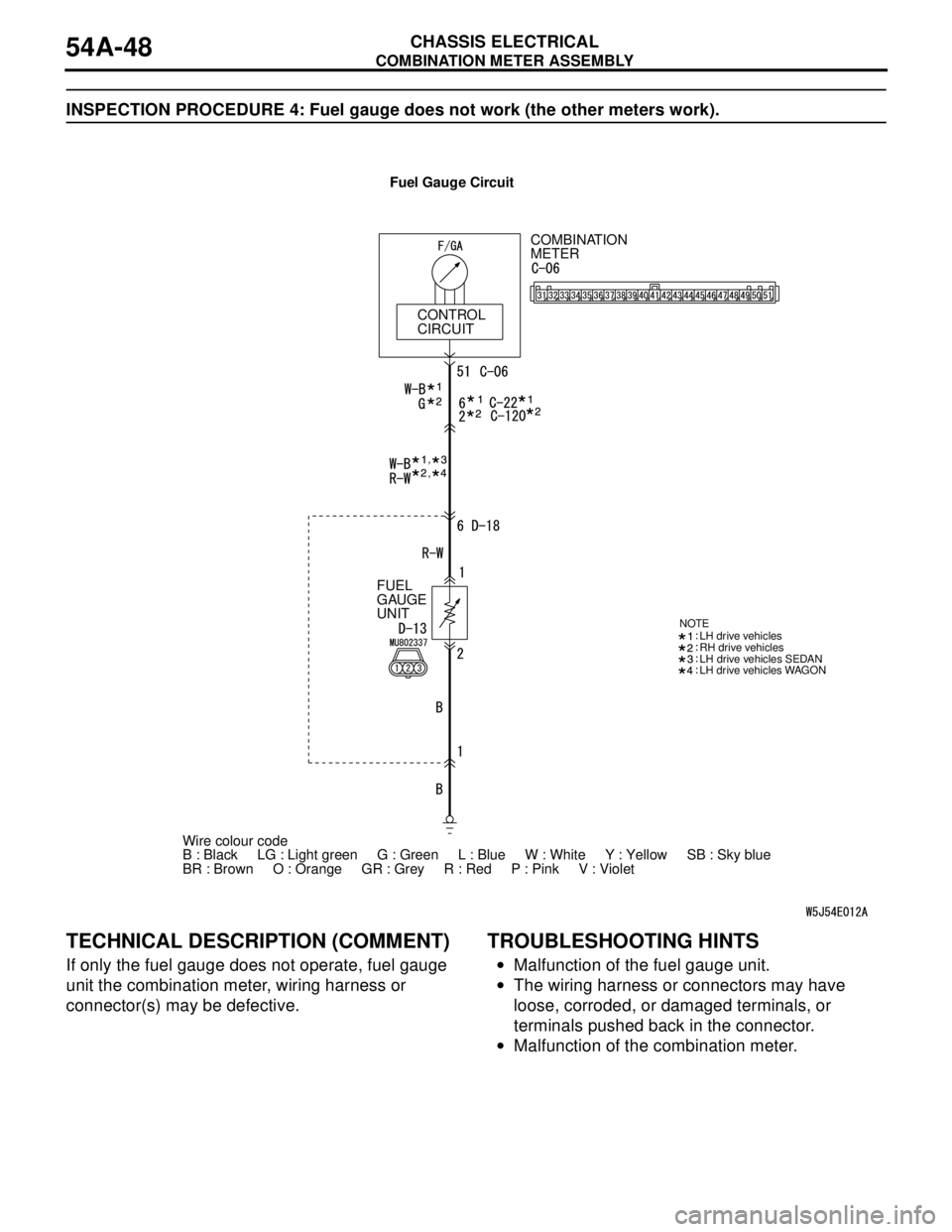
INSPECTION PROCEDURE 4: Fuel gauge does not work (the other meters work).
TECHNICAL DESCRIPTION (COMMENT)
If only the fuel gauge does not operate, fuel gauge
unit the combination meter, wiring harness or
connector(s) may be defective.
TROUBLESHOOTING HINTS
•Malfunction of the fuel gauge unit.
•The wiring harness or connectors may have
loose, corroded, or damaged terminals, or
terminals pushed back in the connector.
•Malfunction of the combination meter.
COMBINATION
METER
CONTROL
CIRCUIT
FUEL
GAUGE
UNIT
LH drive vehicles SEDAN
LH drive vehicles WAGON NOTE
LH drive vehicles
RH drive vehicles
,,
Wire colour code
B : Black LG : Light green G : Green L : Blue W : White Y : Yellow SB : Sky blue
BR : Brown O : Orange GR : Grey R : Red P : Pink V : VioletFuel Gauge Circuit
Page 439 of 788
COMBINATION METER ASSEMBLY
CHASSIS ELECTRICAL54A-51
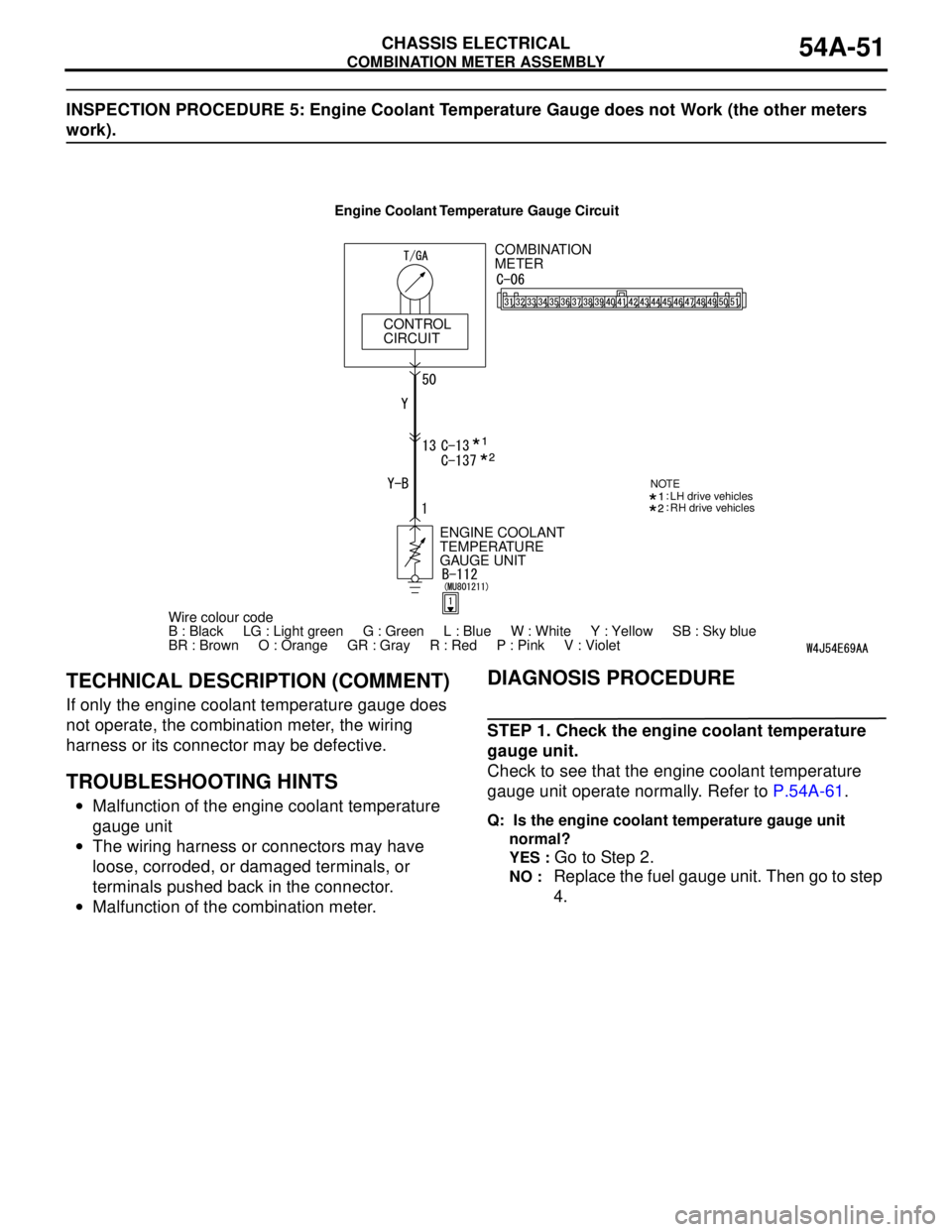
INSPECTION PROCEDURE 5: Engine Coolant Temperature Gauge does not Work (the other meters
work).
TECHNICAL DESCRIPTION (COMMENT)
If only the engine coolant temperature gauge does
not operate, the combination meter, the wiring
harness or its connector may be defective.
TROUBLESHOOTING HINTS
•Malfunction of the engine coolant temperature
gauge unit
•The wiring harness or connectors may have
loose, corroded, or damaged terminals, or
terminals pushed back in the connector.
•Malfunction of the combination meter.
DIAGNOSIS PROCEDURE
STEP 1. Check the engine coolant temperature
gauge unit.
Check to see that the engine coolant temperature
gauge unit operate normally. Refer to P.54A-61.
Q: Is the engine coolant temperature gauge unit
normal?
YES :
Go to Step 2.
NO : Replace the fuel gauge unit. Then go to step
4.
COMBINATION
METER
CONTROL
CIRCUIT
Wire colour code
B : Black LG : Light green G : Green L : Blue W : White Y : Yellow SB : Sky blue
BR : Brown O : Orange GR : Gray R : Red P : Pink V : Violet ENGINE COOLANT
TEMPERATURE
GAUGE UNIT
NOTELH drive vehicles
RH drive vehicles
Engine Coolant Temperature Gauge Circuit
Page 442 of 788
COMBINATION METER ASSEMBLY
CHASSIS ELECTRICAL54A-54
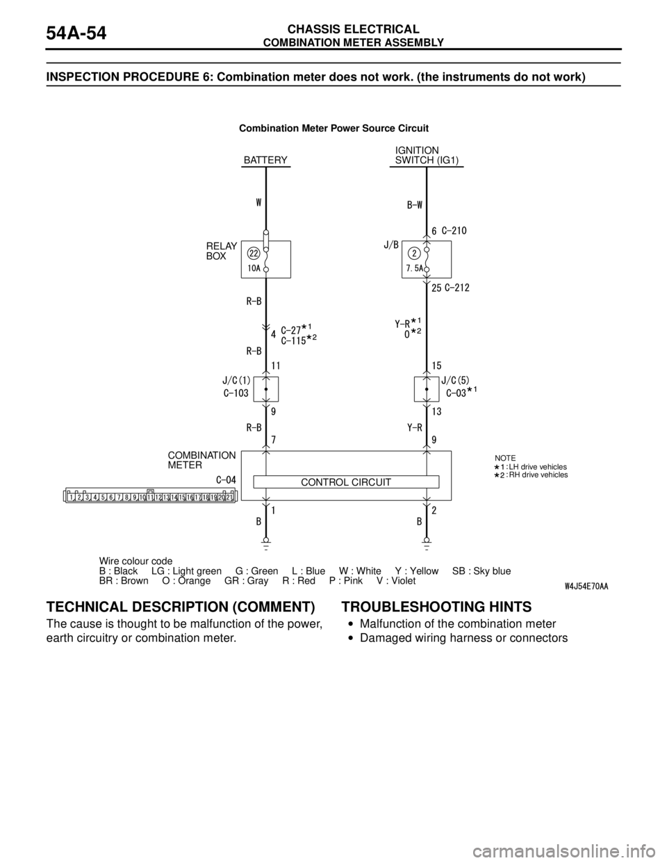
INSPECTION PROCEDURE 6: Combination meter does not work. (the instruments do not work)
TECHNICAL DESCRIPTION (COMMENT)
The cause is thought to be malfunction of the power,
earth circuitry or combination meter.
TROUBLESHOOTING HINTS
•Malfunction of the combination meter
•Damaged wiring harness or connectors
Wire colour code
B : Black LG : Light green G : Green L : Blue W : White Y : Yellow SB : Sky blue
BR : Brown O : Orange GR : Gray R : Red P : Pink V : Violet IGNITION
SWITCH (IG1)
COMBINATION
METER
CONTROL CIRCUIT BATTERY
RELAY
BOX
NOTELH drive vehicles
RH drive vehicles
Combination Meter Power Source Circuit
Page 454 of 788
HEADLAMP
CHASSIS ELECTRICAL54A-66
HEADLAMP
SERVICE SPECIFICATIONSM1542000300332
TROUBLESHOOTING M1542000701281
Features the headlamp automatic shutdown function
to avoid battery drain when the headlamps are left
on. The main features are as follows:
•Extinguishes automatically in three minutes if the
ignition switch is turned off with the lighting switch
on.
•Extinguishes in one second if the driver's door is
opened within that 3-minute period.
•If the headlamps are turned on with the ignition
switch off, the headlamps and tail lamps will
extinguish in three minutes after the driver's door
is opened or closed.
The headlamps are controlled by the Smart Wiring
System (SWS). For troubleshooting, refer to
respective Groups below.
•Not using SWS monitor: GROUP 54B, SWS
Troubleshooting P.54B-38.
•Using SWS monitor: GROUP 54C, SWS
Troubleshooting P.54C-22.
ON-VEHICLE SERVICE
HEADLAMP AIMING
M1542000900538
PRE-AIMING INSTRUCTIONS
1. Inspect for badly rusted or faulty headlamp
assemblies.
2. These conditions must be corrected before a
satisfactory adjustment can be made.
3. Inspect tyre inflation, and adjust if it is necessary.
4. If the fuel tank is not full, place a weight in luggage
room of the vehicle to simulate weight of a full
tank (0.8 kg per litre).
5. There should be no other load in the vehicle other
than driver or substituted weight of approximately
75 kg placed in driver's position.
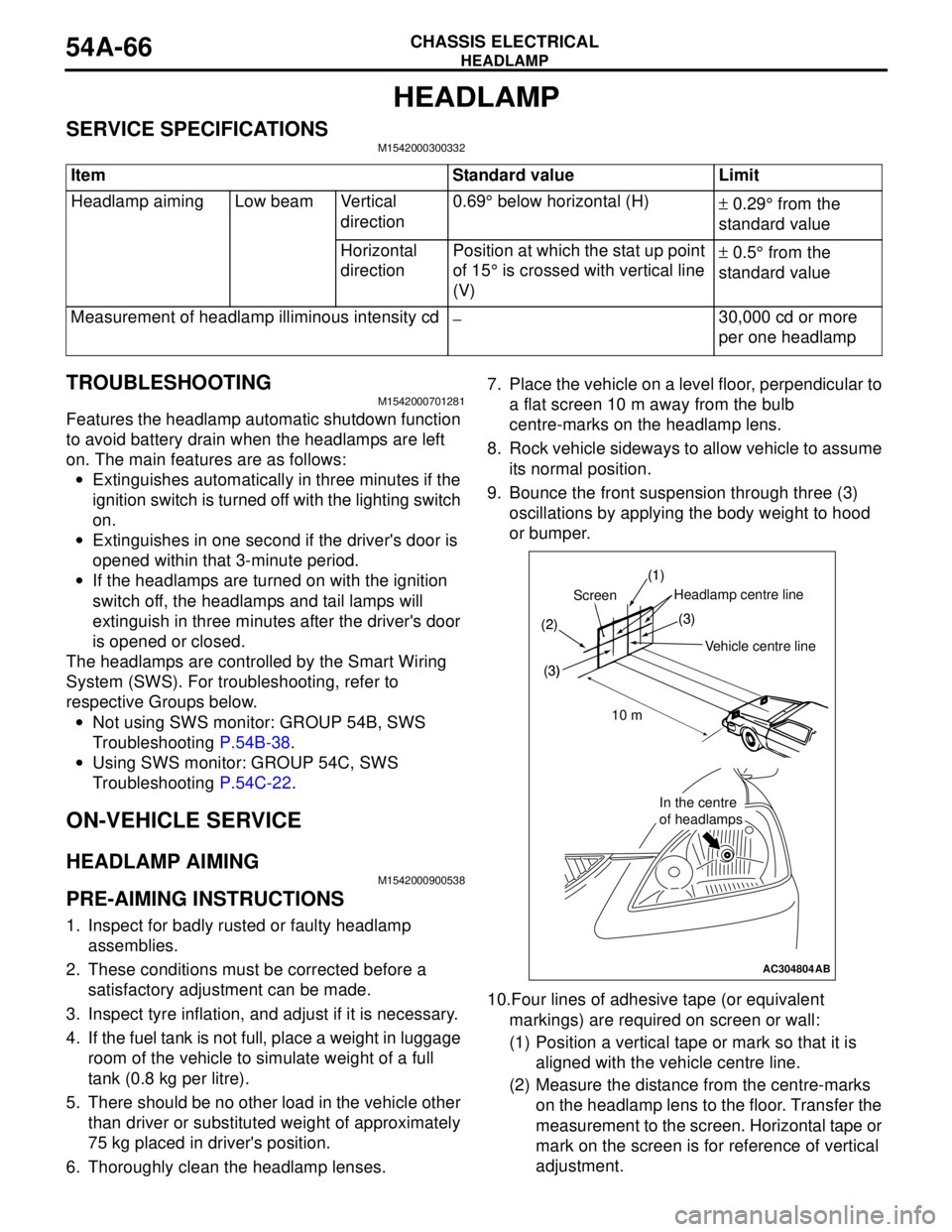
6. Thoroughly clean the headlamp lenses.7. Place the vehicle on a level floor, perpendicular to
a flat screen 10 m away from the bulb
centre-marks on the headlamp lens.
8. Rock vehicle sideways to allow vehicle to assume
its normal position.
9. Bounce the front suspension through three (3)
oscillations by applying the body weight to hood
or bumper.
10.Four lines of adhesive tape (or equivalent
markings) are required on screen or wall:
(1) Position a vertical tape or mark so that it is
aligned with the vehicle centre line.
(2) Measure the distance from the centre-marks
on the headlamp lens to the floor. Transfer the
measurement to the screen. Horizontal tape or
mark on the screen is for reference of vertical
adjustment. Item Standard value Limit
Headlamp aiming Low beam Vertical
direction0.69° below horizontal (H)
± 0.29° from the
standard value
Horizontal
directionPosition at which the stat up point
of 15° is crossed with vertical line
(V)± 0.5° from the
standard value
Measurement of headlamp illiminous intensity cd
−30,000 cd or more
per one headlamp
AC304804
(1)
(2)
(3)
Headlamp centre line
Vehicle crntre line Screen
(3)
10 m
In the centre
of headlamps
(1)
(2)
(3)(3)
In the centre
of headlamps
AB
Vehicle centre line
ScreenHeadlamp centre line
10 m