15-3 MITSUBISHI LANCER 2005 Workshop Manual
[x] Cancel search | Manufacturer: MITSUBISHI, Model Year: 2005, Model line: LANCER, Model: MITSUBISHI LANCER 2005Pages: 788, PDF Size: 45.98 MB
Page 40 of 788

THERMOSTAT
ENGINE COOLING14-26
THERMOSTAT
REMOVAL AND INSTALLATIONM1141002400442
Pre-removal and Post-installation Operation
•Engine Coolant Draining and Refilling (Refer to P.14-22).
•Air Cleaner Assembly Removal and Installation (Refer to
GROUP 15 P.15-3).
•Battery Removal and Installation
AC203409AC
4
3 6 7
22 ± 4 N·m
<4G1>
AC301429
1
2
36 7
13 ± 2 N·m
AD
5
<4G6>
Page 45 of 788
WATER HOSE AND WATER PIPE
ENGINE COOLING14-31
WATER HOSE AND WATER PIPE
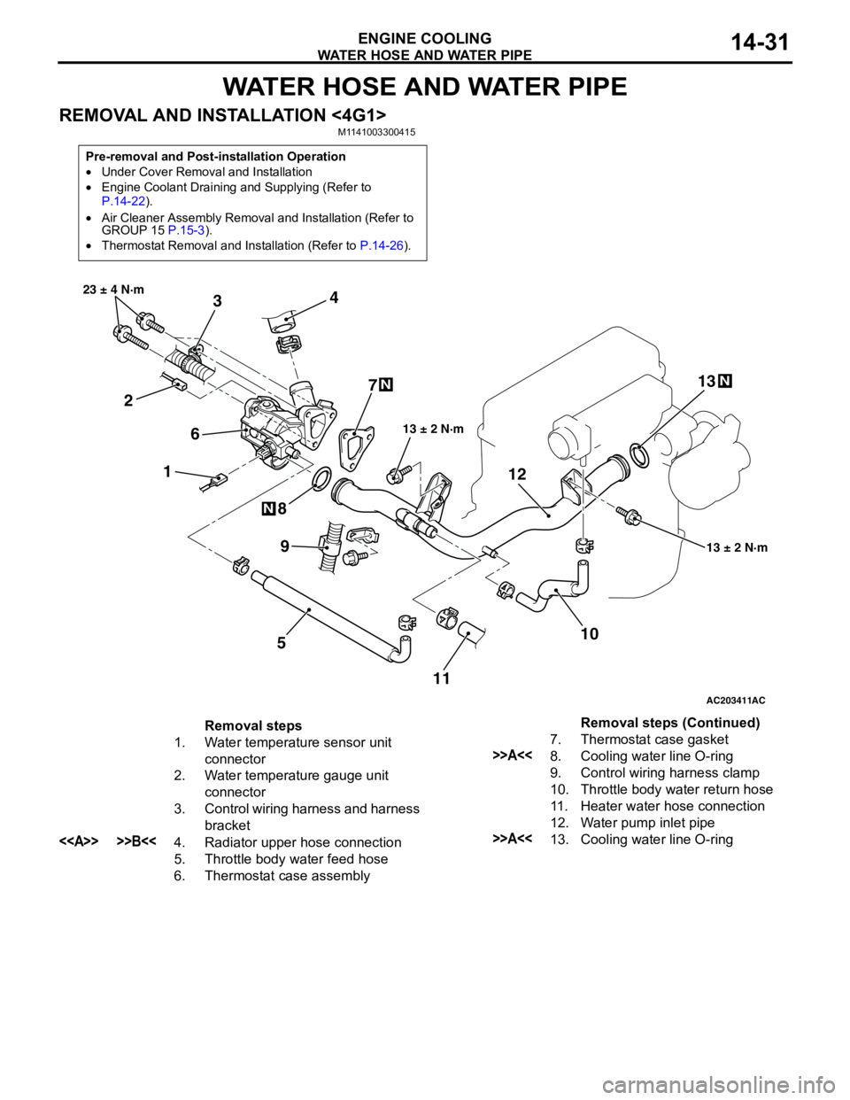
REMOVAL AND INSTALLATION <4G1>M1141003300415
Pre-removal and Post-installation Operation
•Under Cover Removal and Installation
•Engine Coolant Draining and Supplying (Refer to
P.14-22).
•Air Cleaner Assembly Removal and Installation (Refer to
GROUP 15 P.15-3).
•Thermostat Removal and Installation (Refer to P.14-26).
AC203411
1 234
5 67
8
10 9
13 ± 2 N·m 23 ± 4 N·m
13 ± 2 N·m
N
N
AC
111213
N
Removal steps
1. Water temperature sensor unit
connector
2. Water temperature gauge unit
connector
3. Control wiring harness and harness
bracket
<> >>B<<4. Radiator upper hose connection
5. Throttle body water feed hose
6. Thermostat case assembly7. Thermostat case gasket
>>A<<8. Cooling water line O-ring
9. Control wiring harness clamp
10. Throttle body water return hose
11. Heater water hose connection
12. Water pump inlet pipe
>>A<<13. Cooling water line O-ringRemoval steps (Continued)
Page 47 of 788
WATER HOSE AND WATER PIPE
ENGINE COOLING14-33
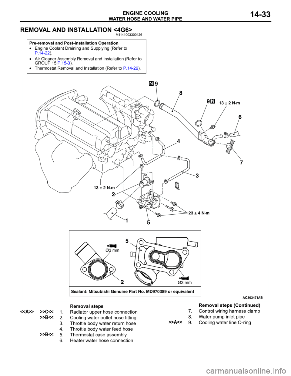
REMOVAL AND INSTALLATION <4G6>M1141003300426
Pre-removal and Post-installation Operation
•Engine Coolant Draining and Supplying (Refer to
P.14-22).
•Air Cleaner Assembly Removal and Installation (Refer to
GROUP 15 P.15-3).
•Thermostat Removal and Installation (Refer to P.14-26).
AC303471
1 23 4
56
7 8 9
9
13 ± 2 N·m
23 ± 4 N·m 13 ± 2 N·m
N
N
AB
2
Sealant: Mitsubishi Genuine Part No. MD970389 or equivalentØ3 mm
Ø3 mm
5
Removal steps
<> >>C<<1. Radiator upper hose connection
>>B<<2. Cooling water outlet hose fitting
3. Throttle body water return hose
4. Throttle body water feed hose
>>B<<5. Thermostat case assembly
6. Heater water hose connection7. Control wiring harness clamp
8. Water pump inlet pipe
>>A<<9. Cooling water line O-ringRemoval steps (Continued)
Page 49 of 788
RADIATOR
ENGINE COOLING14-35
RADIATOR
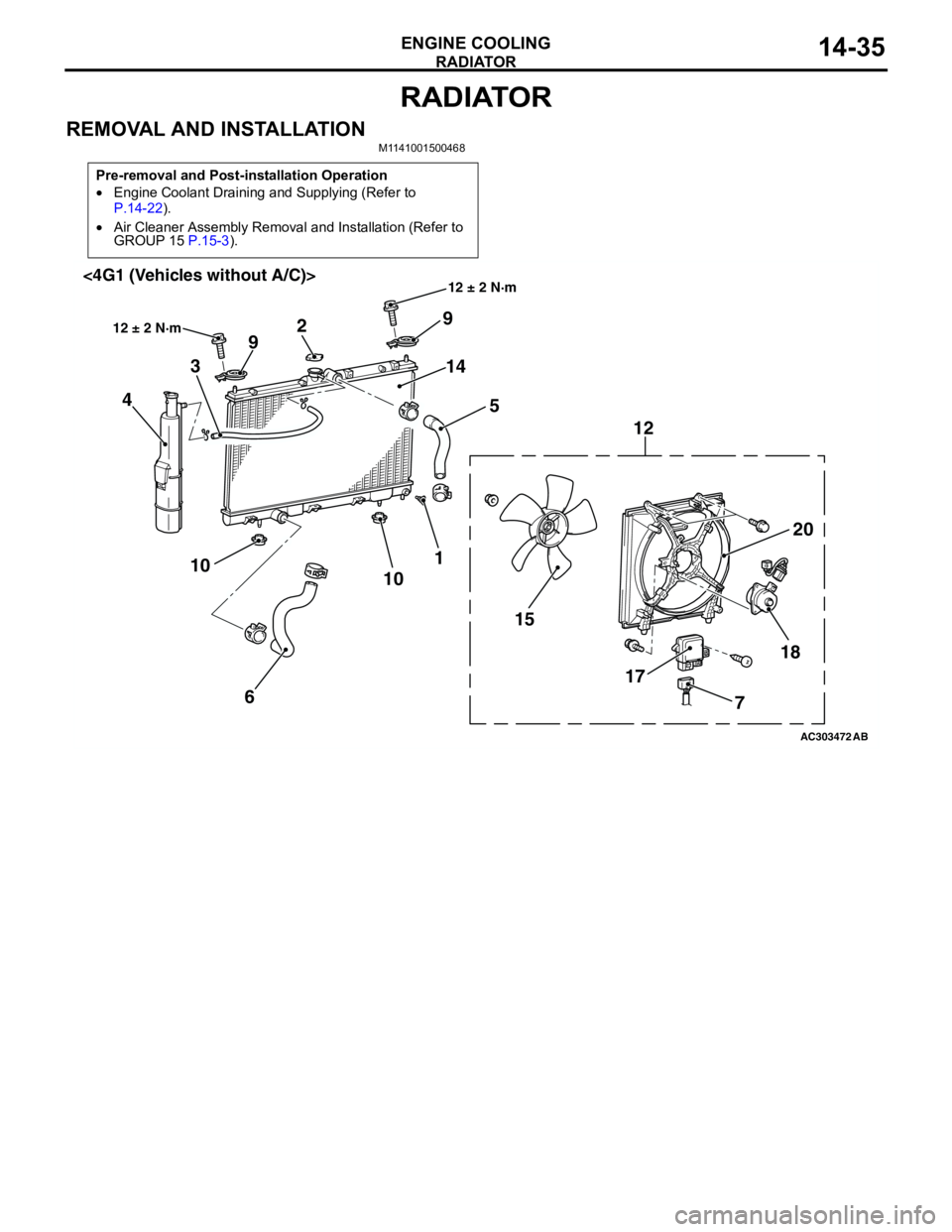
REMOVAL AND INSTALLATIONM1141001500468
Pre-removal and Post-installation Operation
•Engine Coolant Draining and Supplying (Refer to
P.14-22).
•Air Cleaner Assembly Removal and Installation (Refer to
GROUP 15 P.15-3).
AC303472
18
17 1520 12 9
14
5 2
9
3
4
1
10
6 10
AB
12 ± 2 N·m
12 ± 2 N·m<4G1 (Vehicles without A/C)>
7
Page 53 of 788
15-1
GROUP 15
INTAKE AND
EXHAUST
CONTENTS
GENERAL INFORMATION . . . . . . . .15-2
SERVICE SPECIFICATION . . . . . . . .15-2
SPECIAL TOOL . . . . . . . . . . . . . . . . .15-2
AIR CLEANER . . . . . . . . . . . . . . . . . .15-3
REMOVAL AND INSTALLATION . . . . . . . . 15-3
INLET MANIFOLD . . . . . . . . . . . . . . .15-5
REMOVAL AND INSTALLATION <4G1> . . 15-5REMOVAL AND INSTALLATION <4G6> . . 15-6
INSPECTION . . . . . . . . . . . . . . . . . . . . . . . . 15-7
EXHAUST MANIFOLD . . . . . . . . . . . .15-7
REMOVAL AND INSTALLATION <4G1> . . 15-7
REMOVAL AND INSTALLATION <4G6> . . 15-9
INSPECTION . . . . . . . . . . . . . . . . . . . . . . . . 15-10
EXHAUST PIPE AND MAIN
MUFFLER . . . . . . . . . . . . . . . . . . . . . .15-11
REMOVAL AND INSTALLATION . . . . . . . . 15-11
Page 55 of 788
AIR CLEANER
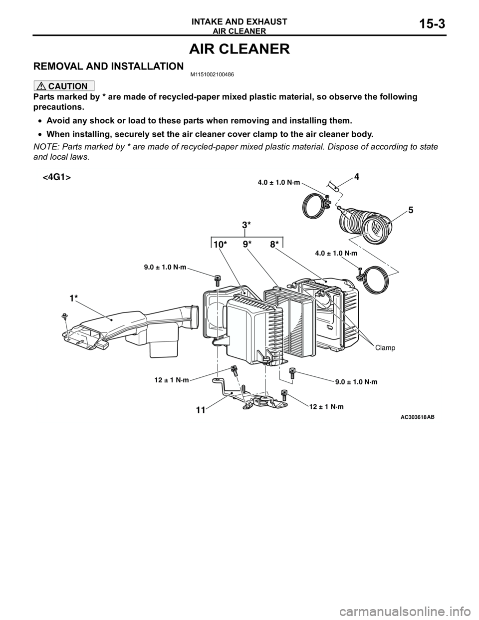
INTAKE AND EXHAUST15-3
AIR CLEANER
REMOVAL AND INSTALLATIONM1151002100486
CAUTION
Parts marked by * are made of recycled-paper mixed plastic material, so observe the following
precautions.
•Avoid any shock or load to these parts when removing and installing them.
•When installing, securely set the air cleaner cover clamp to the air cleaner body.
NOTE: Parts marked by * are made of recycled-paper mixed plastic material. Dispose of according to state
and local laws.
AC303618
4.0 ± 1.0 N·m 4.0 ± 1.0 N·m
10*9*4
1*5
11
12 ± 1 N·m
9.0 ± 1.0 N·m 9.0 ± 1.0 N·m
AB
12 ± 1 N·m
Clamp
8*
3* <4G1>
Page 77 of 788
CHARGING SYSTEM
ENGINE ELECTRICAL16-13
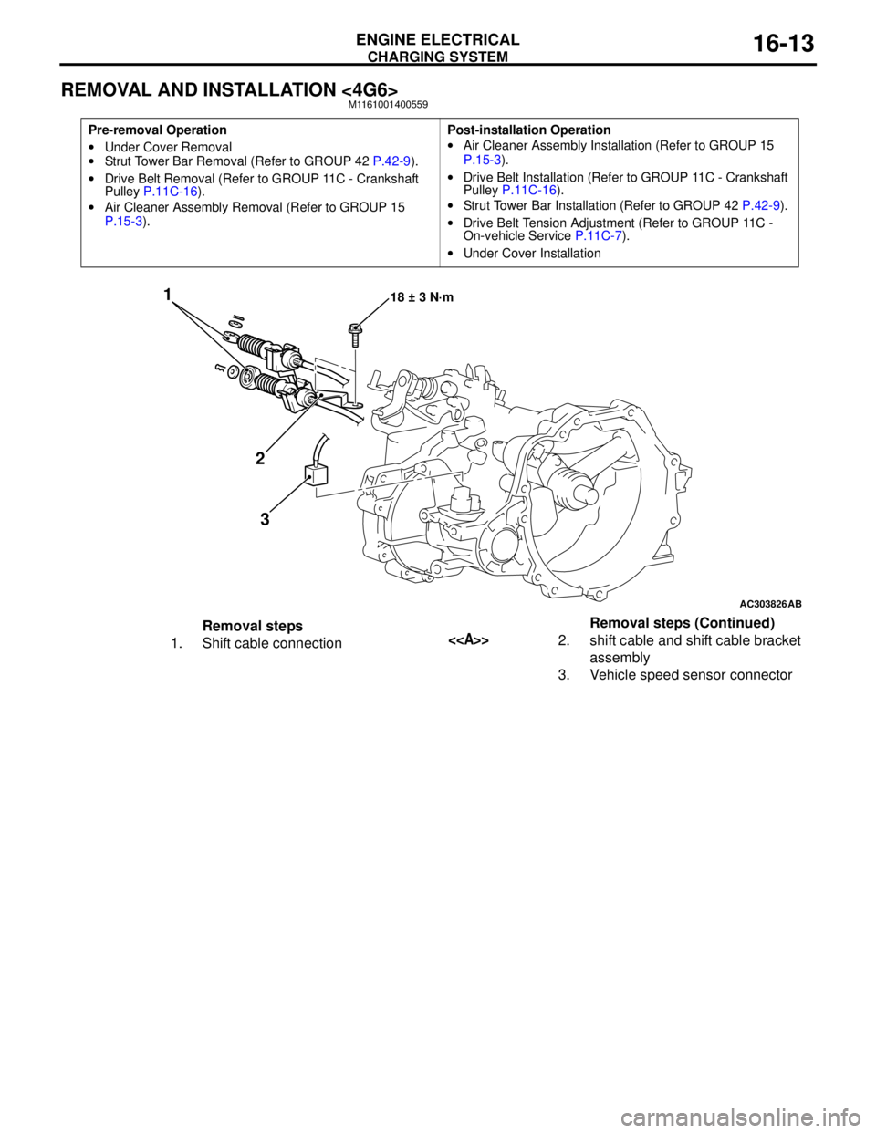
REMOVAL AND INSTALLATION <4G6>M1161001400559
Pre-removal Operation
•Under Cover Removal
•Strut Tower Bar Removal (Refer to GROUP 42 P.42-9).
•Drive Belt Removal (Refer to GROUP 11C - Crankshaft
Pulley P.11C-16).
•Air Cleaner Assembly Removal (Refer to GROUP 15
P.15-3).Post-installation Operation
•Air Cleaner Assembly Installation (Refer to GROUP 15
P.15-3).
•Drive Belt Installation (Refer to GROUP 11C - Crankshaft
Pulley P.11C-16).
•Strut Tower Bar Installation (Refer to GROUP 42 P.42-9).
•Drive Belt Tension Adjustment (Refer to GROUP 11C -
On-vehicle Service P.11C-7).
•Under Cover Installation
AC303826
1
2
318 ± 3 N·m
AB
Removal steps
1. Shift cable connection<>2. shift cable and shift cable bracket
assembly
3. Vehicle speed sensor connectorRemoval steps (Continued)
Page 85 of 788

STARTING SYSTEM
ENGINE ELECTRICAL16-21
STARTER MOTOR ASSEMBLY
REMOVAL AND INSTALLATION <4G1>M1162001000628
REMOVAL SERVICE POINT
<> SHIFT CABLE AND SHIFT CABLE
BRACKET ASSEMBLY
Remove the shift cable bracket installation bolt with
the shift cable installed on the shift cable bracket,
and remove the shift cable and shift cable bracket
assembly from the transmission.
<> SHIFT CABLE CONNECTION
REMOVAL
Disengage the transmission, and remove the shift
cable assembly from the transmission.
<
Remove the starter assembly from above the
vehicle.
Pre-removal and Post-installation Operation
•Air Cleaner Assembly Removal and Installation (Refer to
GROUP 15 P.15-3).
•Battery and Battery Tray Removal and Installation
AC303962AB
1
1 2
3
56
7
4
30 ± 3 N·m18 ± 3 N·m
12 ± 2 N·m
Removal steps
1. Shift cable connection
<>2. shift cable and shift cable bracket
assembly
<>3. Shift cable connection 4. Starter connector and terminal
5. Harness bracket
6. Harness bracket <
Page 86 of 788
STARTING SYSTEM
ENGINE ELECTRICAL16-22
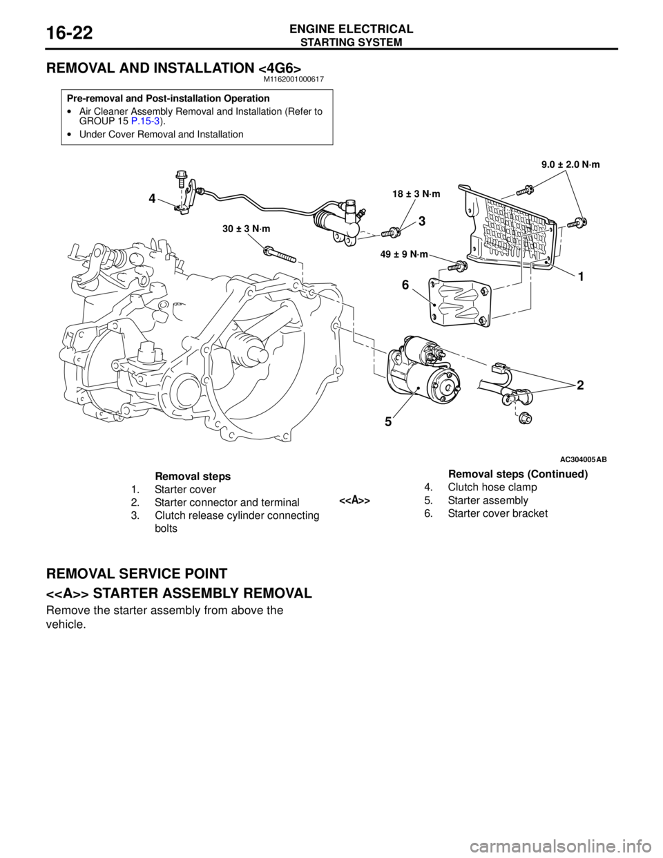
REMOVAL AND INSTALLATION <4G6>M1162001000617
REMOVAL SERVICE POINT
<> STARTER ASSEMBLY REMOVAL
Remove the starter assembly from above the
vehicle.
Pre-removal and Post-installation Operation
•Air Cleaner Assembly Removal and Installation (Refer to
GROUP 15 P.15-3).
•Under Cover Removal and Installation
AC304005
521
6
49 ± 9 N·m 18 ± 3 N·m9.0 ± 2.0 N·m
30 ± 3 N·m
AB
4
3
Removal steps
1. Starter cover
2. Starter connector and terminal
3. Clutch release cylinder connecting
bolts4. Clutch hose clamp
<>5. Starter assembly
6. Starter cover bracketRemoval steps (Continued)
Page 120 of 788
EMISSION CONTROL
ENGINE AND EMISSION CONTROL17-12
4. Check airtightness by applying a vacuum with
voltage applied directly from the battery to the
purge control solenoid valve and without applying
voltage.
5. Measure the resistance between the terminals of
the solenoid valve.
Standard value: 30 − 34 Ω (at 20°C)
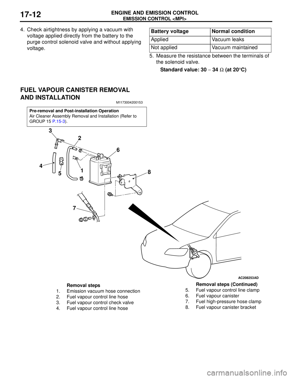
FUEL VAPOUR CANISTER REMOVAL
AND INSTALLATION
M1173004200153
Battery voltage Normal condition
Applied Vacuum leaks
Not applied Vacuum maintained
Pre-removal and Post-installation Operation
Air Cleaner Assembly Removal and Installation (Refer to
GROUP 15 P.15-3).
AC208253
1 2 3
4
56
78
AD
Removal steps
1. Emission vacuum hose connection
2. Fuel vapour control line hose
3. Fuel vapour control check valve
4. Fuel vapour control line hose5. Fuel vapour control line clamp
6. Fuel vapour canister
7. Fuel high-pressure hose clamp
8. Fuel vapour canister bracketRemoval steps (Continued)