heater MITSUBISHI LANCER 2005 Workshop Manual
[x] Cancel search | Manufacturer: MITSUBISHI, Model Year: 2005, Model line: LANCER, Model: MITSUBISHI LANCER 2005Pages: 788, PDF Size: 45.98 MB
Page 1 of 788
GROUP INDEX
00General . . . . . . . . . . . . . . . . . . . . . . . .
11Engine. . . . . . . . . . . . . . . . . . . . . . . . .
12Engine Lubrication . . . . . . . . . . . . . .
13Fuel . . . . . . . . . . . . . . . . . . . . . . . . . . .
14Engine Cooling . . . . . . . . . . . . . . . . .
15Intake and Exhaust . . . . . . . . . . . . . .
16Engine Electrical . . . . . . . . . . . . . . . .
17Engine and Emission Control . . . . .
21Clutch . . . . . . . . . . . . . . . . . . . . . . . . .
22Manual Transmission . . . . . . . . . . . .
23Automatic Transmission. . . . . . . . . .
26Front Axle . . . . . . . . . . . . . . . . . . . . . .
27Rear Axle . . . . . . . . . . . . . . . . . . . . . .
31Wheel and Tyre . . . . . . . . . . . . . . . . .
32Power Plant Mount . . . . . . . . . . . . . .
33Front Suspension . . . . . . . . . . . . . . .
34Rear Suspension . . . . . . . . . . . . . . . .
35Service Brakes . . . . . . . . . . . . . . . . . .
36Parking Brakes . . . . . . . . . . . . . . . . .
37Power Steering . . . . . . . . . . . . . . . . .
42Body . . . . . . . . . . . . . . . . . . . . . . . . . .
51Exterior . . . . . . . . . . . . . . . . . . . . . . . .
52 . . . . . . . . . .
54Chassis Electrical . . . . . . . . . . . . . . .
55 . . . . . . .
70Component Locations. . . . . . . . . . . .
80Configration Diagrams . . . . . . . . . . .
90Circuit Diagrams . . . . . . . . . . . . . . . .
LANCER /
LANCER WAGON
WORKSHOP MANUAL
FOREWORD
This Workshop manual contains procedures for
service mechanics, including removal, disassembly,
inspection, adjustment, reassembly and installation.
Use the following manuals in combination with this
manual as required.
TECHNICAL INFORMATION MANUAL
PYME0302
PYME0302-A
WORKSHOP MANUAL
CHASSIS GROUP PWME0302
BODY REPAIR MANUAL
PBME0302
PBME0302-A
PARTS CATALOGUE
B606K005A_
All information, illustrations and product descriptions
contained in this manual are current as at the time of
publication. We, however, reserve the right to make
changes at any time without prior notice or obligation.
Mitsubishi Motors Corporation May 2004
Heater, Air Conditioner and
Ventilation Interior and Supplemental
Restraint System (SRS)
Page 36 of 788
ON-VEHICLE SERVICE
ENGINE COOLING14-22
ON-VEHICLE SERVICE
ENGINE COOLANT LEAK CHECKM1141001000300
WARNING
When pressure testing the cooling system,
slowly release cooling system pressure to
avoid getting burned by hot coolant.
CAUTION
•Be sure to completely clean away any
moisture from the places checked.
•When the tester is taken out, be careful not to
spill any coolant.
•Be careful when installing and removing the
tester and when testing not to deform the
filler neck of the radiator.
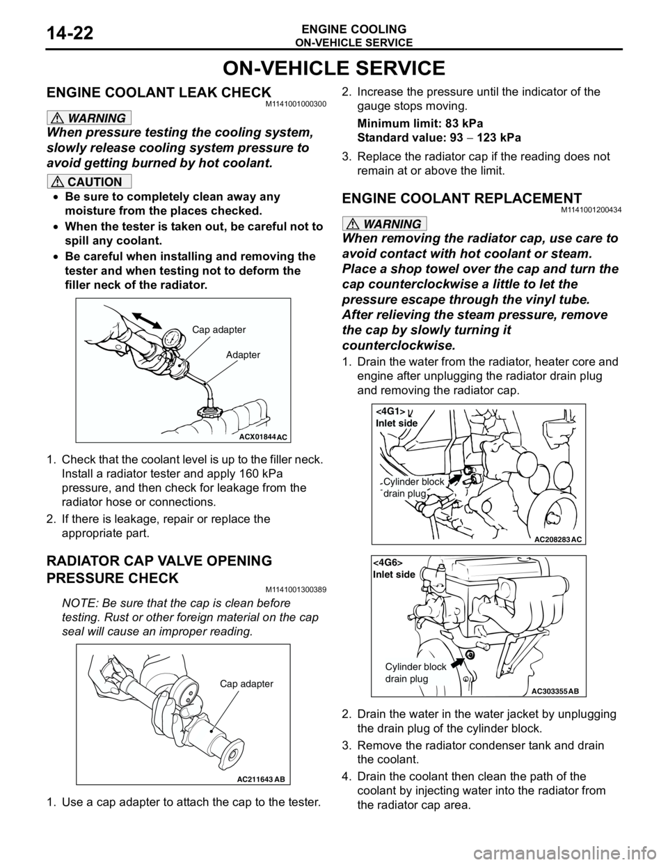
1. Check that the coolant level is up to the filler neck.
Install a radiator tester and apply 160 kPa
pressure, and then check for leakage from the
radiator hose or connections.
2. If there is leakage, repair or replace the
appropriate part.
RADIATOR CAP VALVE OPENING
PRESSURE CHECK
M1141001300389
NOTE: Be sure that the cap is clean before
testing. Rust or other foreign material on the cap
seal will cause an improper reading.
1. Use a cap adapter to attach the cap to the tester.2. Increase the pressure until the indicator of the
gauge stops moving.
Minimum limit: 83 kPa
Standard value: 93 − 123 kPa
3. Replace the radiator cap if the reading does not
remain at or above the limit.
ENGINE COOLANT REPLACEMENTM1141001200434
WARNING
When removing the radiator cap, use care to
avoid contact with hot coolant or steam.
Place a shop towel over the cap and turn the
cap counterclockwise a little to let the
pressure escape through the vinyl tube.
After relieving the steam pressure, remove
the cap by slowly turning it
counterclockwise.
1. Drain the water from the radiator, heater core and
engine after unplugging the radiator drain plug
and removing the radiator cap.
2. Drain the water in the water jacket by unplugging
the drain plug of the cylinder block.
3. Remove the radiator condenser tank and drain
the coolant.
4. Drain the coolant then clean the path of the
coolant by injecting water into the radiator from
the radiator cap area.
ACX01844
Cap adapter
Adapter
AC
AC211643AB
Cap adapter
AC208283AC
Cylinder block
drain plug
<4G1>
Inlet side
AC303355
<4G6>
Inlet side
Cylinder block
drain plug
AB
Page 45 of 788
WATER HOSE AND WATER PIPE
ENGINE COOLING14-31
WATER HOSE AND WATER PIPE
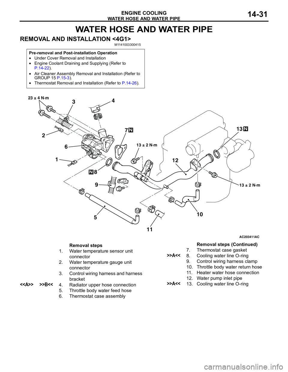
REMOVAL AND INSTALLATION <4G1>M1141003300415
Pre-removal and Post-installation Operation
•Under Cover Removal and Installation
•Engine Coolant Draining and Supplying (Refer to
P.14-22).
•Air Cleaner Assembly Removal and Installation (Refer to
GROUP 15 P.15-3).
•Thermostat Removal and Installation (Refer to P.14-26).
AC203411
1 234
5 67
8
10 9
13 ± 2 N·m 23 ± 4 N·m
13 ± 2 N·m
N
N
AC
111213
N
Removal steps
1. Water temperature sensor unit
connector
2. Water temperature gauge unit
connector
3. Control wiring harness and harness
bracket
<> >>B<<4. Radiator upper hose connection
5. Throttle body water feed hose
6. Thermostat case assembly7. Thermostat case gasket
>>A<<8. Cooling water line O-ring
9. Control wiring harness clamp
10. Throttle body water return hose
11. Heater water hose connection
12. Water pump inlet pipe
>>A<<13. Cooling water line O-ringRemoval steps (Continued)
Page 47 of 788
WATER HOSE AND WATER PIPE
ENGINE COOLING14-33
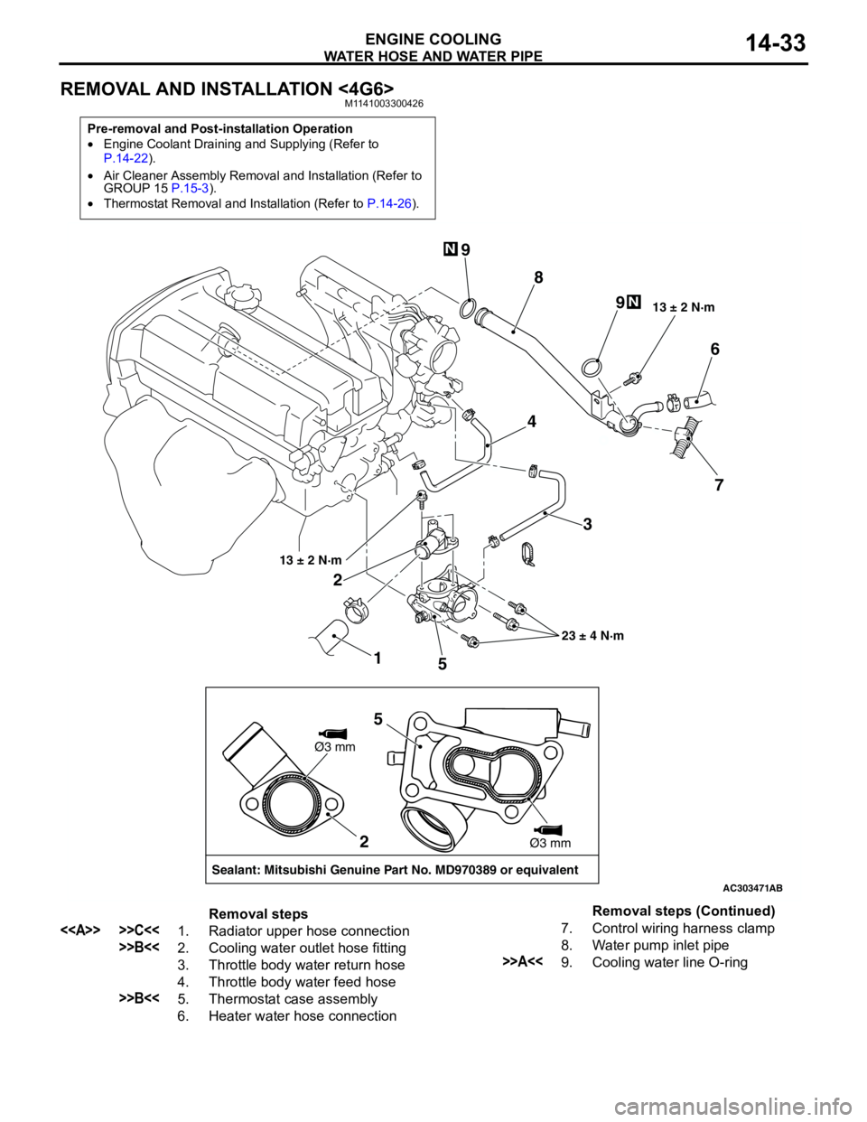
REMOVAL AND INSTALLATION <4G6>M1141003300426
Pre-removal and Post-installation Operation
•Engine Coolant Draining and Supplying (Refer to
P.14-22).
•Air Cleaner Assembly Removal and Installation (Refer to
GROUP 15 P.15-3).
•Thermostat Removal and Installation (Refer to P.14-26).
AC303471
1 23 4
56
7 8 9
9
13 ± 2 N·m
23 ± 4 N·m 13 ± 2 N·m
N
N
AB
2
Sealant: Mitsubishi Genuine Part No. MD970389 or equivalentØ3 mm
Ø3 mm
5
Removal steps
<> >>C<<1. Radiator upper hose connection
>>B<<2. Cooling water outlet hose fitting
3. Throttle body water return hose
4. Throttle body water feed hose
>>B<<5. Thermostat case assembly
6. Heater water hose connection7. Control wiring harness clamp
8. Water pump inlet pipe
>>A<<9. Cooling water line O-ringRemoval steps (Continued)
Page 70 of 788

CHARGING SYSTEM
ENGINE ELECTRICAL16-6
7. Connect a tachometer or the MUT-II/III (Refer to
GROUP 11A − On-vehicle Service − Idle speed
check <4G1> P.11A-11 or GROUP 11C −
On-vehicle Service − Idle speed check <4G6>
P.11C-11).
8. Leave the hood open.
9. Check that the reading on the voltmeter is equal
to the battery voltage.
NOTE: If the voltage is 0 V, the cause is probably
an open circuit in the wire or fusible link between
the alternator "B" terminal and the battery (+)
terminal.
10.Turn the light switch on to turn on headlamps and
then start the engine.
11.Immediately after setting the headlamps to high
beam and turning the heater blower switch to the
high revolution position, increase the engine
speed to 2,500 r/min and read the maximum
current output value displayed on the ammeter.
Limit: 70 % of normal current outputNOTE: .
•For the nominal current output, refer to the
Alternator Specifications.
•Because the current from the battery will soon
drop after the engine is started, the above step
should be carried out as quickly as possible in
order to obtain the maximum current output
value.
•The current output value will depend on the
electrical load and the temperature of the
alternator body.
•If the electrical load is small while testing, the
specified level of current may not be output
even though the alternator is normal. In such
cases, increase the electrical load by leaving
the headlamps turned on for some time to
discharge the battery or by using the lighting
system in another vehicle, and then test again.
•The specified level of current also may not be
output if the temperature of the alternator body
or the ambient temperature is too high. In such
cases, cool the alternator and then test again.
12.The reading on the ammeter should be above the
limit value. If the reading is below the limit value
and the alternator output wire is normal, remove
the alternator from the engine and check the
alternator.
13.Run the engine at idle after the test.
14.Turn the ignition switch to the "LOCK" (OFF)
position.
15.Remove the tachometer or the MUT-II/III.
16.Disconnect the negative battery cable.
17.Disconnect the ammeter and voltmeter.
18.Connect the negative battery cable.
Page 374 of 788
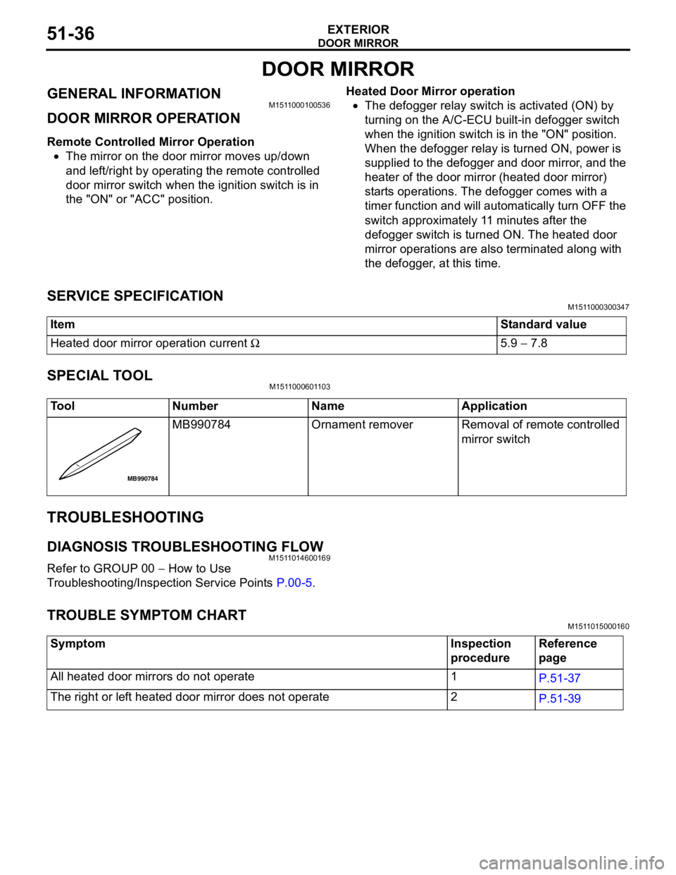
DOOR MIRROR
EXTERIOR51-36
DOOR MIRROR
GENERAL INFORMATIONM1511000100536
DOOR MIRROR OPERATION
Remote Controlled Mirror Operation
•The mirror on the door mirror moves up/down
and left/right by operating the remote controlled
door mirror switch when the ignition switch is in
the "ON" or "ACC" position.Heated Door Mirror operation
•The defogger relay switch is activated (ON) by
turning on the A/C-ECU built-in defogger switch
when the ignition switch is in the "ON" position.
When the defogger relay is turned ON, power is
supplied to the defogger and door mirror, and the
heater of the door mirror (heated door mirror)
starts operations. The defogger comes with a
timer function and will automatically turn OFF the
switch approximately 11 minutes after the
defogger switch is turned ON. The heated door
mirror operations are also terminated along with
the defogger, at this time.
SERVICE SPECIFICATIONM1511000300347
SPECIAL TOOLM1511000601103
TROUBLESHOOTING
DIAGNOSIS TROUBLESHOOTING FLOWM1511014600169
Refer to GROUP 00 − How to Use
Troubleshooting/Inspection Service Points P.00-5.
TROUBLE SYMPTOM CHARTM1511015000160
ItemStandard value
Heated door mirror operation current Ω5.9 − 7.8
Tool Number Name Application
MB990784 Ornament remover Removal of remote controlled
mirror switch
MB990784
Symptom Inspection
procedureReference
page
All heated door mirrors do not operate 1
P.51-37
The right or left heated door mirror does not operate 2
P.51-39
Page 375 of 788
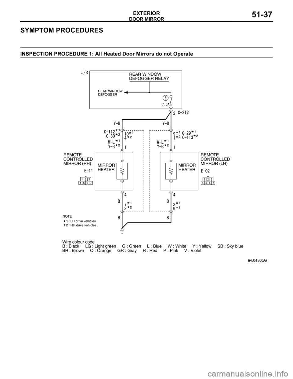
DOOR MIRROR
EXTERIOR51-37
SYMPTOM PROCEDURES
INSPECTION PROCEDURE 1: All Heated Door Mirrors do not Operate
Wire colour code
B : Black LG : Light green G : Green L : Blue W : White Y : Yellow SB : Sky blue
BR : Brown O : Orange GR : Gray R : Red P : Pink V : Violet REAR WINDOW
DEFOGGER RELAY
REAR WINDOW
DEFOGGER
REMOTE
CONTROLLED
MIRROR (LH) REMOTE
CONTROLLED
MIRROR (RH)
MIRROR
HEATERMIRROR
HEATER
NOTELH drive vehicles
RH drive vehicles
Page 376 of 788
DOOR MIRROR
EXTERIOR51-38
COMMENTS ON TROUBLE SYMPTOM
The heated door mirrors should works for
approximately 11 minutes when the rear defogger
switch is turned on. If the mirror heater does not work
for the specified period, the defogger relay circuit
(heated door mirror power supply circuit) may be
defective.
Possible causes
•Damaged harness wires and connectors
DIAGNOSIS PROCEDURE
STEP 1. Check the rear window defogger.
Check that the rear window defogger system should
work normally.
Q: Is the check result normal?
YES :
Go to Step 2.
NO : Troubleshoot the rear window defogger
(Refer to GROUP 55,
TroubleshootingP.55-42).
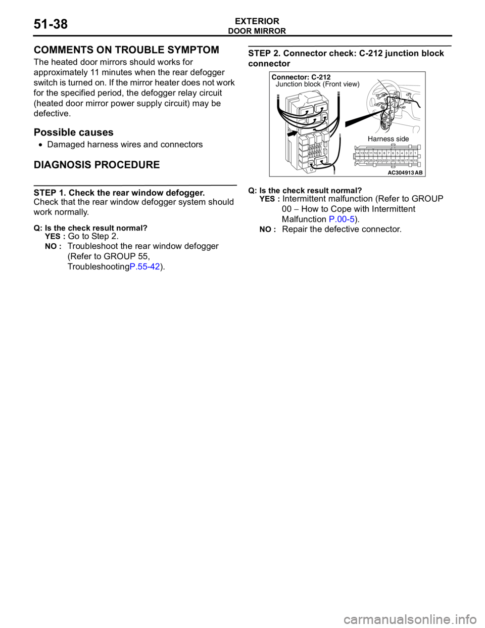
STEP 2. Connector check: C-212 junction block
connector
Q: Is the check result normal?
YES :
Intermittent malfunction (Refer to GROUP
00 − How to Cope with Intermittent
Malfunction P.00-5).
NO : Repair the defective connector.
AC304913
21716151718 201912345 623 222425282627981011141213
Connector: C-212
Harness side
AB
Junction block (Front view)
Page 377 of 788
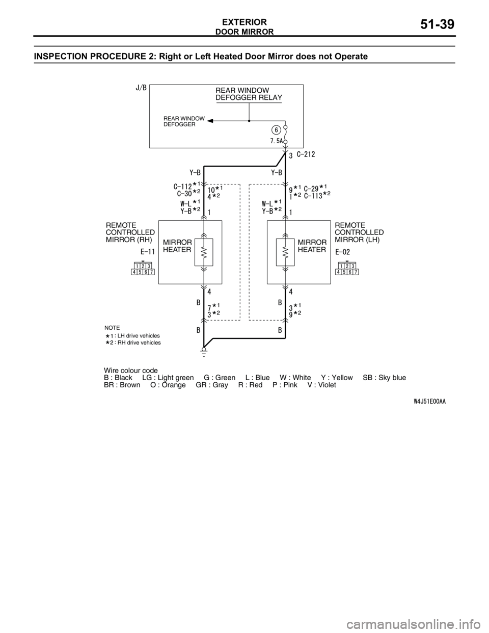
DOOR MIRROR
EXTERIOR51-39
INSPECTION PROCEDURE 2: Right or Left Heated Door Mirror does not Operate
Wire colour code
B : Black LG : Light green G : Green L : Blue W : White Y : Yellow SB : Sky blue
BR : Brown O : Orange GR : Gray R : Red P : Pink V : Violet REAR WINDOW
DEFOGGER RELAY
REAR WINDOW
DEFOGGER
REMOTE
CONTROLLED
MIRROR (LH) REMOTE
CONTROLLED
MIRROR (RH)
MIRROR
HEATERMIRROR
HEATER
NOTELH drive vehicles
RH drive vehicles
Page 378 of 788
DOOR MIRROR
EXTERIOR51-40
COMMENTS ON TROUBLE SYMPTOM
If either of the heated door mirrors does not work, the
door mirror assembly may be defective.
Possible causes
•Malfunction of the door mirror assembly
•Damaged harness wires and connectors
DIAGNOSIS PROCEDURE
Step 1. Verify the operation of each heated door
mirror.
Q: Which door mirror does not heat?
Door mirror (RH) :
Go to Step 2.
Door mirror (LH) : Go to Step 9.
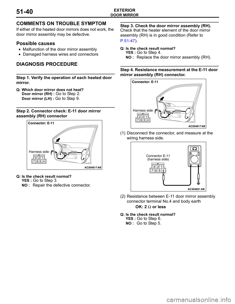
Step 2. Connector check: E-11 door mirror
assembly (RH) connector
Q: Is the check result normal?
YES :
Go to Step 3.
NO : Repair the defective connector.
Step 3. Check the door mirror assembly (RH).
Check that the heater element of the door mirror
assembly (RH) is in good condition (Refer to
P.51-47).
Q: Is the check result normal?
YES :
Go to Step 4.
NO : Replace the door mirror assembly (RH).
Step 4. Resistance measurement at the E-11 door
mirror assembly (RH) connector.
(1) Disconnect the connector, and measure at the
wiring harness side.
(2) Resistance between E-11 door mirror assembly
connector terminal No.4 and body earth
OK: 2 Ω or less
Q: Is the check result normal?
YES :
Go to Step 6.
NO : Go to Step 5.
AC304817
Connector: E-11
Harness side
AB
AC304817
Connector: E-11
Harness side
AB
AC304821
Connector E-11
(harness side)
AB