Automatic MITSUBISHI LANCER 2005 Workshop Manual
[x] Cancel search | Manufacturer: MITSUBISHI, Model Year: 2005, Model line: LANCER, Model: MITSUBISHI LANCER 2005Pages: 788, PDF Size: 45.98 MB
Page 1 of 788
GROUP INDEX
00General . . . . . . . . . . . . . . . . . . . . . . . .
11Engine. . . . . . . . . . . . . . . . . . . . . . . . .
12Engine Lubrication . . . . . . . . . . . . . .
13Fuel . . . . . . . . . . . . . . . . . . . . . . . . . . .
14Engine Cooling . . . . . . . . . . . . . . . . .
15Intake and Exhaust . . . . . . . . . . . . . .
16Engine Electrical . . . . . . . . . . . . . . . .
17Engine and Emission Control . . . . .
21Clutch . . . . . . . . . . . . . . . . . . . . . . . . .
22Manual Transmission . . . . . . . . . . . .
23Automatic Transmission. . . . . . . . . .
26Front Axle . . . . . . . . . . . . . . . . . . . . . .
27Rear Axle . . . . . . . . . . . . . . . . . . . . . .
31Wheel and Tyre . . . . . . . . . . . . . . . . .
32Power Plant Mount . . . . . . . . . . . . . .
33Front Suspension . . . . . . . . . . . . . . .
34Rear Suspension . . . . . . . . . . . . . . . .
35Service Brakes . . . . . . . . . . . . . . . . . .
36Parking Brakes . . . . . . . . . . . . . . . . .
37Power Steering . . . . . . . . . . . . . . . . .
42Body . . . . . . . . . . . . . . . . . . . . . . . . . .
51Exterior . . . . . . . . . . . . . . . . . . . . . . . .
52 . . . . . . . . . .
54Chassis Electrical . . . . . . . . . . . . . . .
55 . . . . . . .
70Component Locations. . . . . . . . . . . .
80Configration Diagrams . . . . . . . . . . .
90Circuit Diagrams . . . . . . . . . . . . . . . .
LANCER /
LANCER WAGON
WORKSHOP MANUAL
FOREWORD
This Workshop manual contains procedures for
service mechanics, including removal, disassembly,
inspection, adjustment, reassembly and installation.
Use the following manuals in combination with this
manual as required.
TECHNICAL INFORMATION MANUAL
PYME0302
PYME0302-A
WORKSHOP MANUAL
CHASSIS GROUP PWME0302
BODY REPAIR MANUAL
PBME0302
PBME0302-A
PARTS CATALOGUE
B606K005A_
All information, illustrations and product descriptions
contained in this manual are current as at the time of
publication. We, however, reserve the right to make
changes at any time without prior notice or obligation.
Mitsubishi Motors Corporation May 2004
Heater, Air Conditioner and
Ventilation Interior and Supplemental
Restraint System (SRS)
Page 94 of 788
IGNITION SYSTEM
ENGINE ELECTRICAL16-30
IGNITION SYSTEM
GENERAL INFORMATIONM1163000100294
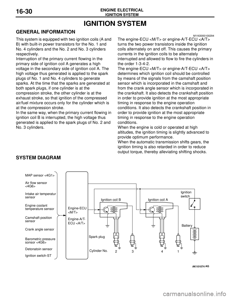
This system is equipped with two ignition coils (A and
B) with built-in power transistors for the No. 1 and
No. 4 cylinders and the No. 2 and No. 3 cylinders
respectively.
Interruption of the primary current flowing in the
primary side of ignition coil A generates a high
voltage in the secondary side of ignition coil A. The
high voltage thus generated is applied to the spark
plugs of No. 1 and No. 4 cylinders to generate
sparks. At the time that the sparks are generated at
both spark plugs, if one cylinder is at the
compression stroke, the other cylinder is at the
exhaust stroke, so that ignition of the compressed
air/fuel mixture occurs only for the cylinder which is
at the compression stroke.
In the same way, when the primary current flowing in
ignition coil B is interrupted, the high voltage thus
generated is applied to the spark plugs of No. 2 and
No. 3 cylinders.The engine-ECU
turns the two power transistors inside the ignition
coils alternately on and off. This causes the primary
currents in the ignition coils to be alternately
interrupted and allowed to flow to fire the cylinders in
the order 1-3-4-2.
The engine-ECU
determines which ignition coil should be controlled
by means of the signals from the camshaft position
sensor which is incorporated in the camshaft and
from the crank angle sensor which is incorporated in
the crankshaft. It also detects the crankshaft position
in order to provide ignition at the most appropriate
timing in response to the engine operation
conditions. It also detects the crankshaft position in
order to provide ignition at the most appropriate
timing in response to the engine operation
conditions.
When the engine is cold or operated at high
altitudes, the ignition timing is slightly advanced to
provide optimum performance.
When the automatic transmission shifts gears, the
ignition timing is also retarded in order to reduce
output torque, thereby alleviating shifting shocks.
SYSTEM DIAGRAM
AK101074
Air flow sensor
<4G6> MAP sensor <4G1>
Intake air temperatur
sensor
Engine coolant
temperature sensor
Camshaft position
sensor
Crank angle sensor
Barometric pressure
sonsor <4G6>
Detonatoin sensor
Ignition switch-STEngine-A/T-
ECU Engine-ECU
Cylinder No.
23 4
AG
1 Spark plugIgnition coil AIgnition
switch
Battery
Page 131 of 788

23-1
GROUP 23
AUTOMATIC
TRANSMISSION
CONTENTS
AUTOMATIC TRANSMISSION (FF) . . . . . . . . . . . . . . . . . . . . . .23A
AUTOMATIC TRANSMISSION OVERHAUL . . . . . . . . . . . . . . .23B
Page 306 of 788
DOOR
BODY42-28
DOOR WINDOW GLASS ADJUSTMENTM1423001000327
Check that the door glass moves while contacting
the door glass channel when it is raised and lowered
fully. If not, adjust the door window according to the
following procedures.
1. Remove the door trim assembly (Refer to GROUP
52A, Door trim P.52A-15).
2. Remove the waterproof film (Refer to P.42-39).
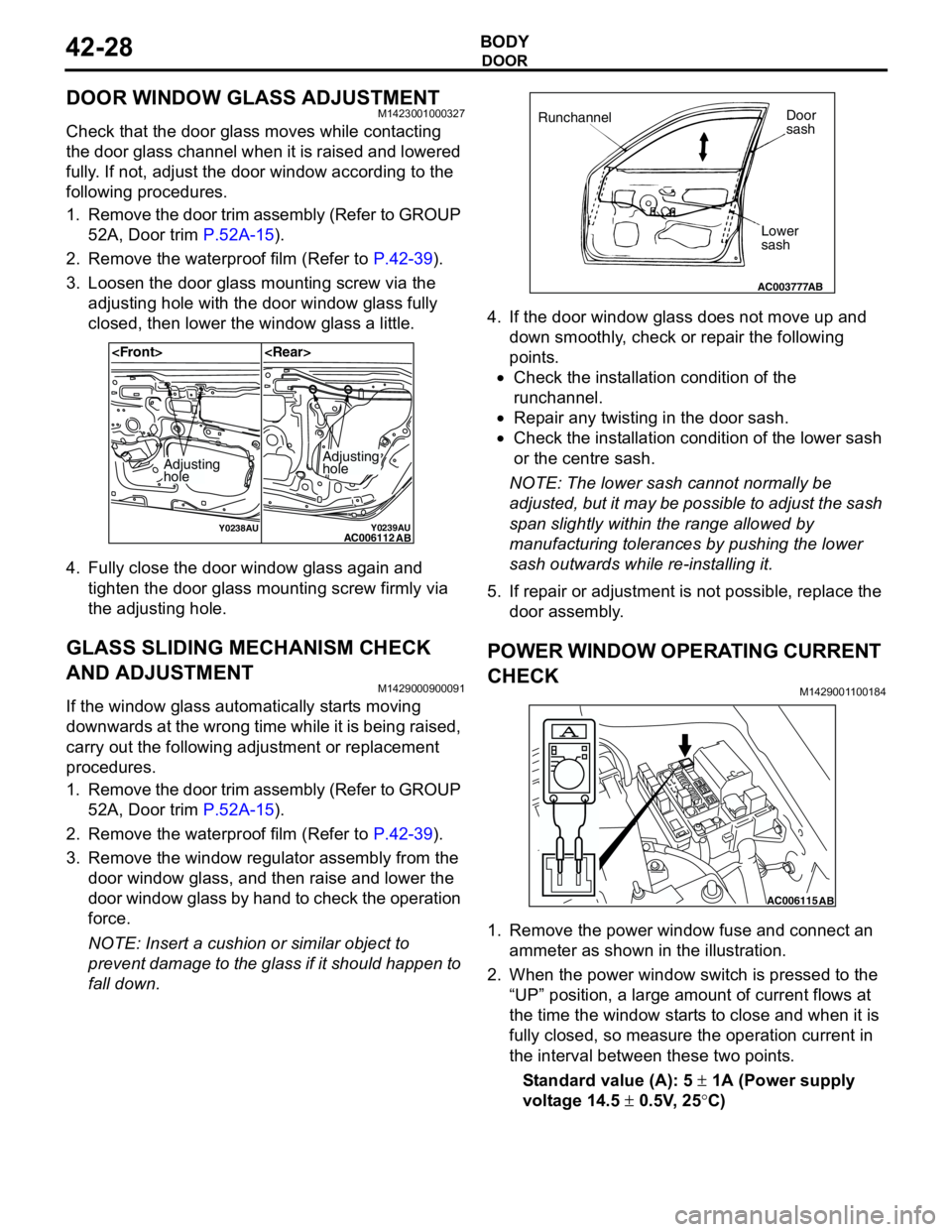
3. Loosen the door glass mounting screw via the
adjusting hole with the door window glass fully
closed, then lower the window glass a little.
4. Fully close the door window glass again and
tighten the door glass mounting screw firmly via
the adjusting hole.
GLASS SLIDING MECHANISM CHECK
AND ADJUSTMENT
M1429000900091
If the window glass automatically starts moving
downwards at the wrong time while it is being raised,
carry out the following adjustment or replacement
procedures.
1. Remove the door trim assembly (Refer to GROUP
52A, Door trim P.52A-15).
2. Remove the waterproof film (Refer to P.42-39).
3. Remove the window regulator assembly from the
door window glass, and then raise and lower the
door window glass by hand to check the operation
force.
NOTE: Insert a cushion or similar object to
prevent damage to the glass if it should happen to
fall down.4. If the door window glass does not move up and
down smoothly, check or repair the following
points.
•Check the installation condition of the
runchannel.
•Repair any twisting in the door sash.
•Check the installation condition of the lower sash
or the centre sash.
NOTE: The lower sash cannot normally be
adjusted, but it may be possible to adjust the sash
span slightly within the range allowed by
manufacturing tolerances by pushing the lower
sash outwards while re-installing it.
5. If repair or adjustment is not possible, replace the
door assembly.
POWER WINDOW OPERATING CURRENT
CHECK
M1429001100184
1. Remove the power window fuse and connect an
ammeter as shown in the illustration.
2. When the power window switch is pressed to the
“UP” position, a large amount of current flows at
the time the window starts to close and when it is
fully closed, so measure the operation current in
the interval between these two points.
Standard value (A): 5 ± 1A (Power supply
voltage 14.5 ± 0.5V, 25°C)
Y0238AUY0239AUAC006112
AB
Adjusting
holeAdjusting
hole
AC003777
RunchannelDoor
sash
Lower
sash
AB
AC006115AB
Page 313 of 788

DOOR
BODY42-35
CAUTION
The anti-trap function does not work until the
power window switch completes learning the
fully closed position (It is because the anti-trap
function is reset).
3. Operate the power window switch and fully close
the door window glass. The power window
activates for 0.7 seconds and stops automatically
when the power window switch is pressed once.
Repeat this operation until the door window glass
fully closes and release the switch once. Then,
hold the power window switch to the fully closed
side again for one second so that the power
window switch completes learning the fully closed
position.
NOTE: If the power window switch is operated to
open the door window glass while the switch is
learning, learning will be cancelled. If this
happens, return to step 2.
How to make the power window switch
learn the fully closed position when the
power window switch is replaced with a
new one
CAUTION
The anti-trap function does not work until the
power window switch completes learning the
fully closed position (It is because the anti-trap
function is reset).
Operate the power window main switch to fully close
the door window glass by one-shot up action so that
the power window switch will complete learning
(Initialisation is not needed).
NOTE: When the power window sub switch of each
seat is replaced, operate the power window main
switch to fully close the applicable power window by
one-shot up action (It is because the power window
sub switch does not have one-shot up/down
function).
Page 332 of 788
KEYLESS ENTRY SYSTEM
BODY42-54
•Enable the hazard answerback function
when the doors are locked: The
ETACS-ECU buzzer will sound once.
•Disable the hazard answerback function
when the doors are locked: The
ETACS-ECU buzzer will sound twice.
3. If the transmitter “UNLOCK” button is pushed
consecutively twice (within two seconds), the
ETACS-ECU buzzer will sound, indicating that the
hazard answerback function can be enabled or
disabled when the doors are unlocked.
•Enable the hazard answerback function
when the doors are unlocked: The
ETACS-ECU buzzer will sound once.
•Disable the hazard answerback function
when the doors are unlocked: The
ETACS-ECU buzzer will sound twice.
4. Exit the hazard answerback customize mode by
observing one of the following steps.
(1) Disconnect diagnosis connector terminal (1)
form the earth.
(2) Turn the ignition switch to position other then
“LOCK”(OFF), or remove the ignition key.
(3) Open the driver's side door.
(4) Any other warning buzzer output occurs.
NOTE: If any operation is not done for at least three
minutes after the ETACS-ECU has entered the
customize mode, the hazard answerback customize
mode will be canceled automatically.
connector>
1. Enter the hazard answerback customize mode by
performing one of the following steps. If the
ETACS-ECU enters the customize mode, its
buzzer will sound once.
(1) Turn the ignition switch to “LOCK”(OFF)
position.
(2) Turn off the hazard warning lamp switch.
CAUTION
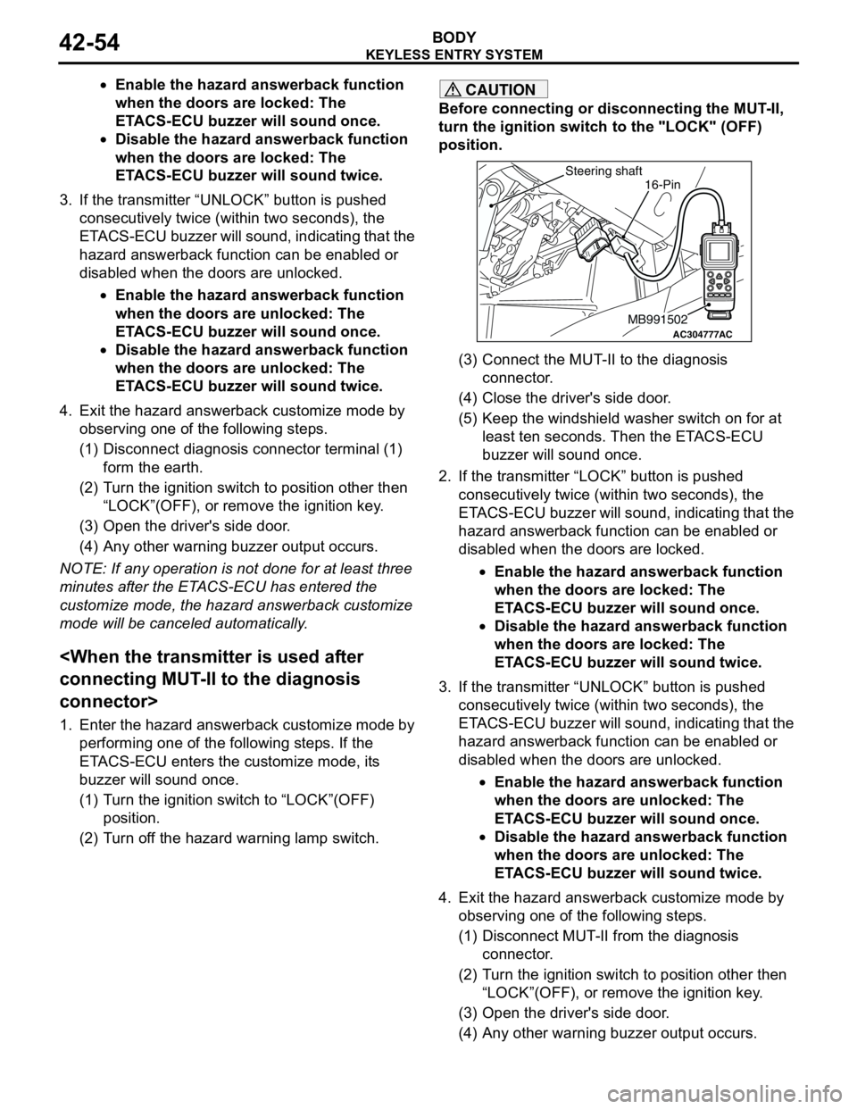
Before connecting or disconnecting the MUT-II,
turn the ignition switch to the "LOCK" (OFF)
position.
(3) Connect the MUT-II to the diagnosis
connector.
(4) Close the driver's side door.
(5) Keep the windshield washer switch on for at
least ten seconds. Then the ETACS-ECU
buzzer will sound once.
2. If the transmitter “LOCK” button is pushed
consecutively twice (within two seconds), the
ETACS-ECU buzzer will sound, indicating that the
hazard answerback function can be enabled or
disabled when the doors are locked.
•Enable the hazard answerback function
when the doors are locked: The
ETACS-ECU buzzer will sound once.
•Disable the hazard answerback function
when the doors are locked: The
ETACS-ECU buzzer will sound twice.
3. If the transmitter “UNLOCK” button is pushed
consecutively twice (within two seconds), the
ETACS-ECU buzzer will sound, indicating that the
hazard answerback function can be enabled or
disabled when the doors are unlocked.
•Enable the hazard answerback function
when the doors are unlocked: The
ETACS-ECU buzzer will sound once.
•Disable the hazard answerback function
when the doors are unlocked: The
ETACS-ECU buzzer will sound twice.
4. Exit the hazard answerback customize mode by
observing one of the following steps.
(1) Disconnect MUT-II from the diagnosis
connector.
(2) Turn the ignition switch to position other then
“LOCK”(OFF), or remove the ignition key.
(3) Open the driver's side door.
(4) Any other warning buzzer output occurs.
AC304777
Steering shaft
ACMB991502
16-Pin
Page 333 of 788
KEYLESS ENTRY SYSTEM
BODY42-55
NOTE: If any operation is not done for at least three
minutes after the ETACS-ECU has entered the
customize mode, the hazard answerback customize
mode will be canceled automatically.
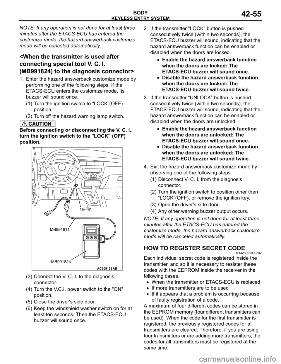
(MB991824) to the diagnosis connector>
1. Enter the hazard answerback customize mode by
performing one of the following steps. If the
ETACS-ECU enters the customize mode, its
buzzer will sound once.
(1) Turn the ignition switch to “LOCK”(OFF)
position.
(2) Turn off the hazard warning lamp switch.
CAUTION
Before connecting or disconnecting the V. C. I.,
turn the ignition switch to the "LOCK" (OFF)
position.
(3) Connect the V. C. I. to the diagnosis
connector.
(4) Turn the V.C.I. power switch to the "ON"
position.
(5) Close the driver's side door.
(6) Keep the windshield washer switch on for at
least ten seconds. Then the ETACS-ECU
buzzer will sound once.2. If the transmitter “LOCK” button is pushed
consecutively twice (within two seconds), the
ETACS-ECU buzzer will sound, indicating that the
hazard answerback function can be enabled or
disabled when the doors are locked.
•Enable the hazard answerback function
when the doors are locked: The
ETACS-ECU buzzer will sound once.
•Disable the hazard answerback function
when the doors are locked: The
ETACS-ECU buzzer will sound twice.
3. If the transmitter “UNLOCK” button is pushed
consecutively twice (within two seconds), the
ETACS-ECU buzzer will sound, indicating that the
hazard answerback function can be enabled or
disabled when the doors are unlocked.
•Enable the hazard answerback function
when the doors are unlocked: The
ETACS-ECU buzzer will sound once.
•Disable the hazard answerback function
when the doors are unlocked: The
ETACS-ECU buzzer will sound twice.
4. Exit the hazard answerback customize mode by
observing one of the following steps.
(1) Disconnect V. C. I. from the diagnosis
connector.
(2) Turn the ignition switch to position other then
“LOCK”(OFF), or remove the ignition key.
(3) Open the driver's side door.
(4) Any other warning buzzer output occurs.
NOTE: If any operation is not done for at least three
minutes after the ETACS-ECU has entered the
customize mode, the hazard answerback customize
mode will be canceled automatically.
HOW TO REGISTER SECRET CODEM1428001000292
Each individual secret code is registered inside the
transmitter, and so it is necessary to resister these
codes with the EEPROM inside the receiver in the
following cases.
•When the transmitter or ETACS-ECU is replaced
•If more transmitters are to be used
•If it appears that a problem is occurring because
of faulty registration of a code.
A maximum of four different codes can be stored in
the EEPROM memory (four different transmitters can
be used). When the code for the first transmitter is
registered, the previously registered codes for all
transmitters are cleared. Therefore, if you are using
four transmitters or are adding more transmitters, the
codes for all transmitters must be registered at the
same time.
AC305153AB
MB991911
MB991824
16-Pin
Page 363 of 788
WINDSHIELD WIPER AND WASHER
EXTERIOR51-25
INSPECTIONM1511007700313
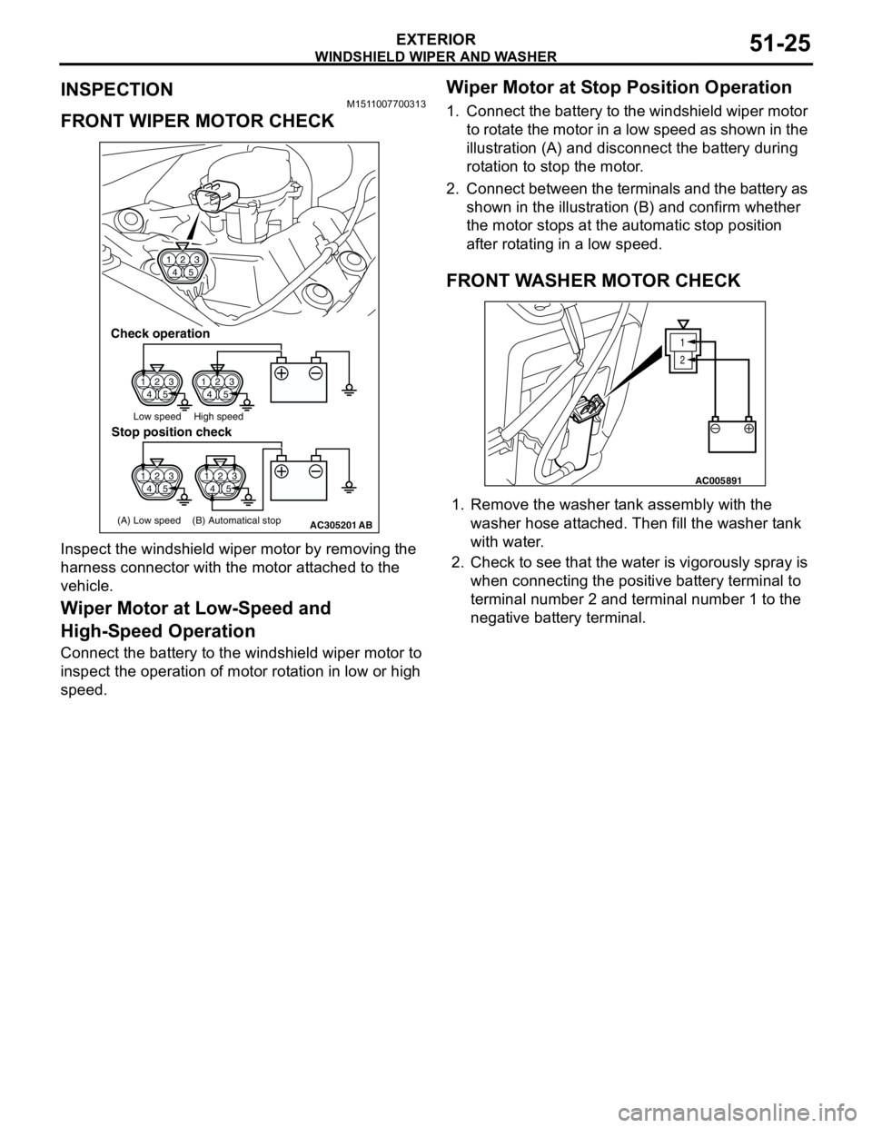
FRONT WIPER MOTOR CHECK
Inspect the windshield wiper motor by removing the
harness connector with the motor attached to the
vehicle.
Wiper Motor at Low-Speed and
High-Speed Operation
Connect the battery to the windshield wiper motor to
inspect the operation of motor rotation in low or high
speed.
Wiper Motor at Stop Position Operation
1. Connect the battery to the windshield wiper motor
to rotate the motor in a low speed as shown in the
illustration (A) and disconnect the battery during
rotation to stop the motor.
2. Connect between the terminals and the battery as
shown in the illustration (B) and confirm whether
the motor stops at the automatic stop position
after rotating in a low speed.
FRONT WASHER MOTOR CHECK
1. Remove the washer tank assembly with the
washer hose attached. Then fill the washer tank
with water.
2. Check to see that the water is vigorously spray is
when connecting the positive battery terminal to
terminal number 2 and terminal number 1 to the
negative battery terminal.
1
423
5
1
423
51
423
5
1
423
5
AC305201
1
423
5
Check operation
Low speed High speed
(A) Low speed (B) Automatical stop
Stop position check
AB
1
2
AC005891
Page 368 of 788
REAR WIPER AND WASHER
EXTERIOR51-30
INSTALLATION SERVICE POINTS
>>A<< REAR WIPER ARM AND BLADE
ASSEMBLY INSTALLATION
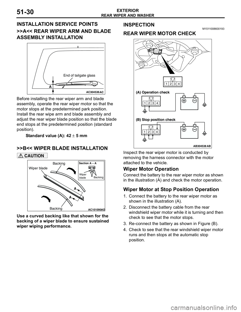
Before installing the rear wiper arm and blade
assembly, operate the rear wiper motor so that the
motor stops at the predetermined park position.
Install the rear wipe arm and blade assembly and
adjust the rear wiper blade position so that the blade
end stops at the predetermined position (standard
position).
Standard value (A): 42 ± 5 mm
>>B<< WIPER BLADE INSTALLATION
CAUTION
Use a curved backing like that shown for the
backing of a wiper blade to ensure sustained
wiper wiping performance.
INSPECTIONM1511008600193
REAR WIPER MOTOR CHECK
Inspect the rear wiper motor is conducted by
removing the harness connector with the motor
attached to the vehicle.
Wiper Motor Operation
Connect the battery to the rear wiper motor as shown
in the illustration (A) and check the motor operation.
Wiper Motor at Stop Position Operation
1. Connect the battery to the rear wiper motor as
shown in the illustration (A).
2. Disconnect the battery cable from the rear
windshield wiper motor while it is turning and then
check to see that the motor stops.
3. Re-connect the battery as shown in Figure (B).
4. Check to see that the rear windshield wiper motor
runs and then stops at the automatic stop
position.
AC304536
A
AC
End of tailgate glass
AC101090AD
Wiper bladeBacking
BackingA
A
Section A – A
Wiper
bladeBacking
AB304538
1234
1234
1234
AB
(A) Operation check
(B) Stop position check
Page 374 of 788
DOOR MIRROR
EXTERIOR51-36
DOOR MIRROR
GENERAL INFORMATIONM1511000100536
DOOR MIRROR OPERATION
Remote Controlled Mirror Operation
•The mirror on the door mirror moves up/down
and left/right by operating the remote controlled
door mirror switch when the ignition switch is in
the "ON" or "ACC" position.Heated Door Mirror operation
•The defogger relay switch is activated (ON) by
turning on the A/C-ECU built-in defogger switch
when the ignition switch is in the "ON" position.
When the defogger relay is turned ON, power is
supplied to the defogger and door mirror, and the
heater of the door mirror (heated door mirror)
starts operations. The defogger comes with a
timer function and will automatically turn OFF the
switch approximately 11 minutes after the
defogger switch is turned ON. The heated door
mirror operations are also terminated along with
the defogger, at this time.
SERVICE SPECIFICATIONM1511000300347
SPECIAL TOOLM1511000601103
TROUBLESHOOTING
DIAGNOSIS TROUBLESHOOTING FLOWM1511014600169
Refer to GROUP 00 − How to Use
Troubleshooting/Inspection Service Points P.00-5.
TROUBLE SYMPTOM CHARTM1511015000160
ItemStandard value
Heated door mirror operation current Ω5.9 − 7.8
Tool Number Name Application
MB990784 Ornament remover Removal of remote controlled
mirror switch
MB990784
Symptom Inspection
procedureReference
page
All heated door mirrors do not operate 1
P.51-37
The right or left heated door mirror does not operate 2
P.51-39