wheel size MITSUBISHI LANCER 2005 Workshop Manual
[x] Cancel search | Manufacturer: MITSUBISHI, Model Year: 2005, Model line: LANCER, Model: MITSUBISHI LANCER 2005Pages: 788, PDF Size: 45.98 MB
Page 164 of 788

GENERAL INFORMATION
WHEEL AND TYRE31-2
GENERAL INFORMATION
M1311000100220The wheels and tyres of the following specifications
have been established.
SPECIFICATIONS
ROAD WHEEL AND TYRE
SPARE WHEEL AND TYRE
NOTE: .
•The * mark indicates optional item.
•PCD (Pitch Circle Diameter) indicates the pitch circle diameter of the wheel installation holes.
SERVICE SPECIFICATIONS
M1311000300398
Item Comfort Sport
Wheel Type Steel type or Aluminium type* Aluminium type
Size 15 × 6JJ 16 × 6JJ
Amount of wheel offset mm 46 46
PCD mm 114.3 114.3
Tyre Size 195/60R15 88H 195/50R16 84V
Item Comfort Sport
Spare
wheelType Steel type Steel type
Size 16 × 4T or 15 × 6JJ* 16 × 4T or 16 × 6JJ*
Amount of wheel offset mm 46 40 or 46*
PCD mm 114.3 114.3
Spare tyre Size T125/70D16 96M or
195/60R15 88H*T125/70D16 96M or
195/50R16 84V*
ITEM LIMIT
Tread depth of tyre mm Minimum 1.6
Wheel runout
Lateral runout mm 1.0 or less
Wheel runout
Lateral runout mm 1.2 or less
Page 166 of 788

TROUBLESHOOTING
WHEEL AND TYRE31-4
WHEEL BALANCE ACCURACYM1311001700247
PURPOSE
This section contains tips and procedures for
achieving accurate wheel balance. Steering wheel
vibration and/or body shake can result if any of these
procedures are not carefully observed.
1. Wheels and tyres must be properly mounted on a
balancer in order to achieve correct balance.
Centring the wheel on the shaft of the balancer is
essential for proper mounting.
2. Off-the-car wheel balancers must be calibrated
periodically to ensure good balancing results. An
inaccurately calibrated balancer could cause
unnecessary replacement of tyres, shocks,
suspension components, or steering components.
Check your balancer's calibration approximately
every 100 balances. Your wheel balancer's
instruction manual should include calibration
procedures. If the calibration procedures specifically
for your balancer are missing, use the generic steps
in this section for zero calibration, static balance, and
dynamic balance checks. The wheel balancer
calibration checks are also described in the
flowchart. (Refer to P.31-6).
PROCEDURE
1. Confirm that the balancer's cone and the wheel
mounting cone are undamaged and free of dirt
and rust.
2. On this vehicle, the wheel's centre hole on the
hub side has a chamfered edge. Use a
back-mounting cone on your wheel balancer to
centre the wheel on the balancer shaft.
3. Install a wheel mounting cone. The appropriate
size cone for this vehicle is 67.0 mm.
4. Before balancing the wheel, remove any wheel
weights from both sides. Also check both sides for
any damage.
5. When installing wheel weights, hammer them at a
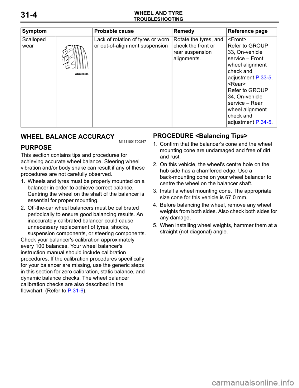
straight (not diagonal) angle. Scalloped
wearLack of rotation of tyres or worn
or out-of-alignment suspensionRotate the tyres, and
check the front or
rear suspension
alignments.
Refer to GROUP
33, On-vehicle
service − Front
wheel alignment
check and
adjustment P.33-5.
Refer to GROUP
34, On-vehicle
service − Rear
wheel alignment
check and
adjustment P.34-5. Symptom Probable cause Remedy Reference page
ACX00934
Page 448 of 788

COMBINATION METER ASSEMBLY
CHASSIS ELECTRICAL54A-60
STEP 9. Check the wiring harness between
combination meter connector C-04 (terminal 1
and 2) and earth.
Q: Are the wiring harness between combination meter
connector C-04 (terminal 1 and 2) and earth in
good condition?
YES :
This procedure is complete.
NO : Repair or replace the wiring harness. Check
to see that all meters operate.
ON-VEHICLE SERVICE
SPEEDOMETER CHECKM1543000900423
Adjust the pressure of tyres to the specified level.
(Refer to GROUP 31, On-vehicle Service P.31-7.)
CAUTION
Do not operate the clutch suddenly. Do not
increase/decrease speed rapidly while testing.
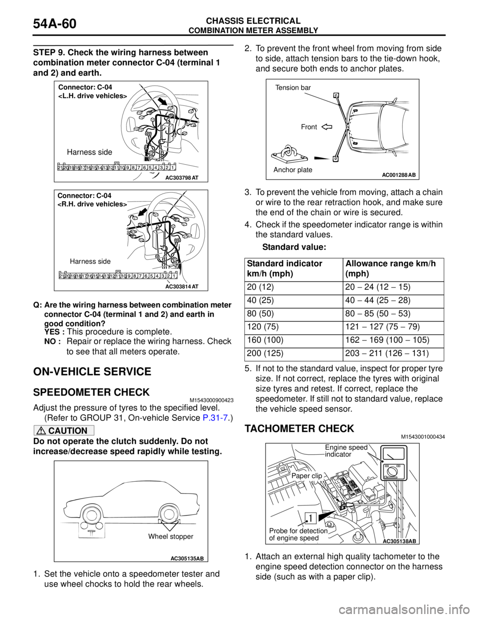
1. Set the vehicle onto a speedometer tester and
use wheel chocks to hold the rear wheels.2. To prevent the front wheel from moving from side
to side, attach tension bars to the tie-down hook,
and secure both ends to anchor plates.
3. To prevent the vehicle from moving, attach a chain
or wire to the rear retraction hook, and make sure
the end of the chain or wire is secured.
4. Check if the speedometer indicator range is within
the standard values.
Standard value:
5. If not to the standard value, inspect for proper tyre
size. If not correct, replace the tyres with original
size tyres and retest. If correct, replace the
speedometer. If still not to standard value, replace
the vehicle speed sensor.
TACHOMETER CHECKM1543001000434
1. Attach an external high quality tachometer to the
engine speed detection connector on the harness
side (such as with a paper clip).
AC303798
Connector: C-04
Harness side
AT
AC303814
Connector: C-04
Harness side
AT
AC305135AB
Wheel stopper
Standard indicator
km/h (mph)Allowance range km/h
(mph)
20 (12) 20 − 24 (12 − 15)
40 (25) 40 − 44 (25 − 28)
80 (50) 80 − 85 (50 − 53)
120 (75) 121 − 127 (75 − 79)
160 (100) 162 − 169 (100 − 105)
200 (125) 203 − 211 (126 − 131)
AC001288
Tension bar
Front
Anchor plate
AB
AC305138AB
Engine speed
indicator
Paper clip
Probe for detection
of engine speed