Engine controls MITSUBISHI LANCER 2005 Workshop Manual
[x] Cancel search | Manufacturer: MITSUBISHI, Model Year: 2005, Model line: LANCER, Model: MITSUBISHI LANCER 2005Pages: 788, PDF Size: 45.98 MB
Page 21 of 788

TROUBLESHOOTING
ENGINE COOLING14-7
CIRCUIT OPERATION
•The cooling fan motor drive control unit is
powered from fusible link (2).
•The engine-ECU
uses input signals from the A/C switch, the
water temperature sensor unit and the vehicle
speed sensor
sensor to control the speed of the cooling
fan motor (L.H.) and the cooling fan motor (R.H.)
<4G1 (Vehicles with A/C)> or A/C condenser fan
motor <4G6>.
•The engine-ECU
controls the cooling fan motor drive control
unit to activate the cooling fan motor (L.H.) and
the cooling fan motor (R.H.) <4G1 (Vehicles with
A/C)> or A/C condenser fan motor <4G6>.
TECHNICAL DESCRIPTION
•The cause could be a malfunction of the cooling
fan motor drive control unit power supply or earth
circuit.
•If the communication line wiring harness between
the cooling fan motor drive control unit and the
engine-ECU
short-circuited to earth, the cooling fan motor
(L.H.) and the cooling fan motor (R.H.) <4G1
(Vehicles with A/C)> or the A/C condenser fan
motor <4G6> will not rotate.
•The cause could also be a malfunction of the
cooling fan motor (L.H.).
•The cause could also be a malfunction of imput
signal from the A/C switch, the water temperature
sensor unit and the vehicle speed sensor
or the output shaft speed sensor to the
engine-ECU
•The cause could also be a malfunction of the
cooling fan motor drive control unit or the
engine-ECU
TROUBLESHOOTING HINTS
•Malfunction of fusible link (2)
•Malfunction of fan control relay
•Malfunction of cooling fan motor (L.H.)
•Malfunction of cooling fan motor drive control unit
•Malfunction of engine-ECU
engine-A/T-ECU
•Damaged wiring harness or connector
DIAGNOSIS
STEP 1. Check the cooling fan motor (L.H.).
Refer to P.14-25.
Q: Is the cooling fan motor (L.H.) in good condition?
YES :
Go to Step 2 .
NO : Replace the cooling fan motor (L.H.) (Refer
to P.14-35). Then go to Step 24 .
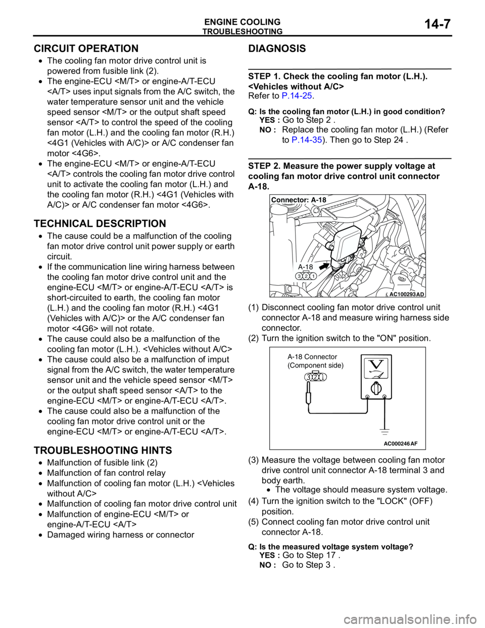
STEP 2. Measure the power supply voltage at
cooling fan motor drive control unit connector
A-18.
(1) Disconnect cooling fan motor drive control unit
connector A-18 and measure wiring harness side
connector.
(2) Turn the ignition switch to the "ON" position.
(3) Measure the voltage between cooling fan motor
drive control unit connector A-18 terminal 3 and
body earth.
•The voltage should measure system voltage.
(4) Turn the ignition switch to the "LOCK" (OFF)
position.
(5) Connect cooling fan motor drive control unit
connector A-18.
Q: Is the measured voltage system voltage?
YES :
Go to Step 17 .
NO : Go to Step 3 .
AC100293
A-18
321
Connector: A-18
AD
AC000246AF
A-18 Connector
(Component side)
Page 557 of 788

ON-VEHICLE SERVICE
HEATER, AIR CONDITIONER AND VENTILATION55-73
PERFORMANCE TEST M1552001400355
1. The vehicles to be tested should be in a place that
is not in direct sunlight.
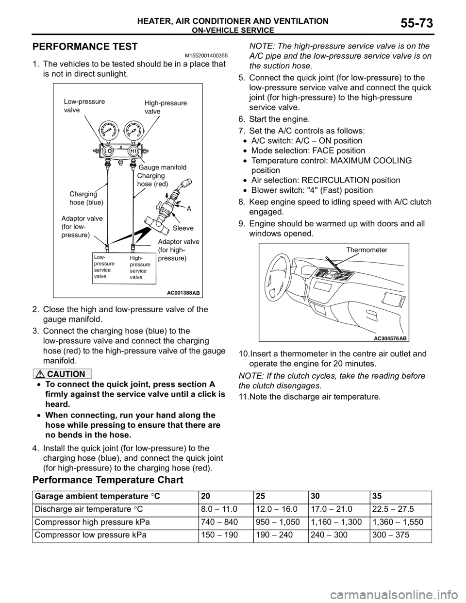
2. Close the high and low-pressure valve of the
gauge manifold.
3. Connect the charging hose (blue) to the
low-pressure valve and connect the charging
hose (red) to the high-pressure valve of the gauge
manifold.
CAUTION
•To connect the quick joint, press section A
firmly against the service valve until a click is
heard.
•When connecting, run your hand along the
hose while pressing to ensure that there are
no bends in the hose.
4. Install the quick joint (for low-pressure) to the
charging hose (blue), and connect the quick joint
(for high-pressure) to the charging hose (red).NOTE: The high-pressure service valve is on the
A/C pipe and the low-pressure service valve is on
the suction hose.
5. Connect the quick joint (for low-pressure) to the
low-pressure service valve and connect the quick
joint (for high-pressure) to the high-pressure
service valve.
6. Start the engine.
7. Set the A/C controls as follows:
•A/C switch: A/C − ON position
•Mode selection: FACE position
•Temperature control: MAXIMUM COOLING
position
•Air selection: RECIRCULATION position
•Blower switch: "4" (Fast) position
8. Keep engine speed to idling speed with A/C clutch
engaged.
9. Engine should be warmed up with doors and all
windows opened.
10.Insert a thermometer in the centre air outlet and
operate the engine for 20 minutes.
NOTE: If the clutch cycles, take the reading before
the clutch disengages.
11.Note the discharge air temperature.
Performance Temperature Chart
AC001388
Low-pressure
valveHigh-pressure
valve
Gauge manifold
Charging
hose (red)
A
Sleeve Charging
hose (blue)
Adaptor valve
(for low-
pressure)
Low-
pressure
service
valveHigh-
pressure
service
valve
AB
Adaptor valve
(for high-
pressure)
AC304576
Thermometer
AB
Garage ambient temperature °C20 25 30 35
Discharge air temperature °C8.0 − 11.0 12.0 − 16.0 17.0 − 21.0 22.5 − 27.5
Compressor high pressure kPa 740 − 840 950 − 1,050 1,160 − 1,300 1,360 − 1,550
Compressor low pressure kPa 150 − 190 190 − 240 240 − 300 300 − 375