ignition MITSUBISHI LANCER 2005 Workshop Manual
[x] Cancel search | Manufacturer: MITSUBISHI, Model Year: 2005, Model line: LANCER, Model: MITSUBISHI LANCER 2005Pages: 788, PDF Size: 45.98 MB
Page 21 of 788
TROUBLESHOOTING
ENGINE COOLING14-7
CIRCUIT OPERATION
•The cooling fan motor drive control unit is
powered from fusible link (2).
•The engine-ECU
uses input signals from the A/C switch, the
water temperature sensor unit and the vehicle
speed sensor
sensor to control the speed of the cooling
fan motor (L.H.) and the cooling fan motor (R.H.)
<4G1 (Vehicles with A/C)> or A/C condenser fan
motor <4G6>.
•The engine-ECU
controls the cooling fan motor drive control
unit to activate the cooling fan motor (L.H.) and
the cooling fan motor (R.H.) <4G1 (Vehicles with
A/C)> or A/C condenser fan motor <4G6>.
TECHNICAL DESCRIPTION
•The cause could be a malfunction of the cooling
fan motor drive control unit power supply or earth
circuit.
•If the communication line wiring harness between
the cooling fan motor drive control unit and the
engine-ECU
short-circuited to earth, the cooling fan motor
(L.H.) and the cooling fan motor (R.H.) <4G1
(Vehicles with A/C)> or the A/C condenser fan
motor <4G6> will not rotate.
•The cause could also be a malfunction of the
cooling fan motor (L.H.).
•The cause could also be a malfunction of imput
signal from the A/C switch, the water temperature
sensor unit and the vehicle speed sensor
or the output shaft speed sensor to the
engine-ECU
•The cause could also be a malfunction of the
cooling fan motor drive control unit or the
engine-ECU
TROUBLESHOOTING HINTS
•Malfunction of fusible link (2)
•Malfunction of fan control relay
•Malfunction of cooling fan motor (L.H.)
•Malfunction of cooling fan motor drive control unit
•Malfunction of engine-ECU
engine-A/T-ECU
•Damaged wiring harness or connector
DIAGNOSIS
STEP 1. Check the cooling fan motor (L.H.).
Refer to P.14-25.
Q: Is the cooling fan motor (L.H.) in good condition?
YES :
Go to Step 2 .
NO : Replace the cooling fan motor (L.H.) (Refer
to P.14-35). Then go to Step 24 .
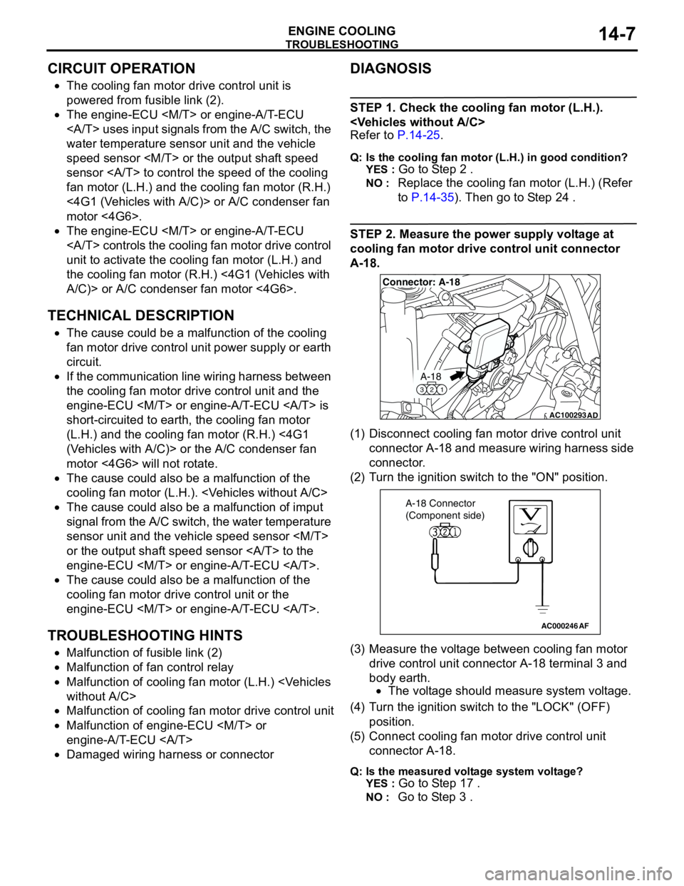
STEP 2. Measure the power supply voltage at
cooling fan motor drive control unit connector
A-18.
(1) Disconnect cooling fan motor drive control unit
connector A-18 and measure wiring harness side
connector.
(2) Turn the ignition switch to the "ON" position.
(3) Measure the voltage between cooling fan motor
drive control unit connector A-18 terminal 3 and
body earth.
•The voltage should measure system voltage.
(4) Turn the ignition switch to the "LOCK" (OFF)
position.
(5) Connect cooling fan motor drive control unit
connector A-18.
Q: Is the measured voltage system voltage?
YES :
Go to Step 17 .
NO : Go to Step 3 .
AC100293
A-18
321
Connector: A-18
AD
AC000246AF
A-18 Connector
(Component side)
Page 22 of 788
TROUBLESHOOTING
ENGINE COOLING14-8
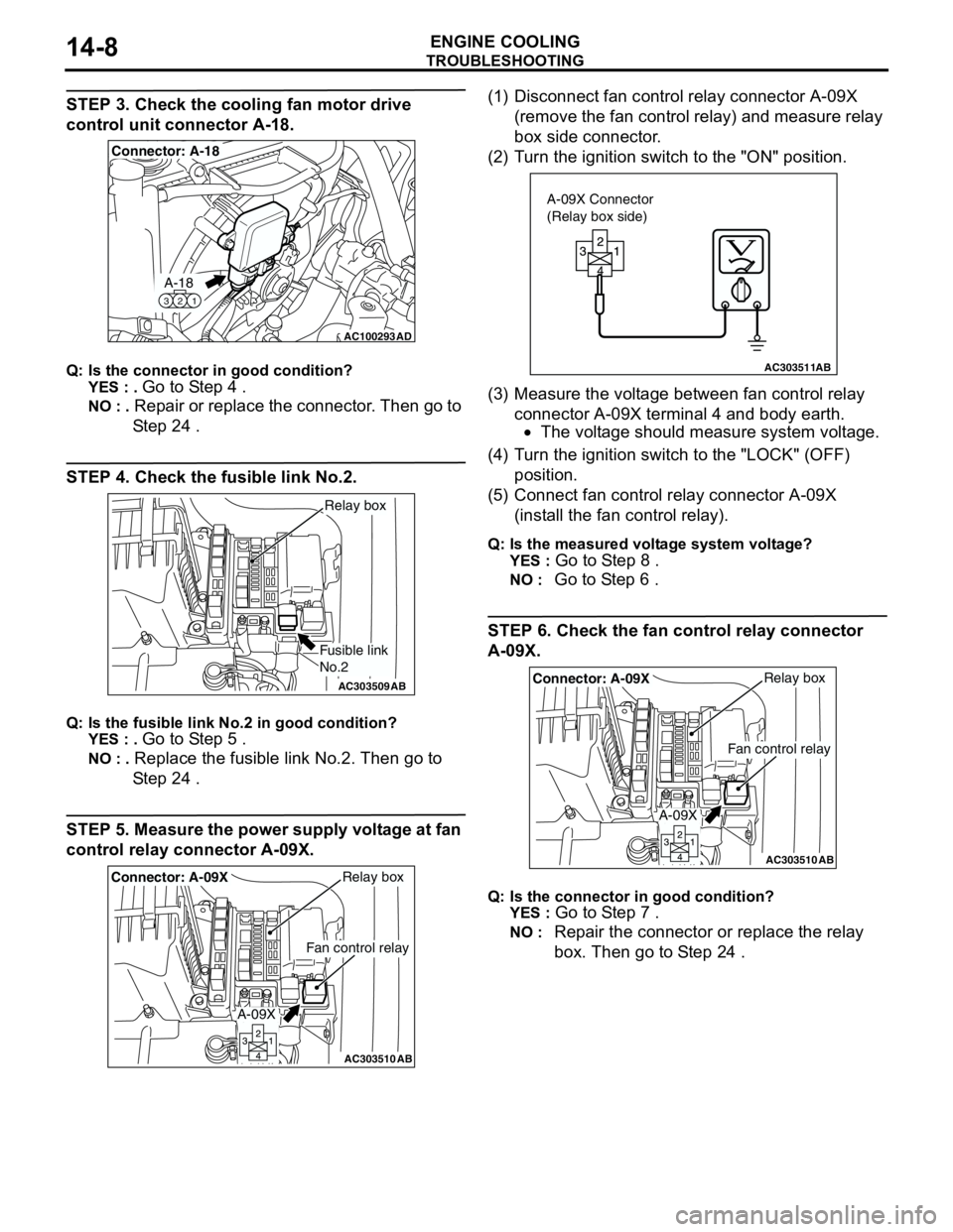
STEP 3. Check the cooling fan motor drive
control unit connector A-18.
Q: Is the connector in good condition?
YES : .
Go to Step 4 .
NO : . Repair or replace the connector. Then go to
Step 24 .
STEP 4. Check the fusible link No.2.
Q: Is the fusible link No.2 in good condition?
YES : .
Go to Step 5 .
NO : . Replace the fusible link No.2. Then go to
Step 24 .
STEP 5. Measure the power supply voltage at fan
control relay connector A-09X.(1) Disconnect fan control relay connector A-09X
(remove the fan control relay) and measure relay
box side connector.
(2) Turn the ignition switch to the "ON" position.
(3) Measure the voltage between fan control relay
connector A-09X terminal 4 and body earth.
•The voltage should measure system voltage.
(4) Turn the ignition switch to the "LOCK" (OFF)
position.
(5) Connect fan control relay connector A-09X
(install the fan control relay).
Q: Is the measured voltage system voltage?
YES :
Go to Step 8 .
NO : Go to Step 6 .
STEP 6. Check the fan control relay connector
A-09X.
Q: Is the connector in good condition?
YES :
Go to Step 7 .
NO : Repair the connector or replace the relay
box. Then go to Step 24 .
AC100293
A-18
321
Connector: A-18
AD
AC303509AB
Fusible link
No.2
Relay box
AC303510AB
Fan control relay
Relay boxConnector: A-09X
A-09X
AC303511AB
A-09X Connector
(Relay box side)
AC303510AB
Fan control relay
Relay boxConnector: A-09X
A-09X
Page 23 of 788
TROUBLESHOOTING
ENGINE COOLING14-9
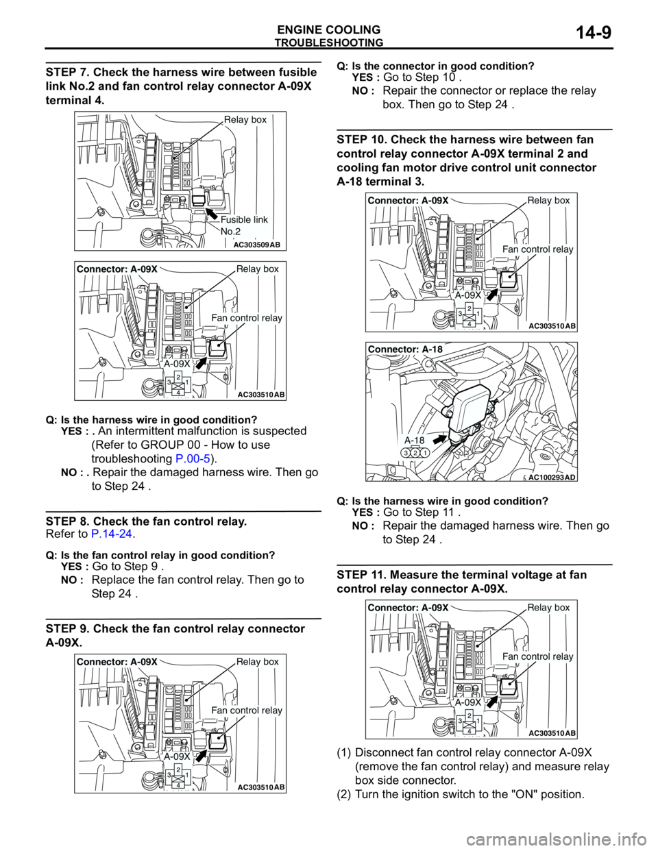
STEP 7. Check the harness wire between fusible
link No.2 and fan control relay connector A-09X
terminal 4.
Q: Is the harness wire in good condition?
YES : .
An intermittent malfunction is suspected
(Refer to GROUP 00 - How to use
troubleshooting P.00-5).
NO : . Repair the damaged harness wire. Then go
to Step 24 .
STEP 8. Check the fan control relay.
Refer to P.14-24.
Q: Is the fan control relay in good condition?
YES :
Go to Step 9 .
NO : Replace the fan control relay. Then go to
Step 24 .
STEP 9. Check the fan control relay connector
A-09X.
Q: Is the connector in good condition?
YES :
Go to Step 10 .
NO : Repair the connector or replace the relay
box. Then go to Step 24 .
STEP 10. Check the harness wire between fan
control relay connector A-09X terminal 2 and
cooling fan motor drive control unit connector
A-18 terminal 3.
Q: Is the harness wire in good condition?
YES :
Go to Step 11 .
NO : Repair the damaged harness wire. Then go
to Step 24 .
STEP 11. Measure the terminal voltage at fan
control relay connector A-09X.
(1) Disconnect fan control relay connector A-09X
(remove the fan control relay) and measure relay
box side connector.
(2) Turn the ignition switch to the "ON" position.
AC303509AB
Fusible link
No.2
Relay box
AC303510AB
Fan control relay
Relay boxConnector: A-09X
A-09X
AC303510AB
Fan control relay
Relay boxConnector: A-09X
A-09X
AC303510AB
Fan control relay
Relay boxConnector: A-09X
A-09X
AC100293
A-18
321
Connector: A-18
AD
AC303510AB
Fan control relay
Relay boxConnector: A-09X
A-09X
Page 24 of 788
TROUBLESHOOTING
ENGINE COOLING14-10
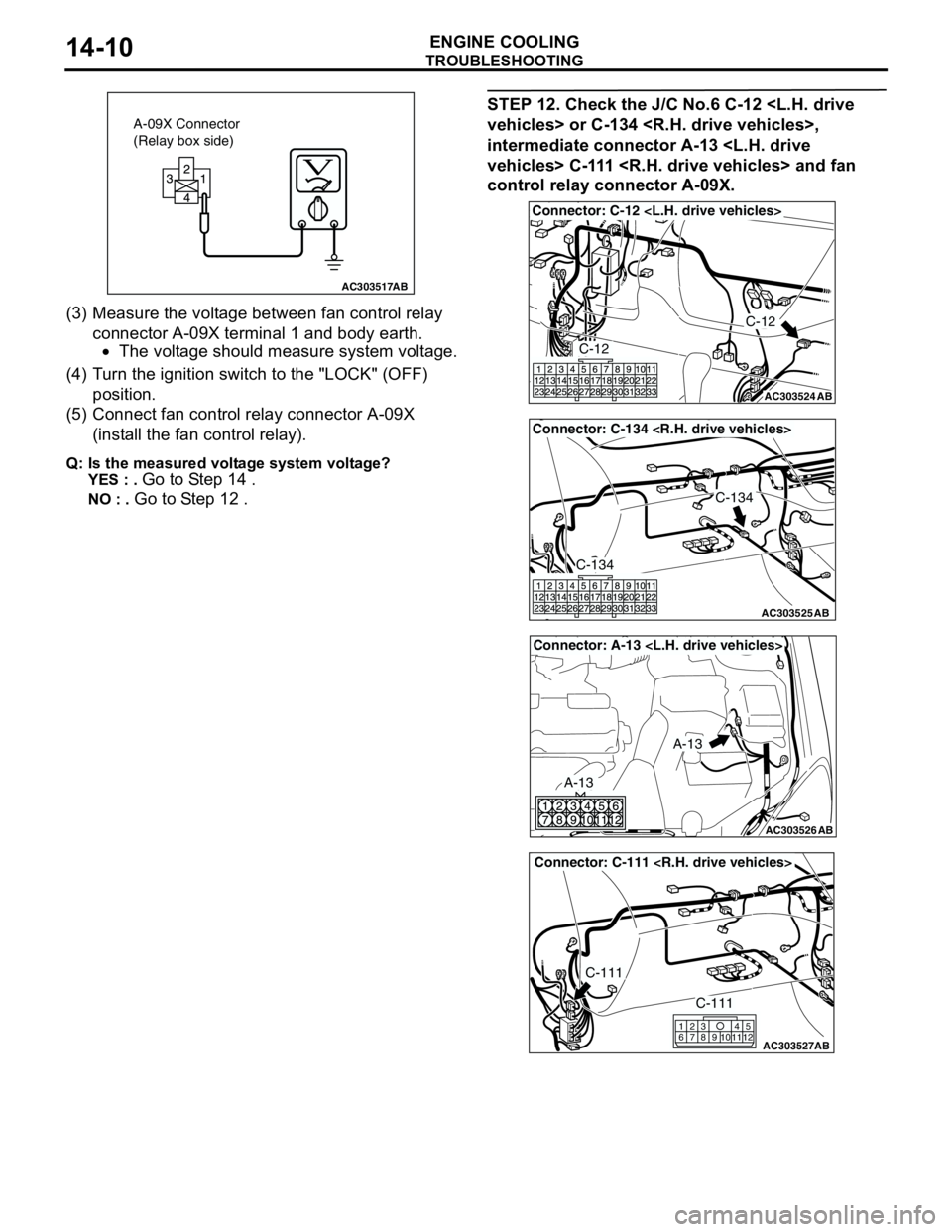
(3) Measure the voltage between fan control relay
connector A-09X terminal 1 and body earth.
•The voltage should measure system voltage.
(4) Turn the ignition switch to the "LOCK" (OFF)
position.
(5) Connect fan control relay connector A-09X
(install the fan control relay).
Q: Is the measured voltage system voltage?
YES : .
Go to Step 14 .
NO : . Go to Step 12 .
STEP 12. Check the J/C No.6 C-12
intermediate connector A-13
control relay connector A-09X.
AC303517AB
A-09X Connector
(Relay box side)
AC303524
Connector: C-12
AB
C-12
C-12
AC303525
Connector: C-134
AB
C-134
C-134
AC303526
Connector: A-13
AB
A-13
A-13
AC303527
Connector: C-111
AB
C-111
C-111
615
121179
810234
Page 29 of 788
TROUBLESHOOTING
ENGINE COOLING14-15
STEP 22. Check the cooling fan motor drive
control unit.
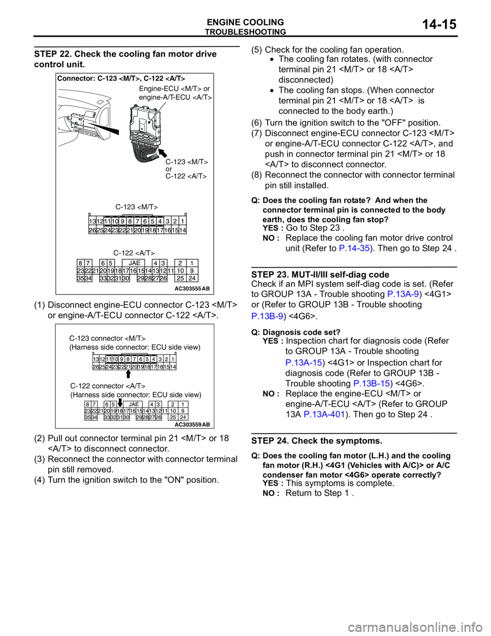
(1) Disconnect engine-ECU connector C-123
or engine-A/T-ECU connector C-122 .
(2) Pull out connector terminal pin 21
to disconnect connector.
(3) Reconnect the connector with connector terminal
pin still removed.
(4) Turn the ignition switch to the "ON" position.(5) Check for the cooling fan operation.
•The cooling fan rotates. (with connector
terminal pin 21
disconnected)
•The cooling fan stops. (When connector
terminal pin 21
connected to the body earth.)
(6) Turn the ignition switch to the "OFF" position.
(7) Disconnect engine-ECU connector C-123
or engine-A/T-ECU connector C-122 , and
push in connector terminal pin 21
to disconnect connector.
(8) Reconnect the connector with connector terminal
pin still installed.
Q: Does the cooling fan rotate? And when the
connector terminal pin is connected to the body
earth, does the cooling fan stop?
YES :
Go to Step 23 .
NO : Replace the cooling fan motor drive control
unit (Refer to P.14-35). Then go to Step 24 .
STEP 23. MUT-II/III self-diag code
Check if an MPI system self-diag code is set. (Refer
to GROUP 13A - Trouble shooting P.13A-9) <4G1>
or (Refer to GROUP 13B - Trouble shooting
P.13B-9) <4G6>.
Q: Diagnosis code set?
YES :
Inspection chart for diagnosis code (Refer
to GROUP 13A - Trouble shooting
P.13A-15) <4G1> or Inspection chart for
diagnosis code (Refer to GROUP 13B -
Trouble shooting P.13B-15) <4G6>.
NO : Replace the engine-ECU
engine-A/T-ECU (Refer to GROUP
13A P.13A-401). Then go to Step 24 .
STEP 24. Check the symptoms.
Q: Does the cooling fan motor (L.H.) and the cooling
fan motor (R.H.) <4G1 (Vehicles with A/C)> or A/C
condenser fan motor <4G6> operate correctly?
YES :
This symptoms is complete.
NO : Return to Step 1 .
AC303555AB
Connector: C-123
C-123
or
C-122
C-123
Engine-ECU
engine-A/T-ECU
C-122
AC303559
C-122 connector
(Harness side connector: ECU side view)
AB
C-123 connector
(Harness side connector: ECU side view)
Page 33 of 788
TROUBLESHOOTING
ENGINE COOLING14-19
STEP 6. Check the cooling fan motor drive
control unit.
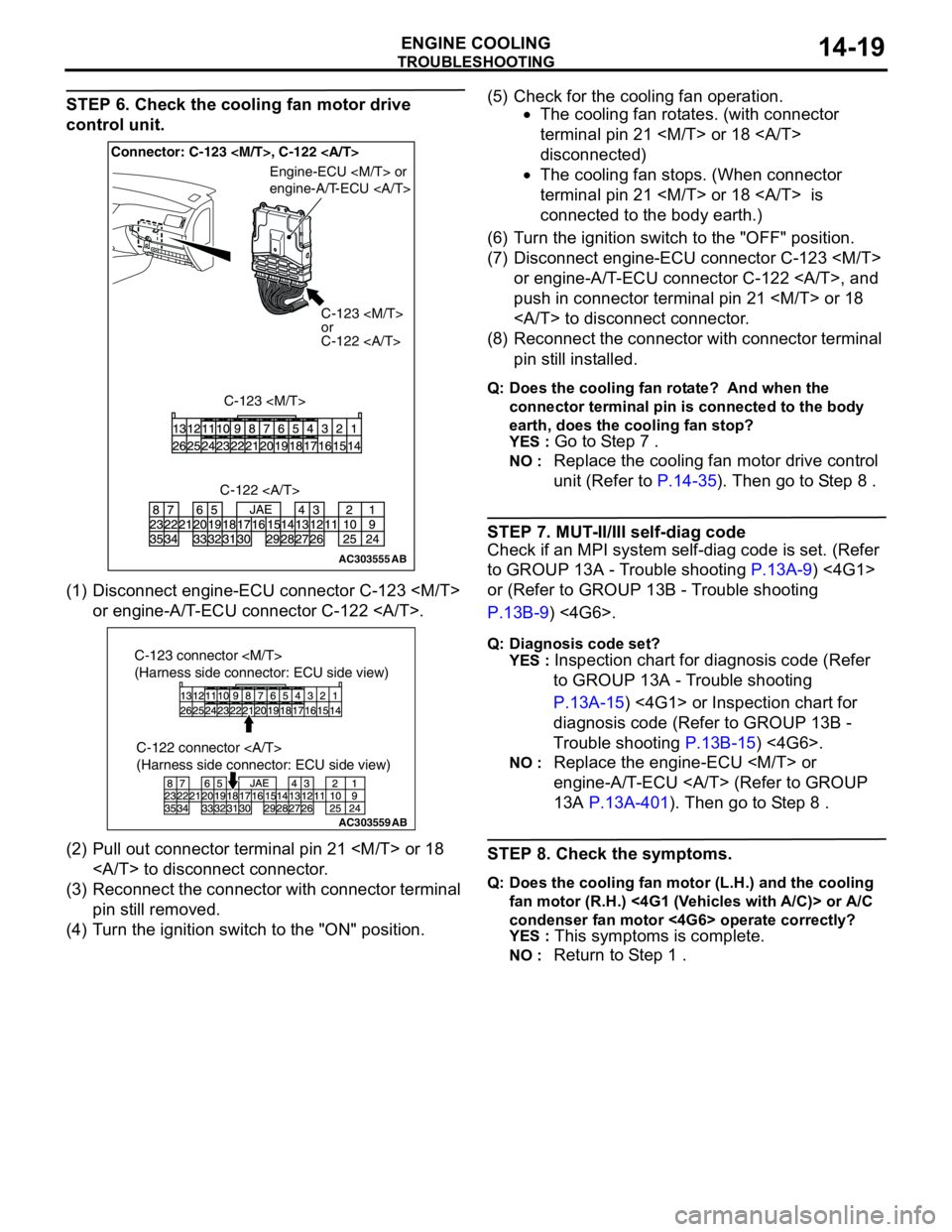
(1) Disconnect engine-ECU connector C-123
or engine-A/T-ECU connector C-122 .
(2) Pull out connector terminal pin 21
to disconnect connector.
(3) Reconnect the connector with connector terminal
pin still removed.
(4) Turn the ignition switch to the "ON" position.(5) Check for the cooling fan operation.
•The cooling fan rotates. (with connector
terminal pin 21
disconnected)
•The cooling fan stops. (When connector
terminal pin 21
connected to the body earth.)
(6) Turn the ignition switch to the "OFF" position.
(7) Disconnect engine-ECU connector C-123
or engine-A/T-ECU connector C-122 , and
push in connector terminal pin 21
to disconnect connector.
(8) Reconnect the connector with connector terminal
pin still installed.
Q: Does the cooling fan rotate? And when the
connector terminal pin is connected to the body
earth, does the cooling fan stop?
YES :
Go to Step 7 .
NO : Replace the cooling fan motor drive control
unit (Refer to P.14-35). Then go to Step 8 .
STEP 7. MUT-II/III self-diag code
Check if an MPI system self-diag code is set. (Refer
to GROUP 13A - Trouble shooting P.13A-9) <4G1>
or (Refer to GROUP 13B - Trouble shooting
P.13B-9) <4G6>.
Q: Diagnosis code set?
YES :
Inspection chart for diagnosis code (Refer
to GROUP 13A - Trouble shooting
P.13A-15) <4G1> or Inspection chart for
diagnosis code (Refer to GROUP 13B -
Trouble shooting P.13B-15) <4G6>.
NO : Replace the engine-ECU
engine-A/T-ECU (Refer to GROUP
13A P.13A-401). Then go to Step 8 .
STEP 8. Check the symptoms.
Q: Does the cooling fan motor (L.H.) and the cooling
fan motor (R.H.) <4G1 (Vehicles with A/C)> or A/C
condenser fan motor <4G6> operate correctly?
YES :
This symptoms is complete.
NO : Return to Step 1 .
AC303555AB
Connector: C-123
C-123
or
C-122
C-123
Engine-ECU
engine-A/T-ECU
C-122
AC303559
C-122 connector
(Harness side connector: ECU side view)
AB
C-123 connector
(Harness side connector: ECU side view)
Page 37 of 788
ON-VEHICLE SERVICE
ENGINE COOLING14-23
5. Apply the designated sealant to the screw area of
the cylinder block drain plug, and then tighten to
the standard torque.
Specified sealant: 3M Nut Locking Part
No.4171 or equivalent
Tightening torque:
40 ± 5 N⋅m <4G1>
44 ± 5 N⋅m <4G6>
6. Securely tighten the drain plug of the radiator.
7. Reinstall the radiator condenser tank.
CAUTION
Do not use alcohol or methanol anti-freeze or any
engine coolants mixed with alcohol or methanol
anti-freeze. The use of an improper anti-freeze
can cause corrosion of the aluminium
components.
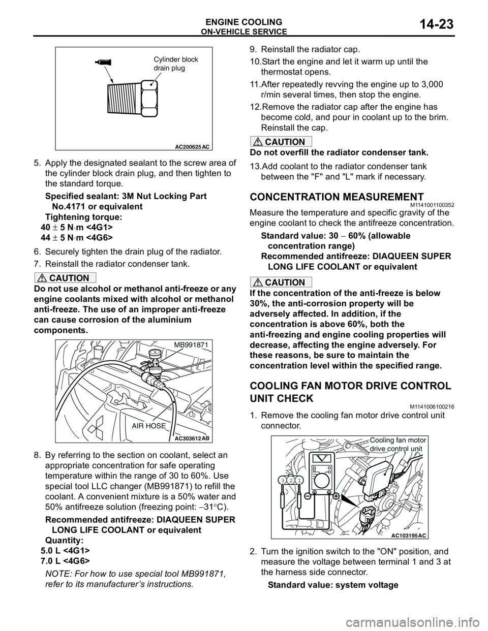
8. By referring to the section on coolant, select an
appropriate concentration for safe operating
temperature within the range of 30 to 60%. Use
special tool LLC changer (MB991871) to refill the
coolant. A convenient mixture is a 50% water and
50% antifreeze solution (freezing point: −31°C).
Recommended antifreeze: DIAQUEEN SUPER
LONG LIFE COOLANT or equivalent
Quantity:
5.0 L <4G1>
7.0 L <4G6>
NOTE: For how to use special tool MB991871,
refer to its manufacturer’s instructions.9. Reinstall the radiator cap.
10.Start the engine and let it warm up until the
thermostat opens.
11.After repeatedly revving the engine up to 3,000
r/min several times, then stop the engine.
12.Remove the radiator cap after the engine has
become cold, and pour in coolant up to the brim.
Reinstall the cap.
CAUTION
Do not overfill the radiator condenser tank.
13.Add coolant to the radiator condenser tank
between the "F" and "L" mark if necessary.
CONCENTRATION MEASUREMENTM1141001100352
Measure the temperature and specific gravity of the
engine coolant to check the antifreeze concentration.
Standard value: 30 − 60% (allowable
concentration range)
Recommended antifreeze: DIAQUEEN SUPER
LONG LIFE COOLANT or equivalent
CAUTION
If the concentration of the anti-freeze is below
30%, the anti-corrosion property will be
adversely affected. In addition, if the
concentration is above 60%, both the
anti-freezing and engine cooling properties will
decrease, affecting the engine adversely. For
these reasons, be sure to maintain the
concentration level within the specified range.
COOLING FAN MOTOR DRIVE CONTROL
UNIT CHECK
M1141006100216
1. Remove the cooling fan motor drive control unit
connector.
2. Turn the ignition switch to the "ON" position, and
measure the voltage between terminal 1 and 3 at
the harness side connector.
Standard value: system voltage
AC200625
Cylinder block
drain plug
AC
AC303612AB
MB991871
AIR HOSE
AC103195
Y1716AU
1 23
AC
Cooling fan motor
drive control unit
Page 65 of 788
16-1
GROUP 16
ENGINE
ELECTRICAL
CONTENTS
CHARGING SYSTEM . . . . . . . .
16-2
GENERAL INFORMATION . . . . . .
16-2
SERVICE SPECIFICATIONS. . . . .16-3
SPECIAL TOOL . . . . . . . . . . . . . . .16-3
ON-VEHICLE SERVICE. . . . . . . . .16-3
ALTERNATOR OUTPUT LINE VOLTAGE
DROP TEST . . . . . . . . . . . . . . . . . . . . . 16-3
OUTPUT CURRENT TEST . . . . . . . . . . 16-5
REGULATED VOLTAGE TEST . . . . . . . 16-7
WAVEFORM CHECK USING AN
OSCILLOSCOPE . . . . . . . . . . . . . . . . . . 16-9
ALTERNATOR ASSEMBLY . . . . .16-12
REMOVAL AND INSTALLATION
<4G1> . . . . . . . . . . . . . . . . . . . . . . . . . . 16-12
REMOVAL AND INSTALLATION
<4G6> . . . . . . . . . . . . . . . . . . . . . . . . . . 16-13
DISASSEMBLY AND REASSEMBLY . . 16-15
INSPECTION . . . . . . . . . . . . . . . . . . . . . 16-17
STARTING SYSTEM . . . . . . . . .16-19
GENERAL INFORMATION . . . . . .
16-19
SERVICE SPECIFICATIONS. . . . .16-20
STARTER MOTOR ASSEMBLY . .16-21
REMOVAL AND INSTALLATION
<4G1> . . . . . . . . . . . . . . . . . . . . . . . . . . 16-21
REMOVAL AND INSTALLATION
<4G6> . . . . . . . . . . . . . . . . . . . . . . . . . . 16-22
STARTER MOTOR ASSEMBLY
INSPECTION . . . . . . . . . . . . . . . . . . . . . 16-23
DISASSEMBLY AND REASSEMBLY . . 16-26
INSPECTION . . . . . . . . . . . . . . . . . . . . . 16-27
IGNITION SYSTEM . . . . . . . . . 16-30
GENERAL INFORMATION . . . . . .
16-30
SERVICE SPECIFICATIONS . . . . .16-31
SPECIAL TOOL . . . . . . . . . . . . . . .16-31
ON-VEHICLE SERVICE . . . . . . . . .16-32
IGNITION COIL (WITH BUILT-IN
POWER TRANSISTOR) CHECK . . . . . . 16-32
RESISTIVE CORD CHECK . . . . . . . . . . 16-32
SPARK PLUG CHECK AND
CLEANING <4G1> . . . . . . . . . . . . . . . . . 16-32
SPARK PLUG CHECK AND
CLEANING <4G6> . . . . . . . . . . . . . . . . . 16-33
CAMSHAFT POSITION SENSOR
CHECK . . . . . . . . . . . . . . . . . . . . . . . . . . 16-33
CRANK ANGLE SENSOR CHECK . . . . 16-33
DETONATION SENSOR CHECK . . . . . 16-33
IGNITION SECONDARY VOLTAGE
WAVEFORM CHECK USING AN
OSCILLOSCOPE . . . . . . . . . . . . . . . . . . 16-33
IGNITION COIL RELAY CHECK . . . . . . 16-37
IGNITION COIL . . . . . . . . . . . . . . . .16-38
REMOVAL AND INSTALLATION
<4G1>. . . . . . . . . . . . . . . . . . . . . . . . . . . 16-38
REMOVAL AND INSTALLATION
<4G6>. . . . . . . . . . . . . . . . . . . . . . . . . . . 16-39
CAMSHAFT POSITION SENSOR .16-40
REMOVAL AND INSTALLATION . . . . . . 16-40
CRANKSHAFT POSITION SENSOR16-41
REMOVAL AND INSTALLATION
<4G1>. . . . . . . . . . . . . . . . . . . . . . . . . . . 16-41
REMOVAL AND INSTALLATION
<4G6>. . . . . . . . . . . . . . . . . . . . . . . . . . . 16-42
DETONATION SENSOR . . . . . . . .16-43
REMOVAL AND INSTALLATION . . . . . . 16-43
Page 66 of 788
CHARGING SYSTEM
ENGINE ELECTRICAL16-2
CHARGING SYSTEM
GENERAL INFORMATIONM1161000100522
The charging system uses the alternator output to
keep the battery charged at a constant level under
various electrical loads.
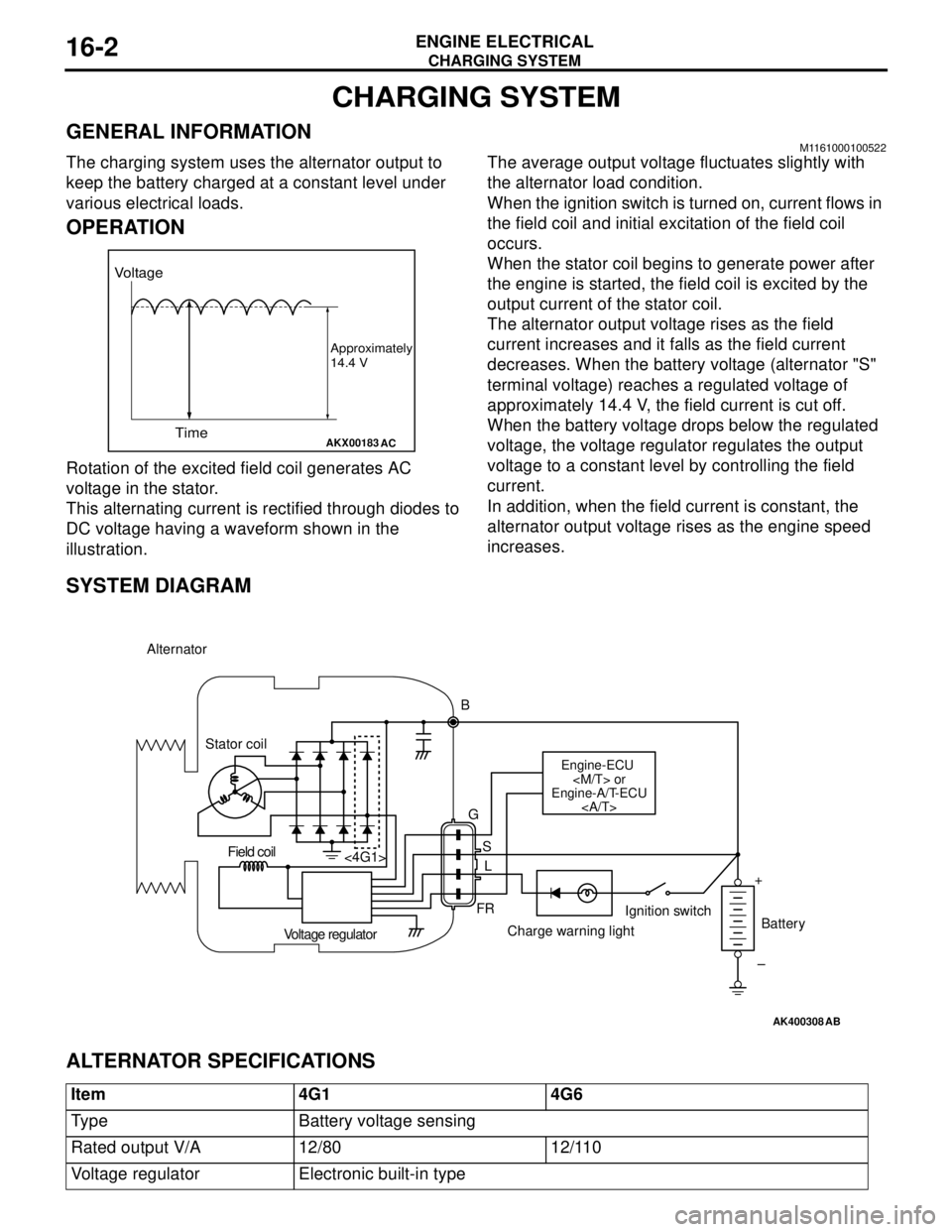
OPERATION
Rotation of the excited field coil generates AC
voltage in the stator.
This alternating current is rectified through diodes to
DC voltage having a waveform shown in the
illustration.The average output voltage fluctuates slightly with
the alternator load condition.
When the ignition switch is turned on, current flows in
the field coil and initial excitation of the field coil
occurs.
When the stator coil begins to generate power after
the engine is started, the field coil is excited by the
output current of the stator coil.
The alternator output voltage rises as the field
current increases and it falls as the field current
decreases. When the battery voltage (alternator "S"
terminal voltage) reaches a regulated voltage of
approximately 14.4 V, the field current is cut off.
When the battery voltage drops below the regulated
voltage, the voltage regulator regulates the output
voltage to a constant level by controlling the field
current.
In addition, when the field current is constant, the
alternator output voltage rises as the engine speed
increases.
SYSTEM DIAGRAM
ALTERNATOR SPECIFICATIONS
AKX00183
Voltage
Time
Approximately
14.4 V
AC
AK400308
Alternator
B
Stator coil
Engine-ECU
Engine-A/T-ECU
G
S
L
FR <4G1>
Voltage regulatorCharge warning lightIgnition switch
Battery Field coil
+
–
AB
Item 4G1 4G6
Type Battery voltage sensing
Rated output V/A 12/80 12/110
Voltage regulator Electronic built-in type
Page 68 of 788
CHARGING SYSTEM
ENGINE ELECTRICAL16-4
2. Turn the ignition switch to the "LOCK" (OFF)
position.
3. Disconnect the negative battery cable.
4. Connect a clamp-type DC test ammeter with a
range of 0 − 120 A to the alternator "B" terminal
output wire.
NOTE: The way of disconnecting the alternator
output wire and of connecting the ammeter is
possibly not found the problem that the output
current is dropping due to the insufficient
connection between terminal "B" and the output
wire.
5. Connect a digital-type voltmeter between the
alternator "B" terminal and the battery (+)
terminal. [Connect the (+) lead of the voltmeter to
the "B" terminal and the connect the (-) lead of the
voltmeter to the battery (+) cable].
6. Reconnect the negative battery cable.
7. Connect a tachometer or the MUT-II/III (Refer to
GROUP 11A − On-vehicle Service − Idle speed
check <4G1> P.11A-11 or GROUP 11C −
On-vehicle Service − Idle speed check <4G6>
P.11C-11).
8. Leave the hood open.
9. Start the engine.
10.With the engine running at 2,500 r/min, turn the
headlamps and other lamps on and off to adjust
the alternator load so that the value displayed on
the ammeter is slightly above 30 A.Adjust the engine speed by gradually decreasing
it until the value displayed on the ammeter is 30
A. Take a reading of the value displayed on the
voltmeter at this time.
Limit: maximum 0.3 V
NOTE: When the alternator output is high and the
value displayed on the ammeter does not
decrease until 30 A, set the value to 40 A. Read
the value displayed on the voltmeter at this time.
When the value range is 40 A, the limit is
maximum 0.4 V.
11.If the value displayed on the voltmeter is above
the limit value, there is probably a malfunction in
the alternator output wire, so check the wiring
between the alternator "B" terminal and the
battery (+) terminal (including fusible link).
If a terminal is not sufficiently tight or if the
harness has become discolored due to
overheating, repair and then test again.
12.After the test, run the engine at idle.
13.Turn off all lamps and the ignition switch.
14.Remove the tachometer or the MUT-II/III.
15.Disconnect the negative battery cable.
16.Disconnect the ammeter and voltmeter.
17.Connect the negative battery cable.