Ring antenna MITSUBISHI LANCER 2005 Workshop Manual
[x] Cancel search | Manufacturer: MITSUBISHI, Model Year: 2005, Model line: LANCER, Model: MITSUBISHI LANCER 2005Pages: 788, PDF Size: 45.98 MB
Page 327 of 788
TA I L G AT E
BODY42-49
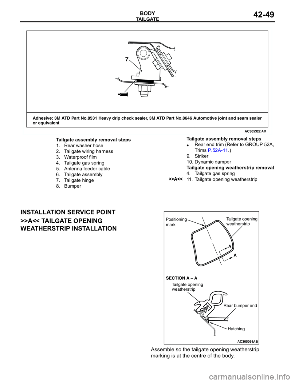
INSTALLATION SERVICE POINT
>>A<< TAILGATE OPENING
WEATHERSTRIP INSTALLATION
Assemble so the tailgate opening weatherstrip
marking is at the centre of the body.
AC305322
Adhesive: 3M ATD Part No.8531 Heavy drip check sealer, 3M ATD Part No.8646 Automotive joint and seam sealer
or equivalent
AB
7
Tailgate assembly removal steps
1. Rear washer hose
2. Tailgate wiring harness
3. Waterproof film
4. Tailgate gas spring
5. Antenna feeder cable
6. Tailgate assembly
7. Tailgate hinge
8. Bumper•Rear end trim (Refer to GROUP 52A,
Trims P.52A-11.)
9. Striker
10. Dynamic damper
Tailgate opening weatherstrip removal
4. Tailgate gas spring
>>A<<11. Tailgate opening weatherstrip Tailgate assembly removal steps
AC305091
Positioning
mark
AB
Tailgate opening
weatherstrip
Rear bumper end
Tailgate opening
weatherstrip SECTION A – AA
A
Hatching
Page 394 of 788
IGNITION SWITCH
CHASSIS ELECTRICAL54A-6
IGNITION SWITCH
GENERAL INFORMATIONM1543009901274
IGNITION KEY REMINDER BUZZER
The ignition key reminder buzzer will sound under
the following condition, and warn the driver to
remove the ignition key.
•The driver's door is opened when the ignition
switch is at "LOCK" (OFF) or "ACC" position
without removing the ignition key.
However, the lamp reminder buzzer will take
precedence over this function.
DOOR LOCK PREVENTION FUNCTION
If the key is left in the ignition switch while the driver’s
door opened or the assistant door opened, all door
are automatically unlock to prevent locking the
ignition key in the vehicle after door is locked.
IMMOBILIZER SYSTEM
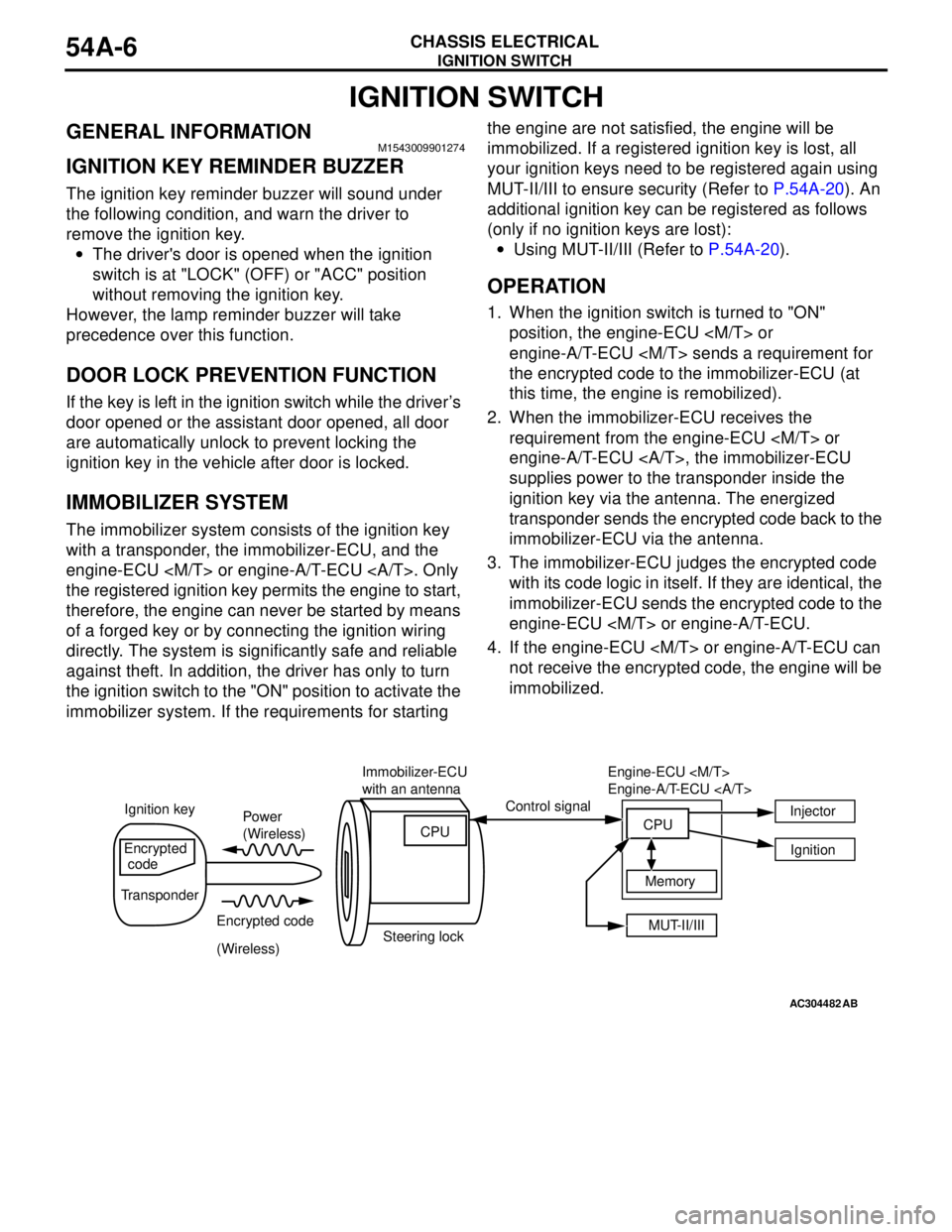
The immobilizer system consists of the ignition key
with a transponder, the immobilizer-ECU, and the
engine-ECU
the registered ignition key permits the engine to start,
therefore, the engine can never be started by means
of a forged key or by connecting the ignition wiring
directly. The system is significantly safe and reliable
against theft. In addition, the driver has only to turn
the ignition switch to the "ON" position to activate the
immobilizer system. If the requirements for starting the engine are not satisfied, the engine will be
immobilized. If a registered ignition key is lost, all
your ignition keys need to be registered again using
MUT-II/III to ensure security (Refer to P.54A-20). An
additional ignition key can be registered as follows
(only if no ignition keys are lost):
•Using MUT-II/III (Refer to P.54A-20).
OPERATION
1. When the ignition switch is turned to "ON"
position, the engine-ECU
engine-A/T-ECU
the encrypted code to the immobilizer-ECU (at
this time, the engine is remobilized).
2. When the immobilizer-ECU receives the
requirement from the engine-ECU
engine-A/T-ECU , the immobilizer-ECU
supplies power to the transponder inside the
ignition key via the antenna. The energized
transponder sends the encrypted code back to the
immobilizer-ECU via the antenna.
3. The immobilizer-ECU judges the encrypted code
with its code logic in itself. If they are identical, the
immobilizer-ECU sends the encrypted code to the
engine-ECU
4. If the engine-ECU
not receive the encrypted code, the engine will be
immobilized.
AC304482AB
Power
(Wireless)
Encrypted code
(Wireless) Ignition keyControl signal
Encrypted
code
TransponderImmobilizer-ECU
with an antenna
Steering lockCPU
MUT-II/III Memory Engine-ECU
Engine-A/T-ECU
CPUInjector
Ignition
Page 398 of 788
IGNITION SWITCH
CHASSIS ELECTRICAL54A-10
DIAGNOSTIC TROUBLE CODE
PROCEDURES
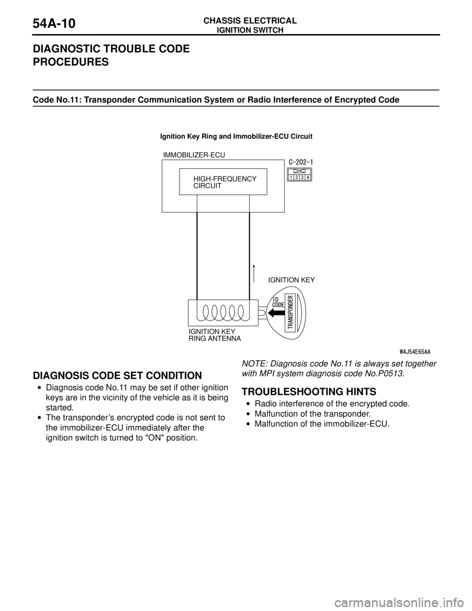
Code No.11: Transponder Communication System or Radio Interference of Encrypted Code
DIAGNOSIS CODE SET CONDITION
•Diagnosis code No.11 may be set if other ignition
keys are in the vicinity of the vehicle as it is being
started.
•The transponder’s encrypted code is not sent to
the immobilizer-ECU immediately after the
ignition switch is turned to "ON" position.NOTE: Diagnosis code No.11 is always set together
with MPI system diagnosis code No.P0513.TROUBLESHOOTING HINTS
•Radio interference of the encrypted code.
•Malfunction of the transponder.
•Malfunction of the immobilizer-ECU.
HIGH-FREQUENCY
CIRCUIT IMMOBILIZER-ECU
IGNITION KEY
IGNITION KEY
RING ANTENNA
Ignition Key Ring and Immobilizer-ECU Circuit
Page 622 of 788
DASH PANEL
CONFIGURATION DIAGRAMS80-16
DASH PANEL
DASH PANEL
NOTE: The connector colour marked by * is for the
female side. For the male side, the colour is grey for
Sedan, and milk white for Wagon.
AC301140
16
C-06
C-05 C-02
C-01
C-34
C-32
C-31
C-29
C-27
C-25C-24C-22
C-21 Connector colour
code
B : Black
BR : Brown
G : Green
GR : Gray
L : Blue
None : Milk white
O : Orange
R : Red
V : Violet
Y : YellowConnector
symbol
-01
thru
-36C
C-04 C-03
C-36
C-33
C-35
6
J/B
AB
5
14
15
C-08
C-09
C-11
C-12 C-10
C-14
C-15
C-13
Instrument panel
wiring harness
Control wiring
harness
C-19
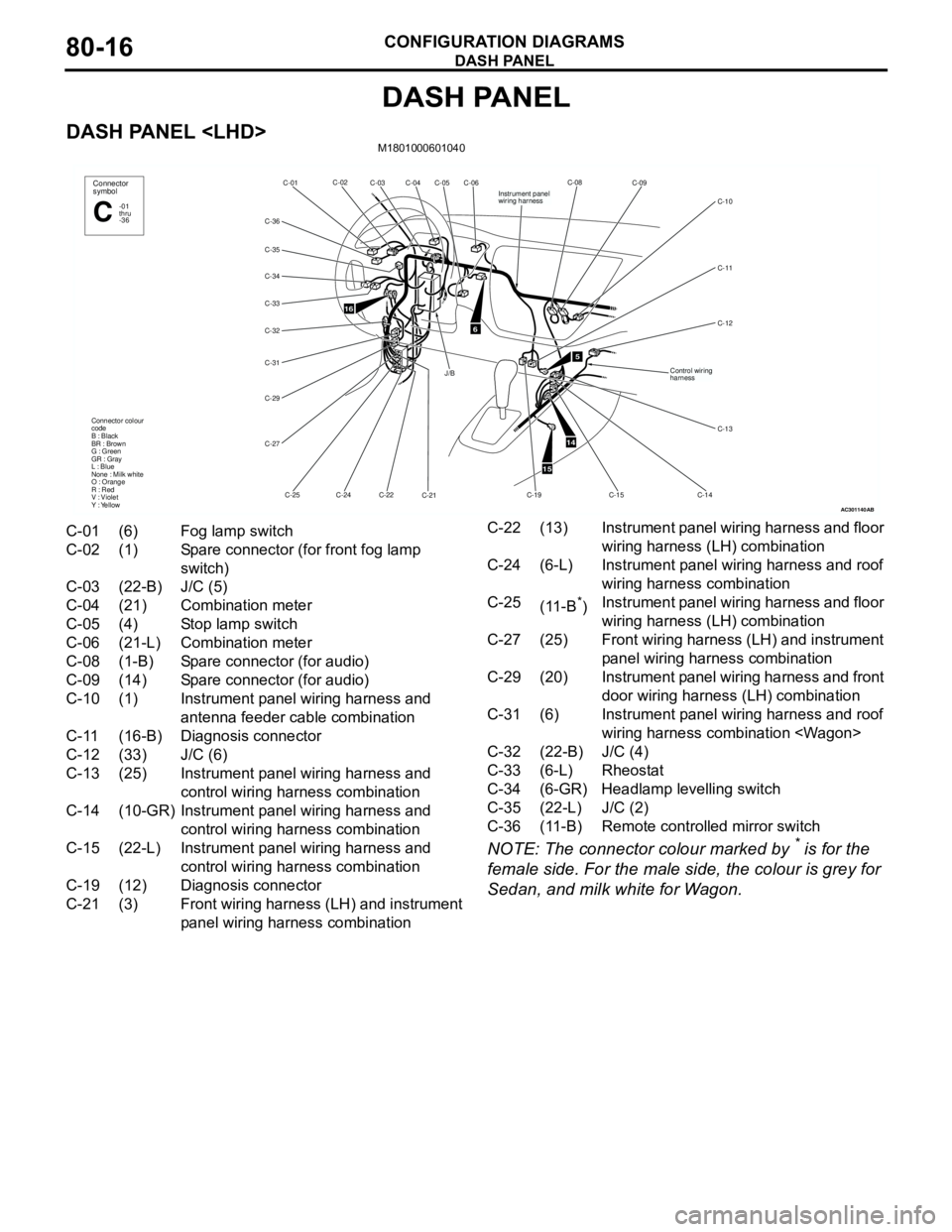
C-01 (6) Fog lamp switch
C-02 (1) Spare connector (for front fog lamp
switch)
C-03 (22-B) J/C (5)
C-04 (21) Combination meter
C-05 (4) Stop lamp switch
C-06 (21-L) Combination meter
C-08 (1-B) Spare connector (for audio)
C-09 (14) Spare connector (for audio)
C-10 (1) Instrument panel wiring harness and
antenna feeder cable combination
C-11 (16-B) Diagnosis connector
C-12 (33) J/C (6)
C-13 (25) Instrument panel wiring harness and
control wiring harness combination
C-14 (10-GR) Instrument panel wiring harness and
control wiring harness combination
C-15 (22-L) Instrument panel wiring harness and
control wiring harness combination
C-19 (12) Diagnosis connector
C-21 (3) Front wiring harness (LH) and instrument
panel wiring harness combinationC-22 (13) Instrument panel wiring harness and floor
wiring harness (LH) combination
C-24 (6-L) Instrument panel wiring harness and roof
wiring harness combination
C-25
(11-B
*)Instrument panel wiring harness and floor
wiring harness (LH) combination
C-27 (25) Front wiring harness (LH) and instrument
panel wiring harness combination
C-29 (20) Instrument panel wiring harness and front
door wiring harness (LH) combination
C-31 (6) Instrument panel wiring harness and roof
wiring harness combination
C-32 (22-B) J/C (4)
C-33 (6-L) Rheostat
C-34 (6-GR) Headlamp levelling switch
C-35 (22-L) J/C (2)
C-36 (11-B) Remote controlled mirror switch
Page 623 of 788
DASH PANEL
CONFIGURATION DIAGRAMS80-17
DASH PANEL
NOTE: The connector colour marked by
* is for the
female side.For the male side, the colour is grey for
Sedan, and milk white for Wagon.
AC301143
C-140C-102C-103 C-101
C-132 C-139
C-130 Y
4
Connector
symbol
-101
thru
-140C
Connector colour
code
B : Black
BR : Brown
G : Green
GR : Gray
L : Blue
None : Milk white
O : Orange
R : Red
V : Violet
Y : Yellow
Instrument panel
wiring harness
C-131
C-133
AB
C-104 C-106 C-107
C-109
C-110
C-112
C-114
C-116
C-119 C-126
C-127 C-128
C-129
2
C-108
C-124
C-125C-122
C-123
3
Control wiring
harness
A/C wiring
harness
Antenna
feeder
cable
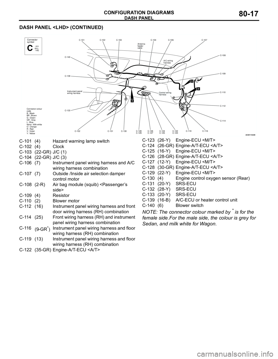
C-101 (4) Hazard warning lamp switch
C-102 (4) Clock
C-103 (22-GR) J/C (1)
C-104 (22-GR) J/C (3)
C-106 (7) Instrument panel wiring harness and A/C
wiring harness combination
C-107 (7) Outside /Inside air selection damper
control motor
C-108 (2-R) Air bag module (squib)
C-109 (4) Resistor
C-110 (2) Blower motor
C-112 (16) Instrument panel wiring harness and front
door wiring harness (RH) combination
C-114 (25) Front wiring harness (RH) and instrument
panel wiring harness combination
C-116
(9-GR
*)Instrument panel wiring harness and floor
wiring harness (RH) combination
C-119 (13) Instrument panel wiring harness and floor
wiring harness (RH) combination
C-122 (35-GR) Engine-A/T-ECU C-123 (26-Y) Engine-ECU
C-124 (26-GR) Engine-A/T-ECU
C-125 (16-Y) Engine-ECU
C-126 (28-GR) Engine-A/T-ECU
C-127 (12-Y) Engine-ECU
C-128 (30-GR) Engine-A/T-ECU
C-129 (22-Y) Engine-ECU
C-130 (4) Engine control oxygen sensor (Rear)
C-131 (20-Y) SRS-ECU
C-132 (28-Y) SRS-ECU
C-133 (20-Y) SRS-ECU
C-139 (16-B) A/C-ECU or heater control unit
C-140 (6) Blower switch
Page 625 of 788
DASH PANEL
CONFIGURATION DIAGRAMS80-19
DASH PANEL
AC301149
C-10C-09 C-08
Control wiring
harness
C-37
C-16
C-17 C-18 C-11
C-19 Y
4
Connector
symbol
-01
thru
-37C
Connector colour
code
B : Black
BR : Brown
G : Green
GR : Gray
L : Blue
None : Milk white
O : Orange
R : Red
V : Violet
Y : Yellow
Instrument panel
wiring harness
AB
C-04 C-07 C-06 C-05 C-02 C-01
J/BC-34
C-33
C-31
C-30
C-28
C-26
C-23
C-24 C-20C-32
C-35
2
C-36
6
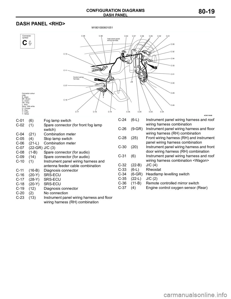
C-01 (6) Fog lamp switch
C-02 (1) Spare connector (for front fog lamp
switch)
C-04 (21) Combination meter
C-05 (4) Stop lamp switch
C-06 (21-L) Combination meter
C-07 (22-GR) J/C (3)
C-08 (1-B) Spare connector (for audio)
C-09 (14) Spare connector (for audio)
C-10 (1) Instrument panel wiring harness and
antenna feeder cable combination
C-11 (16-B) Diagnosis connector
C-16 (20-Y) SRS-ECU
C-17 (28-Y) SRS-ECU
C-18 (20-Y) SRS-ECU
C-19 (12) Diagnosis connector
C-20 (2) No connection
C-23 (13) Instrument panel wiring harness and floor
wiring harness (RH) combinationC-24 (6-L) Instrument panel wiring harness and roof
wiring harness combination
C-26 (9-GR) Instrument panel wiring harness and floor
wiring harness (RH) combination
C-28 (25) Front wiring harness (RH) and instrument
panel wiring harness combination
C-30 (20) Instrument panel wiring harness and front
door wiring harness (RH) combination
C-31 (6) Instrument panel wiring harness and roof
wiring harness combination
C-32 (22-B) J/C (4)
C-33 (6-L) Rheostat
C-34 (6-GR) Headlamp levelling switch
C-35 (22-L) J/C (2)
C-36 (11-B) Remote controlled mirror switch
C-37 (4) Engine control oxygen sensor (Rear)
Page 626 of 788
DASH PANEL
CONFIGURATION DIAGRAMS80-20
DASH PANEL
NOTE: The connector colour marked by
* is for the
female side.For the male side, the colour is grey.
AC301146
Y
16
C-105 C-106 C-107 C-108
A/C wiring
harness
C-109
C-110
C-111
C-113
C-115
C-117
Instrument panel
wiring harness
Control wiring
harness
C-118C-120
C-121
C-128
C-129C-126
C-127C-124
C-125C-122
C-123 Connector colour
code
B : Black
BR : Brown
G : Green
GR : Gray
L : Blue
None : Milk white
O : Orange
R : Red
V : Violet
Y : Yellow
3
Connector
symbol
-101
thru
-140C
Antenna
feeder
cable
AB
5
1415
C-103
C-102
C-101
C-139
C-138
C-137 C-140
C-136 C-135
C-134
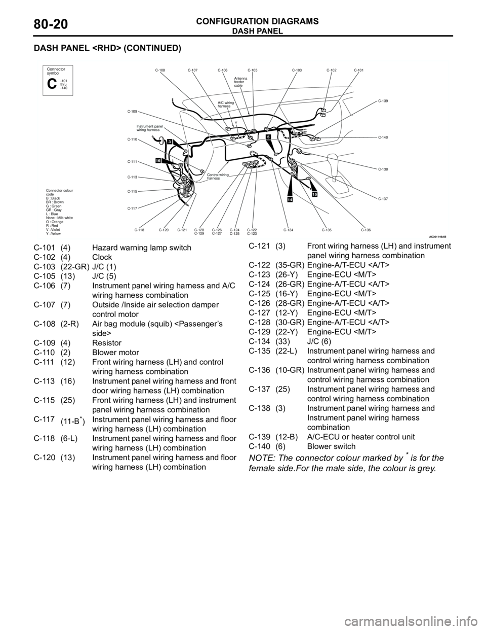
C-101 (4) Hazard warning lamp switch
C-102 (4) Clock
C-103 (22-GR) J/C (1)
C-105 (13) J/C (5)
C-106 (7) Instrument panel wiring harness and A/C
wiring harness combination
C-107 (7) Outside /Inside air selection damper
control motor
C-108 (2-R) Air bag module (squib)
C-109 (4) Resistor
C-110 (2) Blower motor
C-111 (12) Front wiring harness (LH) and control
wiring harness combination
C-113 (16) Instrument panel wiring harness and front
door wiring harness (LH) combination
C-115 (25) Front wiring harness (LH) and instrument
panel wiring harness combination
C-117
(11-B
*)Instrument panel wiring harness and floor
wiring harness (LH) combination
C-118 (6-L) Instrument panel wiring harness and floor
wiring harness (LH) combination
C-120 (13) Instrument panel wiring harness and floor
wiring harness (LH) combinationC-121 (3) Front wiring harness (LH) and instrument
panel wiring harness combination
C-122 (35-GR) Engine-A/T-ECU
C-123 (26-Y) Engine-ECU
C-124 (26-GR) Engine-A/T-ECU
C-125 (16-Y) Engine-ECU
C-126 (28-GR) Engine-A/T-ECU
C-127 (12-Y) Engine-ECU
C-128 (30-GR) Engine-A/T-ECU
C-129 (22-Y) Engine-ECU
C-134 (33) J/C (6)
C-135 (22-L) Instrument panel wiring harness and
control wiring harness combination
C-136 (10-GR) Instrument panel wiring harness and
control wiring harness combination
C-137 (25) Instrument panel wiring harness and
control wiring harness combination
C-138 (3) Instrument panel wiring harness and
Instrument panel wiring harness
combination
C-139 (12-B) A/C-ECU or heater control unit
C-140 (6) Blower switch
Page 628 of 788
FLOOR AND ROOF
CONFIGURATION DIAGRAMS80-22
FLOOR AND ROOF
FLOOR AND ROOF
AC301155
D-06
D-07
D-05 D-04 D-03 D-02 D-01
D-35
D-34
D-33
D-32
D-31
D-30
D-29
D-25
D-28D-27 D-24
D-23 Y
Y
YFloor wiring
harness (LH) Floor wiring
harness (RH)
Instrument panel
wiring harnessConnector
symbol
D
D-26
Roof wiring
harness
Connector colour
code
B : Black
BR : Brown
G : Green
GR : Gray
L : Blue
None : Milk white
O : Orange
R : Red
V : Violet
Y : Yellow
Antenna
feeder cable
D-08
D-13
D-14
D-15
D-16
D-17
D-18
D-19 D-20
D-21 D-22Y
YFuel wiring
harness
7
17
Y
Y
AC
Y
Y D-04 D-36 D-06 D-37
Roof wiring
harness
Antenna
feeder cable
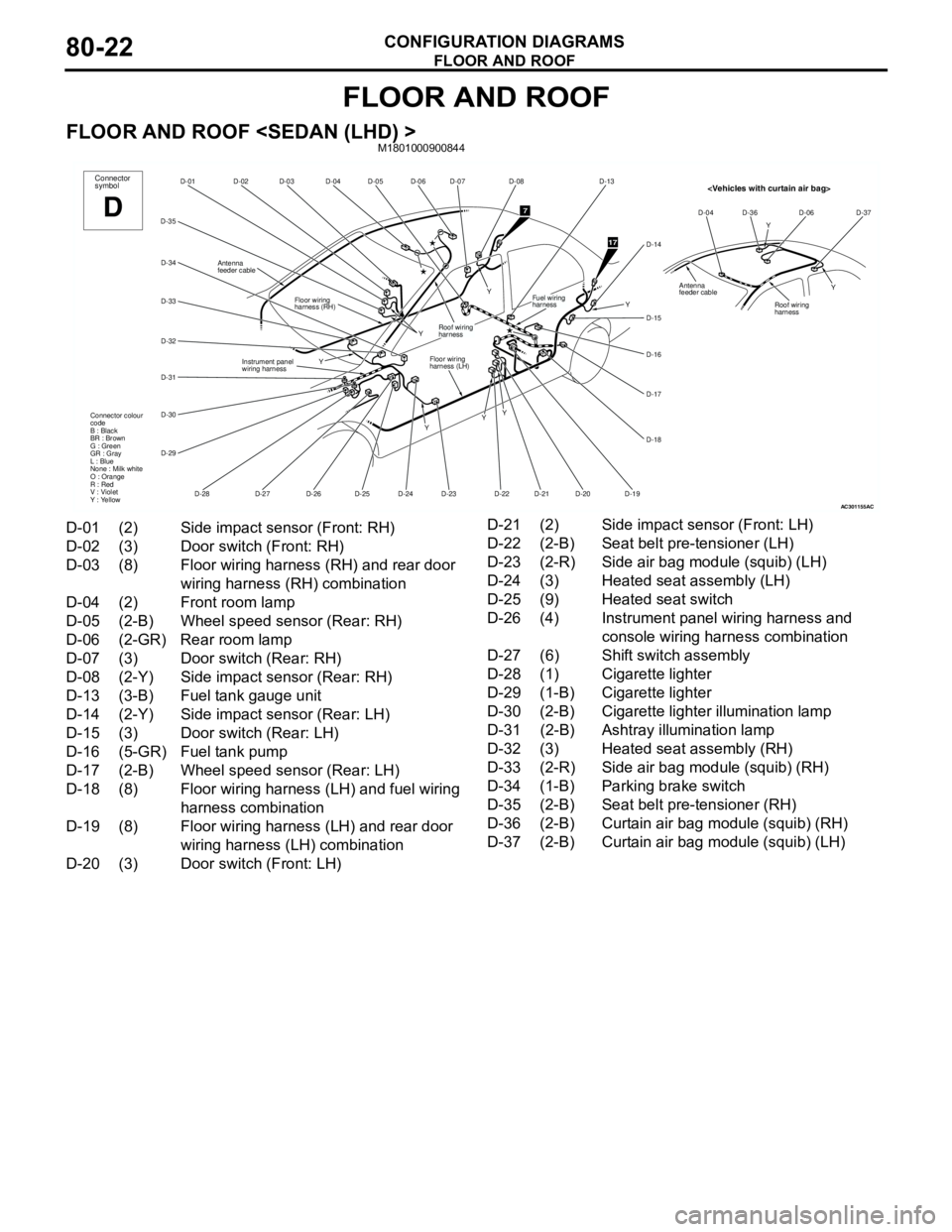
D-01 (2) Side impact sensor (Front: RH)
D-02 (3) Door switch (Front: RH)
D-03 (8) Floor wiring harness (RH) and rear door
wiring harness (RH) combination
D-04 (2) Front room lamp
D-05 (2-B) Wheel speed sensor (Rear: RH)
D-06 (2-GR) Rear room lamp
D-07 (3) Door switch (Rear: RH)
D-08 (2-Y) Side impact sensor (Rear: RH)
D-13 (3-B) Fuel tank gauge unit
D-14 (2-Y) Side impact sensor (Rear: LH)
D-15 (3) Door switch (Rear: LH)
D-16 (5-GR) Fuel tank pump
D-17 (2-B) Wheel speed sensor (Rear: LH)
D-18 (8) Floor wiring harness (LH) and fuel wiring
harness combination
D-19 (8) Floor wiring harness (LH) and rear door
wiring harness (LH) combination
D-20 (3) Door switch (Front: LH)D-21 (2) Side impact sensor (Front: LH)
D-22 (2-B) Seat belt pre-tensioner (LH)
D-23 (2-R) Side air bag module (squib) (LH)
D-24 (3) Heated seat assembly (LH)
D-25 (9) Heated seat switch
D-26 (4) Instrument panel wiring harness and
console wiring harness combination
D-27 (6) Shift switch assembly
D-28 (1) Cigarette lighter
D-29 (1-B) Cigarette lighter
D-30 (2-B) Cigarette lighter illumination lamp
D-31 (2-B) Ashtray illumination lamp
D-32 (3) Heated seat assembly (RH)
D-33 (2-R) Side air bag module (squib) (RH)
D-34 (1-B) Parking brake switch
D-35 (2-B) Seat belt pre-tensioner (RH)
D-36 (2-B) Curtain air bag module (squib) (RH)
D-37 (2-B) Curtain air bag module (squib) (LH)
Page 629 of 788
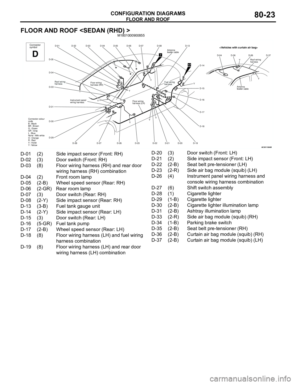
FLOOR AND ROOF
CONFIGURATION DIAGRAMS80-23
FLOOR AND ROOF
AC301158
D-06
D-07
D-05 D-04 D-03 D-02 D-01
D-35
D-34
D-33
D-31
D-30
D-29
D-28D-27
D-23 Y
Y
YFloor wiring
harness (LH) Floor wiring
harness (RH)
Instrument panel
wiring harnessConnector
symbol
D
D-26
Roof wiring
harness
Connector colour
code
B : Black
BR : Brown
G : Green
GR : Gray
L : Blue
None : Milk white
O : Orange
R : Red
V : Violet
Y : Yellow
D-08
D-13
D-14
D-15
D-16
D-17
D-18
D-19 D-20
D-21 D-22Y
YFuel wiring
harness
7
17
Y
Y
Antenna
feeder cable
AB
Y
Y D-04 D-36 D-06 D-37Roof wiring
harness
Antenna
feeder cable
D-01 (2) Side impact sensor (Front: RH)
D-02 (3) Door switch (Front: RH)
D-03 (8) Floor wiring harness (RH) and rear door
wiring harness (RH) combination
D-04 (2) Front room lamp
D-05 (2-B) Wheel speed sensor (Rear: RH)
D-06 (2-GR) Rear room lamp
D-07 (3) Door switch (Rear: RH)
D-08 (2-Y) Side impact sensor (Rear: RH)
D-13 (3-B) Fuel tank gauge unit
D-14 (2-Y) Side impact sensor (Rear: LH)
D-15 (3) Door switch (Rear: LH)
D-16 (5-GR) Fuel tank pump
D-17 (2-B) Wheel speed sensor (Rear: LH)
D-18 (8) Floor wiring harness (LH) and fuel wiring
harness combination
D-19 (8) Floor wiring harness (LH) and rear door
wiring harness (LH) combinationD-20 (3) Door switch (Front: LH)
D-21 (2) Side impact sensor (Front: LH)
D-22 (2-B) Seat belt pre-tensioner (LH)
D-23 (2-R) Side air bag module (squib) (LH)
D-26 (4) Instrument panel wiring harness and
console wiring harness combination
D-27 (6) Shift switch assembly
D-28 (1) Cigarette lighter
D-29 (1-B) Cigarette lighter
D-30 (2-B) Cigarette lighter illumination lamp
D-31 (2-B) Ashtray illumination lamp
D-33 (2-R) Side air bag module (squib) (RH)
D-34 (1-B) Parking brake switch
D-35 (2-B) Seat belt pre-tensioner (RH)
D-36 (2-B) Curtain air bag module (squib) (RH)
D-37 (2-B) Curtain air bag module (squib) (LH)
Page 630 of 788
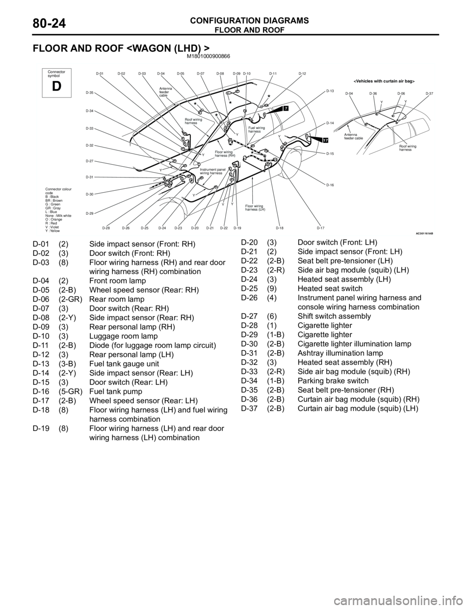
FLOOR AND ROOF
CONFIGURATION DIAGRAMS80-24
FLOOR AND ROOF
AC301161
D-07
D-08 D-05
D-04 D-03 D-02
D-01
D-35
D-34
D-33
D-31
D-30
D-29
D-28
D-24D-19 Y
Y
YConnector
symbol
D
D-20
Roof wiring
harness
Connector colour
code
B : Black
BR : Brown
G : Green
GR : Gray
L : Blue
None : Milk white
O : Orange
R : Red
V : Violet
Y : Yellow
D-09
D-22D-21D-23D-25D-26
D-32
D-27
Y
YInstrument panel
wiring harness
Floor wiring
harness (RH)
Y
Antenna
feeder
cable
D-10
D-12
D-14
D-15
D-16
D-17 D-18
Fuel wiring
harness
7
17Y
D-11
D-13
Floor wiring
harness (LH)
AB
YY D-04 D-36 D-06 D-37
Roof wiring
harness
Antenna
feeder cable
D-01 (2) Side impact sensor (Front: RH)
D-02 (3) Door switch (Front: RH)
D-03 (8) Floor wiring harness (RH) and rear door
wiring harness (RH) combination
D-04 (2) Front room lamp
D-05 (2-B) Wheel speed sensor (Rear: RH)
D-06 (2-GR) Rear room lamp
D-07 (3) Door switch (Rear: RH)
D-08 (2-Y) Side impact sensor (Rear: RH)
D-09 (3) Rear personal lamp (RH)
D-10 (3) Luggage room lamp
D-11 (2-B) Diode (for luggage room lamp circuit)
D-12 (3) Rear personal lamp (LH)
D-13 (3-B) Fuel tank gauge unit
D-14 (2-Y) Side impact sensor (Rear: LH)
D-15 (3) Door switch (Rear: LH)
D-16 (5-GR) Fuel tank pump
D-17 (2-B) Wheel speed sensor (Rear: LH)
D-18 (8) Floor wiring harness (LH) and fuel wiring
harness combination
D-19 (8) Floor wiring harness (LH) and rear door
wiring harness (LH) combinationD-20 (3) Door switch (Front: LH)
D-21 (2) Side impact sensor (Front: LH)
D-22 (2-B) Seat belt pre-tensioner (LH)
D-23 (2-R) Side air bag module (squib) (LH)
D-24 (3) Heated seat assembly (LH)
D-25 (9) Heated seat switch
D-26 (4) Instrument panel wiring harness and
console wiring harness combination
D-27 (6) Shift switch assembly
D-28 (1) Cigarette lighter
D-29 (1-B) Cigarette lighter
D-30 (2-B) Cigarette lighter illumination lamp
D-31 (2-B) Ashtray illumination lamp
D-32 (3) Heated seat assembly (RH)
D-33 (2-R) Side air bag module (squib) (RH)
D-34 (1-B) Parking brake switch
D-35 (2-B) Seat belt pre-tensioner (RH)
D-36 (2-B) Curtain air bag module (squib) (RH)
D-37 (2-B) Curtain air bag module (squib) (LH)