door lock MITSUBISHI LANCER 2005 Workshop Manual
[x] Cancel search | Manufacturer: MITSUBISHI, Model Year: 2005, Model line: LANCER, Model: MITSUBISHI LANCER 2005Pages: 788, PDF Size: 45.98 MB
Page 280 of 788

42-2
TROUBLESHOOTING . . . . . . . . . .42-26
ON-VEHICLE SERVICE. . . . . . . . .42-27
DOOR FIT ADJUSTMENT. . . . . . . . . . . 42-27
DOOR WINDOW GLASS ADJUSTMENT42-28
GLASS SLIDING MECHANISM CHECK
AND ADJUSTMENT . . . . . . . . . . . . . . . 42-28
POWER WINDOW OPERATING
CURRENT CHECK . . . . . . . . . . . . . . . . 42-28
POWER WINDOW RELAY CHECK . . . 42-29
CIRCUIT BREAKER (INCORPORATED
IN THE POWER WINDOW MOTOR)
INSPECTION . . . . . . . . . . . . . . . . . . . . . 42-29
POWER WINDOW CHECK . . . . . . . . . . 42-29
CENTRAL DOOR LOCKING SYSTEM
INSPECTION . . . . . . . . . . . . . . . . . . . . . 42-29
DOOR OUTSIDE HANDLE PLAY
CHECK . . . . . . . . . . . . . . . . . . . . . . . . . 42-29
DOOR INSIDE HANDLE PLAY
ADJUSTMENT . . . . . . . . . . . . . . . . . . . . 42-30
DOOR ASSEMBLY . . . . . . . . . . . .42-31
REMOVAL AND INSTALLATION . . . . . 42-31
INSPECTION . . . . . . . . . . . . . . . . . . . . . 42-32
DOOR GLASS AND
REGULATOR . . . . . . . . . . . . . . . . .
42-32
REMOVAL AND INSTALLATION . . . . . 42-32
INSPECTION . . . . . . . . . . . . . . . . . . . . . 42-34
DOOR HANDLE AND LATCH . . . .42-36
REMOVAL AND INSTALLATION . . . . . 42-36
INSPECTION . . . . . . . . . . . . . . . . . . . . . 42-37
WINDOW GLASS RUNCHANNEL AND
DOOR OPENING
WEATHERSTRIP . . . . . . . . . . . . . .
42-39
REMOVAL AND INSTALLATION . . . . . 42-39
TRUNK LID . . . . . . . . . . . . . . . .42-41
SPECIAL TOOL . . . . . . . . . . . . . . .
42-41
ON-VEHICLE SERVICE. . . . . . . . .42-41
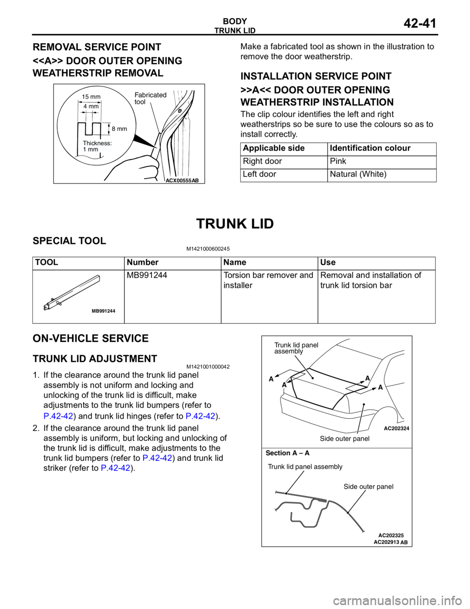
TRUNK LID ADJUSTMENT . . . . . . . . . . 42-41
ADJUSTMENT OF CLEARANCE
AROUND TRUNK LID . . . . . . . . . . . . . . 42-42
TRUNK LID STRIKER ADJUSTMENT . 42-42
TRUNK LID HEIGHT ADJUSTMENT . . 42-42
TRUNK LID . . . . . . . . . . . . . . . . . . .42-43
REMOVAL AND INSTALLATION . . . . . . 42-43
INSPECTION . . . . . . . . . . . . . . . . . . . . . 42-45
TAILGATE . . . . . . . . . . . . . . . . 42-46
SERVICE SPECIFICATIONS . . . . .
42-46
SEALANTS . . . . . . . . . . . . . . . . . . .42-46
SPECIAL TOOL . . . . . . . . . . . . . . .42-46
TROUBLESHOOTING . . . . . . . . . .42-46
ON-VEHICLE SERVICE . . . . . . . . .42-46
TAILGATE FIT ADJUSTMENT. . . . . . . . 42-46
TAILGATE HANDLE PLAY CHECK . . . . 42-47
TAILGATE . . . . . . . . . . . . . . . . . . .42-48
REMOVAL AND INSTALLATION . . . . . . 42-48
TAILGATE HANDLE AND
LATCH . . . . . . . . . . . . . . . . . . . . . .
42-50
REMOVAL AND INSTALLATION . . . . . . 42-50
INSPECTION . . . . . . . . . . . . . . . . . . . . . 42-51
KEYLESS ENTRY SYSTEM . . 42-51
SERVICE SPECIFICATIONS . . . . .
42-51
SPECIAL TOOLS . . . . . . . . . . . . . .42-52
TROUBLESHOOTING . . . . . . . . . .42-53
ON-VEHICLE SERVICE . . . . . . . . .42-53
KEYLESS ENTRY SYSTEM CHECK. . . 42-53
KEYLESS ENTRY SYSTEM TIMER
LOCK FUNCTION INSPECTION . . . . . . 42-53
ENABLING/DISABLING
THE ANSWERBACK FUNCTION . . . . . 42-53
HOW TO REGISTER SECRET CODE . 42-55
TRANSMITTER. . . . . . . . . . . . . . . .42-58
DISASSEMBLY AND REASSEMBLY . . 42-58
INSPECTION . . . . . . . . . . . . . . . . . . . . . 42-59
Page 305 of 788
DOOR
BODY42-27
ON-VEHICLE SERVICE
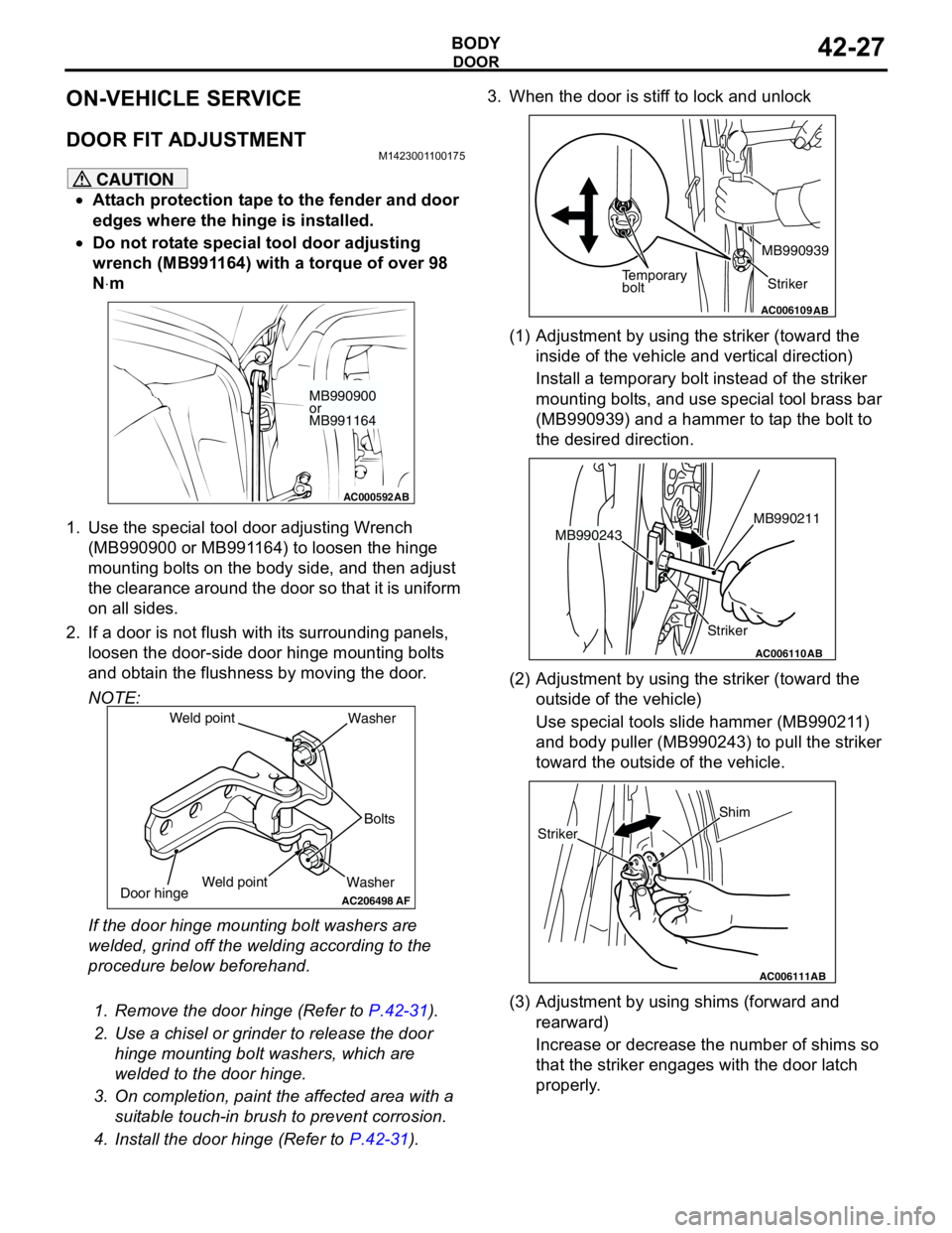
DOOR FIT ADJUSTMENTM1423001100175
CAUTION
•Attach protection tape to the fender and door
edges where the hinge is installed.
•Do not rotate special tool door adjusting
wrench (MB991164) with a torque of over 98
N⋅m
1. Use the special tool door adjusting Wrench
(MB990900 or MB991164) to loosen the hinge
mounting bolts on the body side, and then adjust
the clearance around the door so that it is uniform
on all sides.
2. If a door is not flush with its surrounding panels,
loosen the door-side door hinge mounting bolts
and obtain the flushness by moving the door.
NOTE:
If the door hinge mounting bolt washers are
welded, grind off the welding according to the
procedure below beforehand.
.
1. Remove the door hinge (Refer to P.42-31).
2. Use a chisel or grinder to release the door
hinge mounting bolt washers, which are
welded to the door hinge.
3. On completion, paint the affected area with a
suitable touch-in brush to prevent corrosion.
4. Install the door hinge (Refer to P.42-31).3. When the door is stiff to lock and unlock
(1) Adjustment by using the striker (toward the
inside of the vehicle and vertical direction)
Install a temporary bolt instead of the striker
mounting bolts, and use special tool brass bar
(MB990939) and a hammer to tap the bolt to
the desired direction.
(2) Adjustment by using the striker (toward the
outside of the vehicle)
Use special tools slide hammer (MB990211)
and body puller (MB990243) to pull the striker
toward the outside of the vehicle.
(3) Adjustment by using shims (forward and
rearward)
Increase or decrease the number of shims so
that the striker engages with the door latch
properly.
AC000592
MB990900
or
MB991164
AB
AC206498
WasherBolts Washer
Door hinge
AF
Weld point Weld point
AC006109AB
Temporary
boltStriker MB990939
AC006110
StrikerMB990211
MB990243
AB
AC006111AB
Shim
Striker
Page 307 of 788
DOOR
BODY42-29
3. If the operation current is outside the standard
value, refer to GROUP 54B, Troubleshooting
P.54B-17, refer to GROUP 54C, Troubleshooting
P.54C-4.
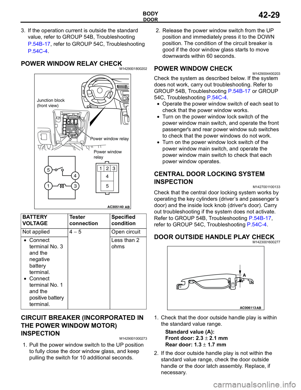
POWER WINDOW RELAY CHECKM1429001800202
CIRCUIT BREAKER (INCORPORATED IN
THE POWER WINDOW MOTOR)
INSPECTION
M1429001000273
1. Pull the power window switch to the UP position
to fully close the door window glass, and keep
pulling the switch for 10 additional seconds.2. Release the power window switch from the UP
position and immediately press it to the DOWN
position. The condition of the circuit breaker is
good if the door window glass starts to move
downwards within 60 seconds.
POWER WINDOW CHECKM1429004400203
Check the system as described below. If the system
does not work, carry out troubleshooting. Refer to
GROUP 54B, Troubleshooting P.54B-17 or GROUP
54C, Troubleshooting P.54C-4.
•Operate the power window switch of each seat to
check that the power window works.
•Turn on the power window lock switch of the
power window main switch, and operate the front
passenger's and rear power window sub switches
to check that the power windows do not work.
•Turn on the power window lock switch of the
power window main switch, and operate the
power window main switch to check that each
power window operates.
CENTRAL DOOR LOCKING SYSTEM
INSPECTION
M1427001100133
Check that the central door locking system works by
operating the key cylinders (driver’s and passenger’s
door) and the inside lock knob (driver's door). Carry
out troubleshooting if the system does not activate.
Refer to GROUP 54B, Troubleshooting P.54B-17,
refer to GROUP 54C, Troubleshooting P.54C-4.
DOOR OUTSIDE HANDLE PLAY CHECKM1423001600277
1. Check that the door outside handle play is within
the standard value range.
Standard value (A):
Front door: 2.3 ± 2.1 mm
Rear door: 1.3 ± 1.7 mm
2. If the door outside handle play is not within the
standard value range, check the door outside
handle or the door latch assembly. Replace, if
necessary. BATTERY
VOLTAGETester
connectionSpecified
condition
Not applied 4 − 5 Open circuit
•Connect
terminal No. 3
and the
negative
battery
terminal.
•Connect
terminal No. 1
and the
positive battery
terminal.Less than 2
ohms
AC305140
123
4
5
1
3 4 5
AB
Junction block
(front view)
Power window relay
Power window
relay
AC006113
AB
A
Page 308 of 788
DOOR
BODY42-30
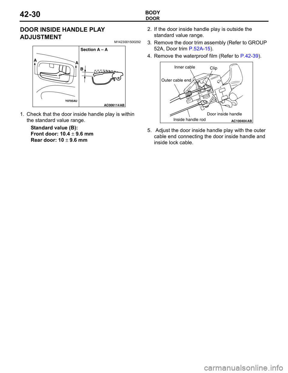
DOOR INSIDE HANDLE PLAY
ADJUSTMENT
M1423001500292
1. Check that the door inside handle play is within
the standard value range.
Standard value (B):
Front door: 10.4 ± 9.6 mm
Rear door: 10 ± 9.6 mm2. If the door inside handle play is outside the
standard value range.
3. Remove the door trim assembly (Refer to GROUP
52A, Door trim P.52A-15).
4. Remove the waterproof film (Refer to P.42-39).
5. Adjust the door inside handle play with the outer
cable end connecting the door inside handle and
inside lock cable.
AC006114Y0705AUAB
A
A
BSection A – A
AC100404
AB
Clip Inner cable
Outer cable end
Inside handle rodDoor inside handle
Page 314 of 788
DOOR
BODY42-36
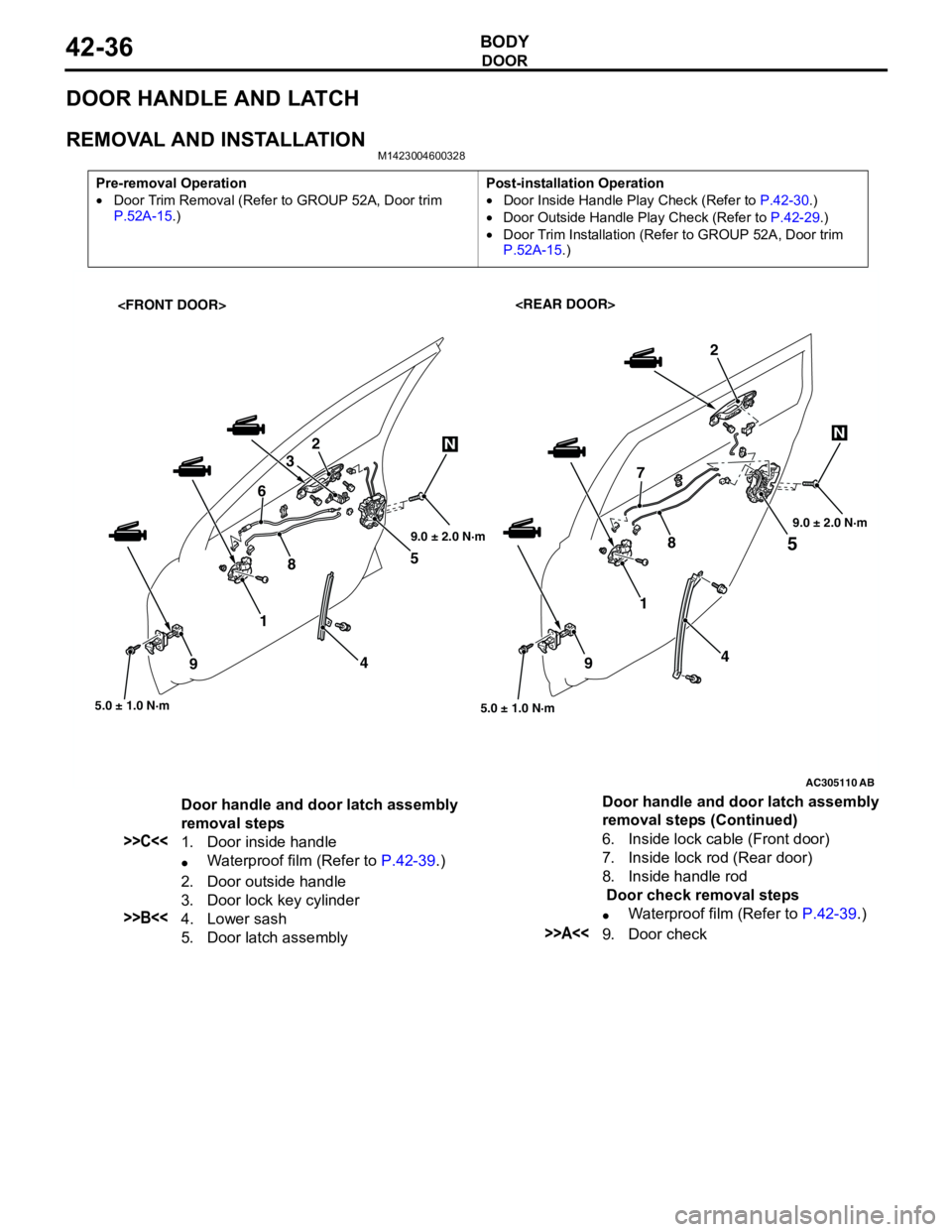
DOOR HANDLE AND LATCH
REMOVAL AND INSTALLATIONM1423004600328
Pre-removal Operation
•Door Trim Removal (Refer to GROUP 52A, Door trim
P.52A-15.)Post-installation Operation
•Door Inside Handle Play Check (Refer to P.42-30.)
•Door Outside Handle Play Check (Refer to P.42-29.)
•Door Trim Installation (Refer to GROUP 52A, Door trim
P.52A-15.)
AC305110
5
5.0 ± 1.0 N·m
1
4
9
2
AB
45 2
3
87
5.0 ± 1.0 N·m
1 6
9
NN
89.0 ± 2.0 N·m9.0 ± 2.0 N·m
Door handle and door latch assembly
removal steps
>>C<<1. Door inside handle
•Waterproof film (Refer to P.42-39.)
2. Door outside handle
3. Door lock key cylinder
>>B<<4. Lower sash
5. Door latch assembly6. Inside lock cable (Front door)
7. Inside lock rod (Rear door)
8. Inside handle rod
Door check removal steps
•Waterproof film (Refer to P.42-39.)>>A<<9. Door check Door handle and door latch assembly
removal steps (Continued)
Page 315 of 788
DOOR
BODY42-37
INSTALLATION SERVICE POINTS
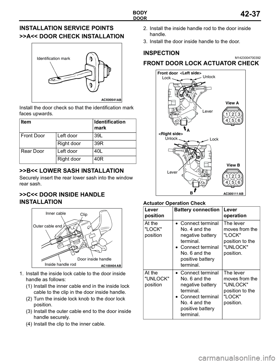
>>A<< DOOR CHECK INSTALLATION
Install the door check so that the identification mark
faces upwards.
>>B<< LOWER SASH INSTALLATION
Securely insert the rear lower sash into the window
rear sash.
>>C<< DOOR INSIDE HANDLE
INSTALLATION
1. Install the inside lock cable to the door inside
handle as follows:
(1) Install the inner cable end in the inside lock
cable to the clip in the door inside handle.
(2) Turn the inside lock knob to the door lock
position.
(3) Install the outer cable end to the door inside
handle securely.
(4) Install the clip to the inner cable.2. Install the inside handle rod to the door inside
handle.
3. Install the door inside handle to the door.
INSPECTIONM1423004700392
FRONT DOOR LOCK ACTUATOR CHECK
Actuator Operation Check Item Identification
mark
Front Door Left door 39L
Right door 39R
Rear Door Left door 40L
Right door 40R
ACX00541
Identification mark
AB
AC100404
AB
Clip Inner cable
Outer cable end
Inside handle rodDoor inside handleLever
positionBattery connection Lever
operation
At the
"LOCK"
position•Connect terminal
No. 4 and the
negative battery
terminal.
•Connect terminal
No. 6 and the
positive battery
terminal.The lever
moves from the
"LOCK"
position to the
"UNLOCK"
position.
At the
"UNLOCK"
position•Connect terminal
No. 6 and the
negative battery
terminal.
•Connect terminal
No. 4 and the
positive battery
terminal.The lever
moves from the
"UNLOCK"
position to the
"LOCK"
position.
42
53
6 1
42
53
6 1
AC305111B
A
AB
LockUnlock
View A
View B Unlock
Lock Front door
Lever
Page 316 of 788
DOOR
BODY42-38
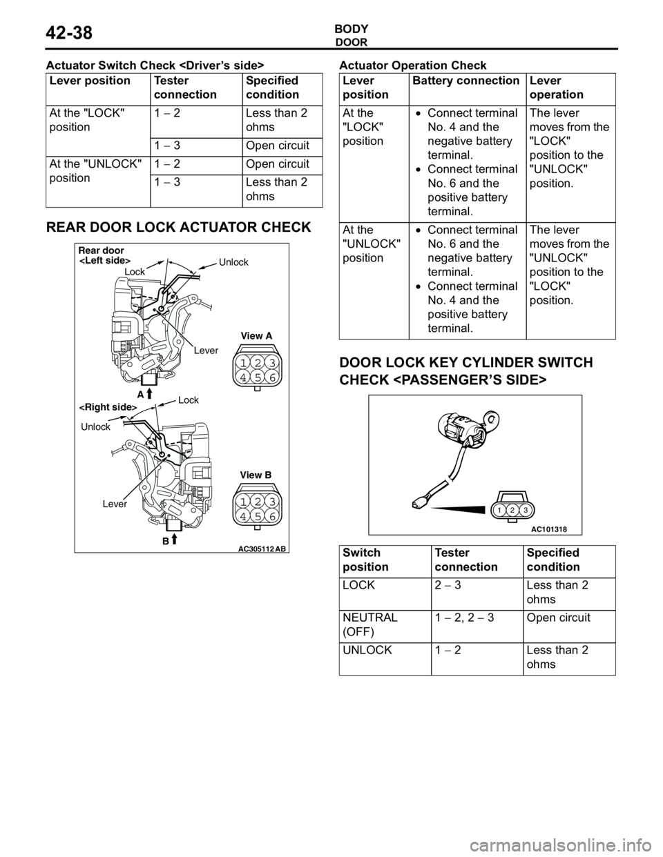
Actuator Switch Check
REAR DOOR LOCK ACTUATOR CHECK
Actuator Operation Check
DOOR LOCK KEY CYLINDER SWITCH
CHECK
Lever position Tester
connectionSpecified
condition
At the "LOCK"
position1 − 2 Less than 2
ohms
1 − 3 Open circuit
At the "UNLOCK"
position1 − 2 Open circuit
1 − 3 Less than 2
ohms
23
41
56
23
41
56
AC305112B
A
AB
Rear door
LockUnlock
View A
View B UnlockLock
Lever
Lever
positionBattery connection Lever
operation
At the
"LOCK"
position•Connect terminal
No. 4 and the
negative battery
terminal.
•Connect terminal
No. 6 and the
positive battery
terminal.The lever
moves from the
"LOCK"
position to the
"UNLOCK"
position.
At the
"UNLOCK"
position•Connect terminal
No. 6 and the
negative battery
terminal.
•Connect terminal
No. 4 and the
positive battery
terminal.The lever
moves from the
"UNLOCK"
position to the
"LOCK"
position.
Switch
positionTester
connectionSpecified
condition
LOCK 2 − 3 Less than 2
ohms
NEUTRAL
(OFF)1 − 2, 2 − 3 Open circuit
UNLOCK 1 − 2 Less than 2
ohms
AC101318
3 2 1
Page 319 of 788
Page 331 of 788
KEYLESS ENTRY SYSTEM
BODY42-53
TROUBLESHOOTINGM1428000700287
The keyless entry system is controlled by the Smart
Wiring System (SWS). For troubleshooting, refer to
GROUP 54B, Troubleshooting P.54B-17 or GROUP
54C, Troubleshooting P.54C-4.
ON-VEHICLE SERVICE
KEYLESS ENTRY SYSTEM CHECKM1428001400096
Check the system as described below. If the system
does not work, carry out troubleshooting. Refer to
GROUP 54B, Troubleshooting P.54B-17, refer to
GROUP 54C, Troubleshooting P.54C-4.
•Operate the transmitter to check that the doors
and tailgate can be locked and unlocked.
•Operate the transmitter to check that the
answerback function works in response to door
and tailgate
NOTE: The adjustment function allows you to
change the answerback setting as follows. Prior
to that check, confirm which setting is activated.
.
•The hazard warning lamps flash twice when
locked and once when unlocked. The room
lamp flashes twice when locked and
illuminates for 15 seconds when unlocked.
•The hazard warning lamps do not flash when
locked and flash once when unlocked. The
room lamp flashes twice when locked and
illuminates for 15 seconds when unlocked.
•The hazard warning lamps flash twice when
locked and do not flash when unlocked. The
room lamp flashes twice when locked and
illuminates for 15 seconds when unlocked.
•The hazard warning lamps do not flash when
both locked and unlocked. The room lamp
flashes twice when locked and illuminates for
15 seconds when unlocked.
KEYLESS ENTRY SYSTEM TIMER LOCK
FUNCTION INSPECTION
M1428004000138
Push the transmitter unlock button and check to see
that the doors and tailgate
seconds. If it doesn't, then execute troubleshooting
remedies. Refer to GROUP 54B, Troubleshooting
P.54B-17, refer to GROUP 54C, Troubleshooting
P.54C-4.
ENABLING/DISABLING THE
ANSWERBACK FUNCTION
M1428003200214
If the keyless entry system locks or unlocks the
doors, the room lamp flashes or illuminates, the
hazard warning lamp flashes (hazard answerback
function). The hazard answerback function can be
enabled or disabled according to the following
procedure:
ENABLING/DISABLING THE HAZARD
ANSWERBACK FUNCTION
The hazard answerback function can be enabled or
disabled by one of the two following procedures.
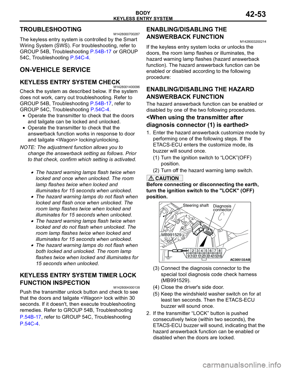
1. Enter the hazard answerback customize mode by
performing one of the following steps. If the
ETACS-ECU enters the customize mode, its
buzzer will sound once.
(1) Turn the ignition switch to “LOCK”(OFF)
position.
(2) Turn off the hazard warning lamp switch.
CAUTION
Before connecting or disconnecting the earth,
turn the ignition switch to the "LOCK" (OFF)
position.
(3) Connect the diagnosis connector to the
special tool diagnosis code check harness
(MB991529).
(4) Close the driver's side door.
(5) Keep the windshield washer switch on for at
least ten seconds. Then the ETACS-ECU
buzzer will sound once.
2. If the transmitter “LOCK” button is pushed
consecutively twice (within two seconds), the
ETACS-ECU buzzer will sound, indicating that the
hazard answerback function can be enabled or
disabled when the doors are locked.
AC305133AB
Diagnosis
connector
MB991529Steering shaft
Page 332 of 788
KEYLESS ENTRY SYSTEM
BODY42-54
•Enable the hazard answerback function
when the doors are locked: The
ETACS-ECU buzzer will sound once.
•Disable the hazard answerback function
when the doors are locked: The
ETACS-ECU buzzer will sound twice.
3. If the transmitter “UNLOCK” button is pushed
consecutively twice (within two seconds), the
ETACS-ECU buzzer will sound, indicating that the
hazard answerback function can be enabled or
disabled when the doors are unlocked.
•Enable the hazard answerback function
when the doors are unlocked: The
ETACS-ECU buzzer will sound once.
•Disable the hazard answerback function
when the doors are unlocked: The
ETACS-ECU buzzer will sound twice.
4. Exit the hazard answerback customize mode by
observing one of the following steps.
(1) Disconnect diagnosis connector terminal (1)
form the earth.
(2) Turn the ignition switch to position other then
“LOCK”(OFF), or remove the ignition key.
(3) Open the driver's side door.
(4) Any other warning buzzer output occurs.
NOTE: If any operation is not done for at least three
minutes after the ETACS-ECU has entered the
customize mode, the hazard answerback customize
mode will be canceled automatically.
connector>
1. Enter the hazard answerback customize mode by
performing one of the following steps. If the
ETACS-ECU enters the customize mode, its
buzzer will sound once.
(1) Turn the ignition switch to “LOCK”(OFF)
position.
(2) Turn off the hazard warning lamp switch.
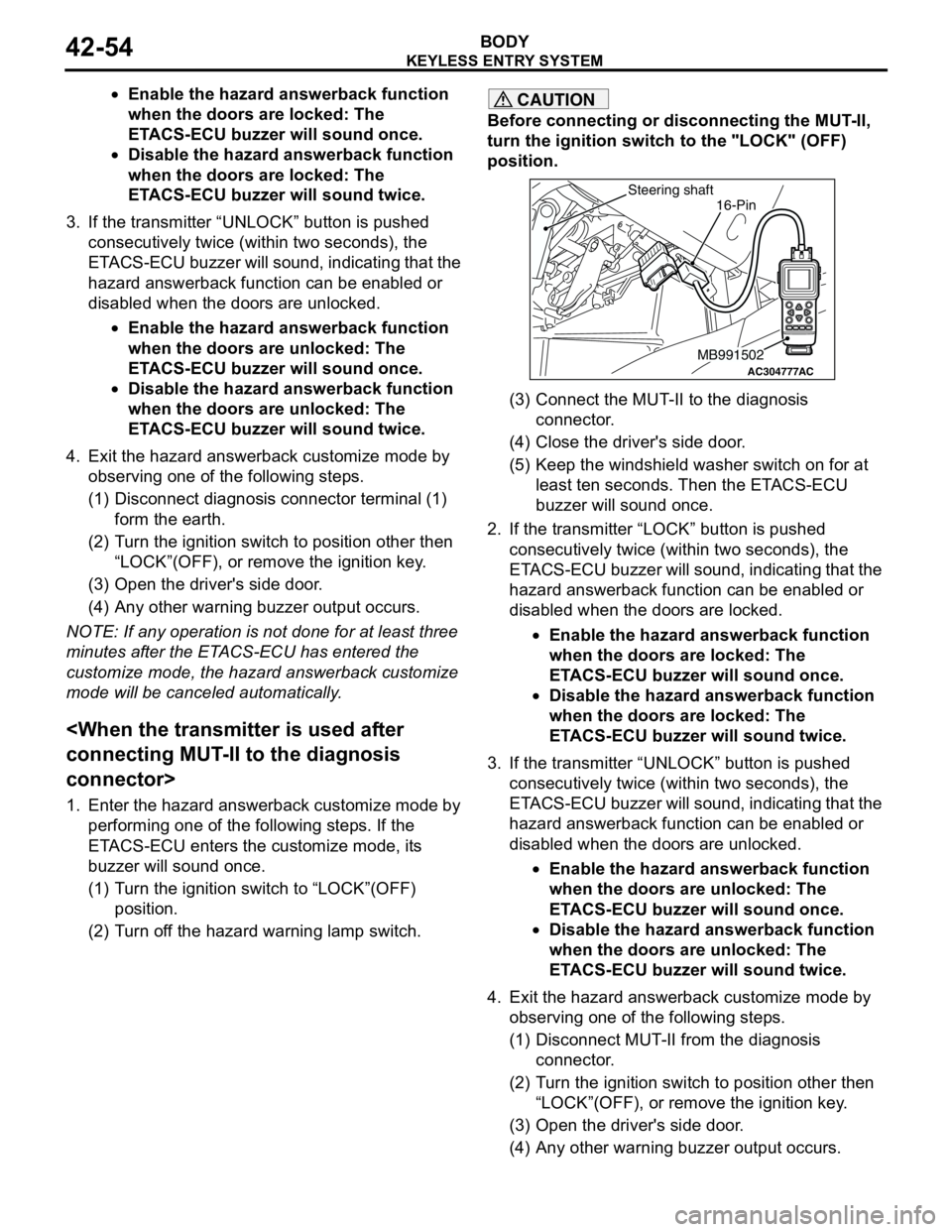
CAUTION
Before connecting or disconnecting the MUT-II,
turn the ignition switch to the "LOCK" (OFF)
position.
(3) Connect the MUT-II to the diagnosis
connector.
(4) Close the driver's side door.
(5) Keep the windshield washer switch on for at
least ten seconds. Then the ETACS-ECU
buzzer will sound once.
2. If the transmitter “LOCK” button is pushed
consecutively twice (within two seconds), the
ETACS-ECU buzzer will sound, indicating that the
hazard answerback function can be enabled or
disabled when the doors are locked.
•Enable the hazard answerback function
when the doors are locked: The
ETACS-ECU buzzer will sound once.
•Disable the hazard answerback function
when the doors are locked: The
ETACS-ECU buzzer will sound twice.
3. If the transmitter “UNLOCK” button is pushed
consecutively twice (within two seconds), the
ETACS-ECU buzzer will sound, indicating that the
hazard answerback function can be enabled or
disabled when the doors are unlocked.
•Enable the hazard answerback function
when the doors are unlocked: The
ETACS-ECU buzzer will sound once.
•Disable the hazard answerback function
when the doors are unlocked: The
ETACS-ECU buzzer will sound twice.
4. Exit the hazard answerback customize mode by
observing one of the following steps.
(1) Disconnect MUT-II from the diagnosis
connector.
(2) Turn the ignition switch to position other then
“LOCK”(OFF), or remove the ignition key.
(3) Open the driver's side door.
(4) Any other warning buzzer output occurs.
AC304777
Steering shaft
ACMB991502
16-Pin