checking oil MITSUBISHI LANCER 2005 Workshop Manual
[x] Cancel search | Manufacturer: MITSUBISHI, Model Year: 2005, Model line: LANCER, Model: MITSUBISHI LANCER 2005Pages: 788, PDF Size: 45.98 MB
Page 81 of 788

CHARGING SYSTEM
ENGINE ELECTRICAL16-17
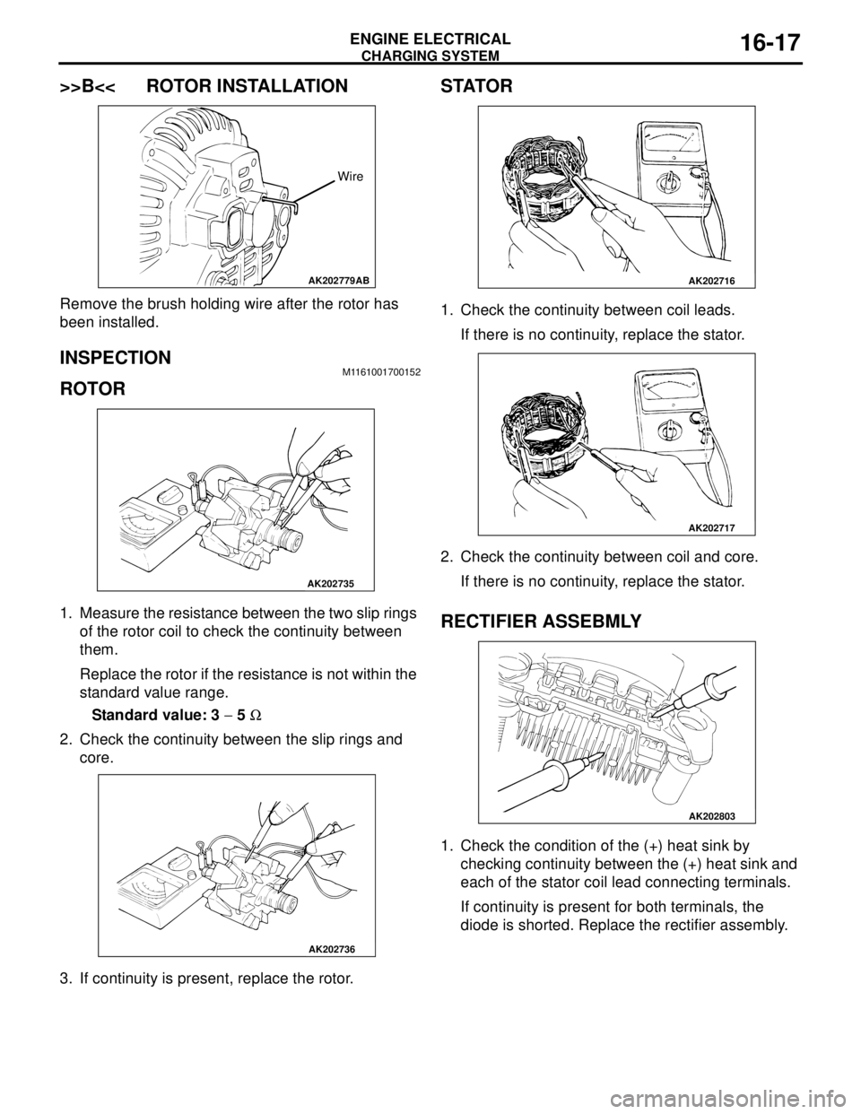
>>B<< ROTOR INSTALLATION
Remove the brush holding wire after the rotor has
been installed.
INSPECTION M1161001700152
ROTOR
1. Measure the resistance between the two slip rings
of the rotor coil to check the continuity between
them.
Replace the rotor if the resistance is not within the
standard value range.
Standard value: 3 − 5 Ω
2. Check the continuity between the slip rings and
core.
3. If continuity is present, replace the rotor.
STATOR
1. Check the continuity between coil leads.
If there is no continuity, replace the stator.
2. Check the continuity between coil and core.
If there is no continuity, replace the stator.
RECTIFIER ASSEBMLY
1. Check the condition of the (+) heat sink by
checking continuity between the (+) heat sink and
each of the stator coil lead connecting terminals.
If continuity is present for both terminals, the
diode is shorted. Replace the rectifier assembly.
AK202779
Wire
AB
AK202735
AK202736
AK202716
AK202717
AK202803
Page 82 of 788

CHARGING SYSTEM
ENGINE ELECTRICAL16-18
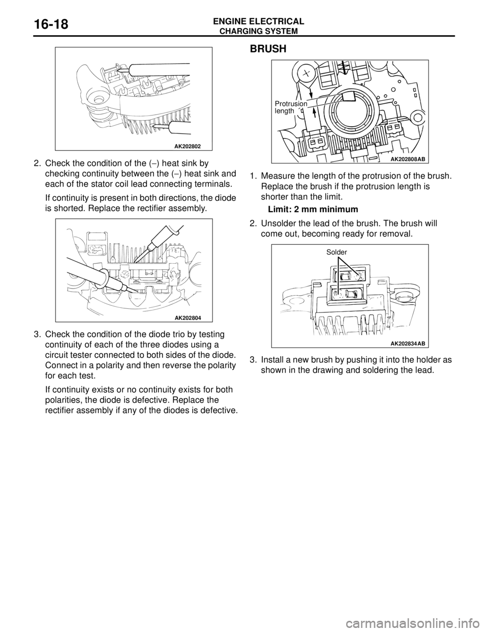
2. Check the condition of the (−) heat sink by
checking continuity between the (−) heat sink and
each of the stator coil lead connecting terminals.
If continuity is present in both directions, the diode
is shorted. Replace the rectifier assembly.
3. Check the condition of the diode trio by testing
continuity of each of the three diodes using a
circuit tester connected to both sides of the diode.
Connect in a polarity and then reverse the polarity
for each test.
If continuity exists or no continuity exists for both
polarities, the diode is defective. Replace the
rectifier assembly if any of the diodes is defective.
BRUSH
1. Measure the length of the protrusion of the brush.
Replace the brush if the protrusion length is
shorter than the limit.
Limit: 2 mm minimum
2. Unsolder the lead of the brush. The brush will
come out, becoming ready for removal.
3. Install a new brush by pushing it into the holder as
shown in the drawing and soldering the lead.
AK202802
AK202804
AK202808
Protrusion
length
AB
AK202834
Solder
AB
Page 237 of 788

GENERAL INFORMATION
POWER STEERING37-3
GENERAL INFORMATION
M1372000100337
Power steering has been adopted in all vehicles to
make the steering system easier to handle.
FEATURES
•A 4-spoke steering wheel is used.
•MOMO leather-wrapped 3-spoke steering wheel
is used.
•A steering column has a shock absorbing
mechanism and a tilt steering mechanism.•Integral-type rack and pinion gear with high
rigidity and excellent response is used.
•A vane type pump with a fluid flow rate control
system which change steering effort according to
the engine speed is used.
•The separate plastic resin oil reservoir is used to
reduce weight and to make the fluid level
checking easier.
SPECIFICATIONS
Item Comfort Sport
Steering
wheelType 4-spoke type MOMO leather-wrapped
3-spoke type
Outside diameter mm 380 365
Maximum number of turns 3.19 2.86
3.08
Steering
columnColumn mechanism Shock absorbing mechanism and Tilt steering mechanism
Power steering type Integral type
Oil pump Type Vane pump
Basic discharge amount cm
3/rev.7.2 <1300, 1600>
8.1 <2000>7.2 <1300, 1600>
8.1 <2000>
Relief pressure MPa 8.8 8.8
Reservoir type Separate type (plastic)
Pressure switch Equipped
Steering
gearType Rack and pinion
Stroke ratio (Rack stroke/Steering
wheel maximum turning radius)45.74 45.74
Rack stroke mm 146 131
141
Page 248 of 788

ON-VEHICLE SERVICE
POWER STEERING37-14
CAUTION
Perform air bleeding only while cranking the
engine. If air bleeding is performed while the
engine is running, air could enter the fluid.
During air bleeding, refill the steering fluid
supply so that the level never falls below the
"MIN" mark on the oil reservoir.
3. Turn the steering wheel all the way to the left and
right five or six times while using the starter motor
to crank the engine intermittently several times
(for 15 to 20 seconds).
4. Connect the ignition coil connectors (Refer to
GROUP 16, Ignition Coil P.16-38 or P.16-39).
5. Start the engine (idling).
6. Turn the steering wheel to the left and right until
there are no air bubbles in the oil reservoir.
7. Confirm that the fluid is not milky, and that the
level is between "MAX" and "MIN" marks.
8. Confirm that there is very little change in the fluid
level when the steering wheel is turned left and
right.
CAUTION
If the fluid level rises suddenly after the engine is
stopped, the air has not been completely bled. If
air bleeding is not complete, there will be
abnormal noises from the pump and the
flow-control valve, and this condition could
cause reduce the life of the power steering
components.
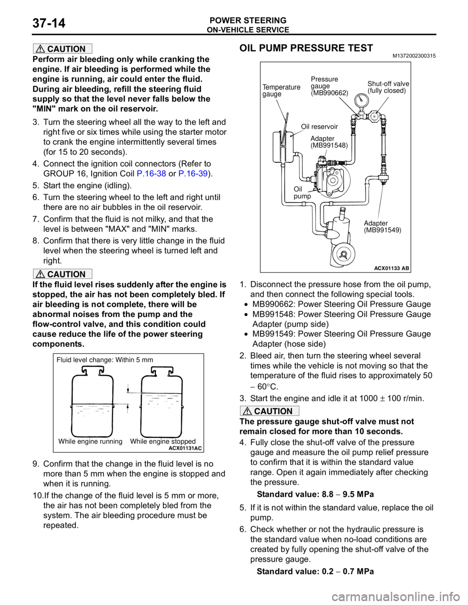
9. Confirm that the change in the fluid level is no
more than 5 mm when the engine is stopped and
when it is running.
10.If the change of the fluid level is 5 mm or more,
the air has not been completely bled from the
system. The air bleeding procedure must be
repeated.
OIL PUMP PRESSURE TESTM1372002300315
1. Disconnect the pressure hose from the oil pump,
and then connect the following special tools.
•MB990662: Power Steering Oil Pressure Gauge
•MB991548: Power Steering Oil Pressure Gauge
Adapter (pump side)
•MB991549: Power Steering Oil Pressure Gauge
Adapter (hose side)
2. Bleed air, then turn the steering wheel several
times while the vehicle is not moving so that the
temperature of the fluid rises to approximately 50
− 60°C.
3. Start the engine and idle it at 1000 ± 100 r/min.
CAUTION
The pressure gauge shut-off valve must not
remain closed for more than 10 seconds.
4. Fully close the shut-off valve of the pressure
gauge and measure the oil pump relief pressure
to confirm that it is within the standard value
range. Open it again immediately after checking
the pressure.
Standard value: 8.8 − 9.5 MPa
5. If it is not within the standard value, replace the oil
pump.
6. Check whether or not the hydraulic pressure is
the standard value when no-load conditions are
created by fully opening the shut-off valve of the
pressure gauge.
Standard value: 0.2 − 0.7 MPa
ACX01131While engine running While engine stoppedAC
Fluid level change: Within 5 mm
ACX01133
Temperature
gauge
Oil reservoir
Adapter
(MB991548)
Oil
pump
Adapter
(MB991549)
AB
Shut-off valve
(fully closed) Pressure
gauge
(MB990662)
Page 556 of 788

ON-VEHICLE SERVICE
HEATER, AIR CONDITIONER AND VENTILATION55-72
25.After charging with refrigerant, turn the handle of
the adaptor valve back all the way (valve closed).
26.Tighten the charging valve handle (valve closed).
Remove the quick joint (for low-pressure) from the
low-pressure service valve.
27.Remove the service can.
NOTE: If the service can is not emptied
completely, keep the handles of the charging
valve and adaptor valve closed for the next
charging.
CORRECTING LOW REFRIGERANT
LEVEL IN CASE THE SERVICE CAN IN
USED
M1552014600100
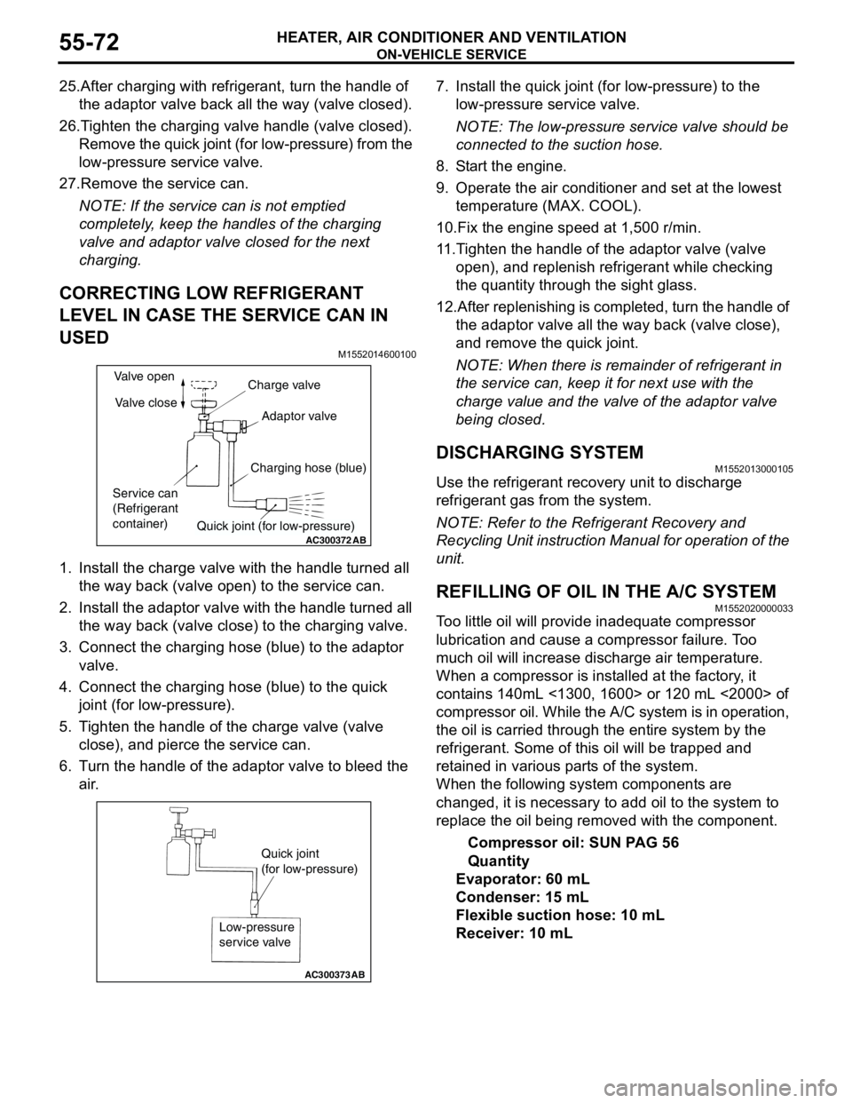
1. Install the charge valve with the handle turned all
the way back (valve open) to the service can.
2. Install the adaptor valve with the handle turned all
the way back (valve close) to the charging valve.
3. Connect the charging hose (blue) to the adaptor
valve.
4. Connect the charging hose (blue) to the quick
joint (for low-pressure).
5. Tighten the handle of the charge valve (valve
close), and pierce the service can.
6. Turn the handle of the adaptor valve to bleed the
air.7. Install the quick joint (for low-pressure) to the
low-pressure service valve.
NOTE: The low-pressure service valve should be
connected to the suction hose.
8. Start the engine.
9. Operate the air conditioner and set at the lowest
temperature (MAX. COOL).
10.Fix the engine speed at 1,500 r/min.
11.Tighten the handle of the adaptor valve (valve
open), and replenish refrigerant while checking
the quantity through the sight glass.
12.After replenishing is completed, turn the handle of
the adaptor valve all the way back (valve close),
and remove the quick joint.
NOTE: When there is remainder of refrigerant in
the service can, keep it for next use with the
charge value and the valve of the adaptor valve
being closed.
DISCHARGING SYSTEMM1552013000105
Use the refrigerant recovery unit to discharge
refrigerant gas from the system.
NOTE: Refer to the Refrigerant Recovery and
Recycling Unit instruction Manual for operation of the
unit.
REFILLING OF OIL IN THE A/C SYSTEMM1552020000033
Too little oil will provide inadequate compressor
lubrication and cause a compressor failure. Too
much oil will increase discharge air temperature.
When a compressor is installed at the factory, it
contains 140mL <1300, 1600> or 120 mL <2000> of
compressor oil. While the A/C system is in operation,
the oil is carried through the entire system by the
refrigerant. Some of this oil will be trapped and
retained in various parts of the system.
When the following system components are
changed, it is necessary to add oil to the system to
replace the oil being removed with the component.
Compressor oil: SUN PAG 56
Quantity
Evaporator: 60 mL
Condenser: 15 mL
Flexible suction hose: 10 mL
Receiver: 10 mL
AC300372
AB
Valve open
Valve close
Service can
(Refrigerant
container)Charge valve
Adaptor valve
Charging hose (blue)
Quick joint (for low-pressure)
AC300373
Quick joint
(for low-pressure)
Low-pressure
service valve
AB