exterior MITSUBISHI LANCER 2005 Workshop Manual
[x] Cancel search | Manufacturer: MITSUBISHI, Model Year: 2005, Model line: LANCER, Model: MITSUBISHI LANCER 2005Pages: 788, PDF Size: 45.98 MB
Page 1 of 788
GROUP INDEX
00General . . . . . . . . . . . . . . . . . . . . . . . .
11Engine. . . . . . . . . . . . . . . . . . . . . . . . .
12Engine Lubrication . . . . . . . . . . . . . .
13Fuel . . . . . . . . . . . . . . . . . . . . . . . . . . .
14Engine Cooling . . . . . . . . . . . . . . . . .
15Intake and Exhaust . . . . . . . . . . . . . .
16Engine Electrical . . . . . . . . . . . . . . . .
17Engine and Emission Control . . . . .
21Clutch . . . . . . . . . . . . . . . . . . . . . . . . .
22Manual Transmission . . . . . . . . . . . .
23Automatic Transmission. . . . . . . . . .
26Front Axle . . . . . . . . . . . . . . . . . . . . . .
27Rear Axle . . . . . . . . . . . . . . . . . . . . . .
31Wheel and Tyre . . . . . . . . . . . . . . . . .
32Power Plant Mount . . . . . . . . . . . . . .
33Front Suspension . . . . . . . . . . . . . . .
34Rear Suspension . . . . . . . . . . . . . . . .
35Service Brakes . . . . . . . . . . . . . . . . . .
36Parking Brakes . . . . . . . . . . . . . . . . .
37Power Steering . . . . . . . . . . . . . . . . .
42Body . . . . . . . . . . . . . . . . . . . . . . . . . .
51Exterior . . . . . . . . . . . . . . . . . . . . . . . .
52 . . . . . . . . . .
54Chassis Electrical . . . . . . . . . . . . . . .
55 . . . . . . .
70Component Locations. . . . . . . . . . . .
80Configration Diagrams . . . . . . . . . . .
90Circuit Diagrams . . . . . . . . . . . . . . . .
LANCER /
LANCER WAGON
WORKSHOP MANUAL
FOREWORD
This Workshop manual contains procedures for
service mechanics, including removal, disassembly,
inspection, adjustment, reassembly and installation.
Use the following manuals in combination with this
manual as required.
TECHNICAL INFORMATION MANUAL
PYME0302
PYME0302-A
WORKSHOP MANUAL
CHASSIS GROUP PWME0302
BODY REPAIR MANUAL
PBME0302
PBME0302-A
PARTS CATALOGUE
B606K005A_
All information, illustrations and product descriptions
contained in this manual are current as at the time of
publication. We, however, reserve the right to make
changes at any time without prior notice or obligation.
Mitsubishi Motors Corporation May 2004
Heater, Air Conditioner and
Ventilation Interior and Supplemental
Restraint System (SRS)
Page 339 of 788
51-1
GROUP 51
EXTERIOR
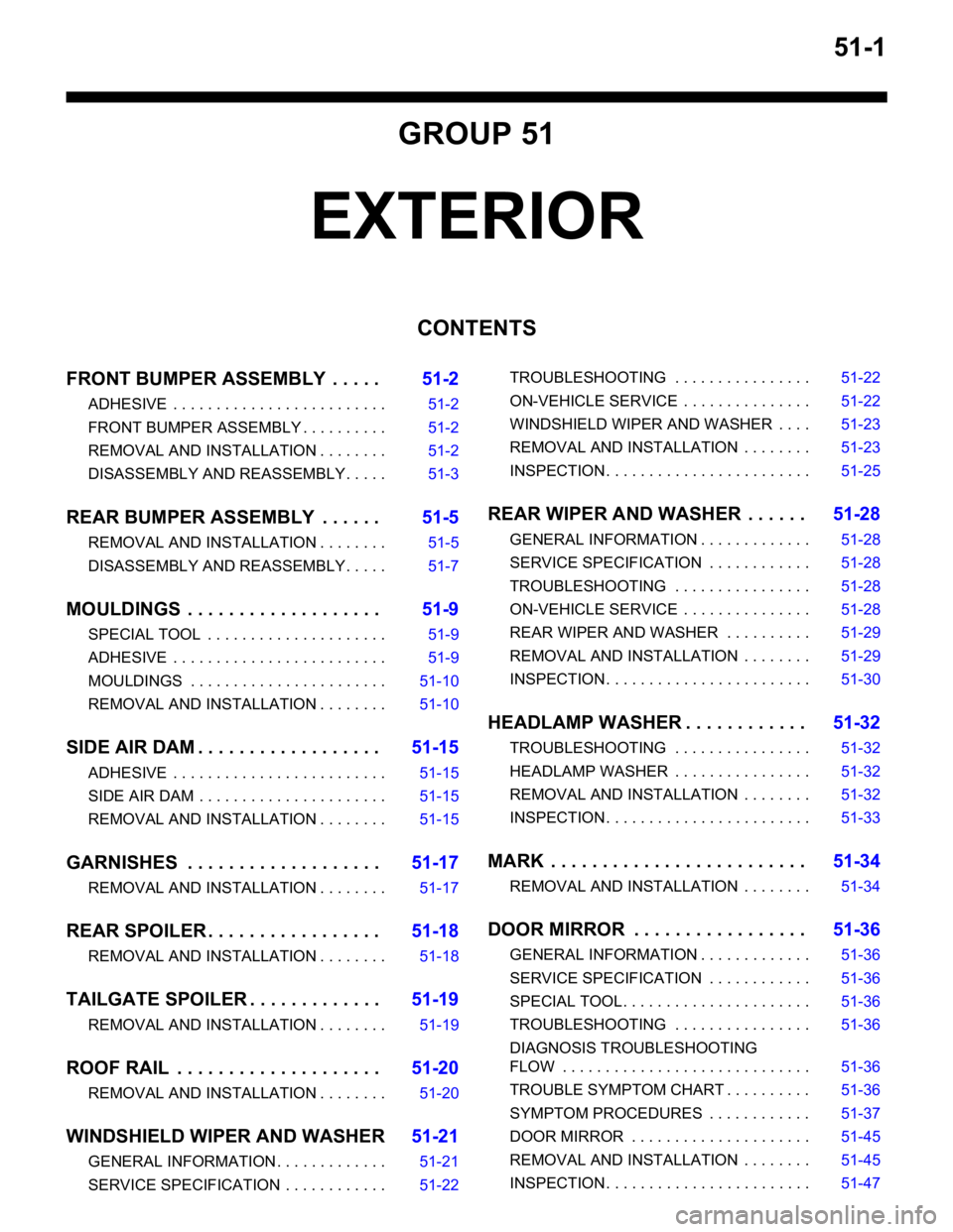
CONTENTS
FRONT BUMPER ASSEMBLY . . . . .51-2
ADHESIVE . . . . . . . . . . . . . . . . . . . . . . . . . 51-2
FRONT BUMPER ASSEMBLY . . . . . . . . . . 51-2
REMOVAL AND INSTALLATION . . . . . . . . 51-2
DISASSEMBLY AND REASSEMBLY . . . . . 51-3
REAR BUMPER ASSEMBLY . . . . . .51-5
REMOVAL AND INSTALLATION . . . . . . . . 51-5
DISASSEMBLY AND REASSEMBLY . . . . . 51-7
MOULDINGS . . . . . . . . . . . . . . . . . . .51-9
SPECIAL TOOL . . . . . . . . . . . . . . . . . . . . . 51-9
ADHESIVE . . . . . . . . . . . . . . . . . . . . . . . . . 51-9
MOULDINGS . . . . . . . . . . . . . . . . . . . . . . . 51-10
REMOVAL AND INSTALLATION . . . . . . . . 51-10
SIDE AIR DAM . . . . . . . . . . . . . . . . . .51-15
ADHESIVE . . . . . . . . . . . . . . . . . . . . . . . . . 51-15
SIDE AIR DAM . . . . . . . . . . . . . . . . . . . . . . 51-15
REMOVAL AND INSTALLATION . . . . . . . . 51-15
GARNISHES . . . . . . . . . . . . . . . . . . .51-17
REMOVAL AND INSTALLATION . . . . . . . . 51-17
REAR SPOILER . . . . . . . . . . . . . . . . .51-18
REMOVAL AND INSTALLATION . . . . . . . . 51-18
TAILGATE SPOILER . . . . . . . . . . . . .51-19
REMOVAL AND INSTALLATION . . . . . . . . 51-19
ROOF RAIL . . . . . . . . . . . . . . . . . . . .51-20
REMOVAL AND INSTALLATION . . . . . . . . 51-20
WINDSHIELD WIPER AND WASHER51-21
GENERAL INFORMATION . . . . . . . . . . . . . 51-21
SERVICE SPECIFICATION . . . . . . . . . . . . 51-22TROUBLESHOOTING . . . . . . . . . . . . . . . . 51-22
ON-VEHICLE SERVICE . . . . . . . . . . . . . . . 51-22
WINDSHIELD WIPER AND WASHER . . . . 51-23
REMOVAL AND INSTALLATION . . . . . . . . 51-23
INSPECTION . . . . . . . . . . . . . . . . . . . . . . . . 51-25
REAR WIPER AND WASHER . . . . . .51-28
GENERAL INFORMATION . . . . . . . . . . . . . 51-28
SERVICE SPECIFICATION . . . . . . . . . . . . 51-28
TROUBLESHOOTING . . . . . . . . . . . . . . . . 51-28
ON-VEHICLE SERVICE . . . . . . . . . . . . . . . 51-28
REAR WIPER AND WASHER . . . . . . . . . . 51-29
REMOVAL AND INSTALLATION . . . . . . . . 51-29
INSPECTION . . . . . . . . . . . . . . . . . . . . . . . . 51-30
HEADLAMP WASHER . . . . . . . . . . . .51-32
TROUBLESHOOTING . . . . . . . . . . . . . . . . 51-32
HEADLAMP WASHER . . . . . . . . . . . . . . . . 51-32
REMOVAL AND INSTALLATION . . . . . . . . 51-32
INSPECTION . . . . . . . . . . . . . . . . . . . . . . . . 51-33
MARK . . . . . . . . . . . . . . . . . . . . . . . . .51-34
REMOVAL AND INSTALLATION . . . . . . . . 51-34
DOOR MIRROR . . . . . . . . . . . . . . . . .51-36
GENERAL INFORMATION . . . . . . . . . . . . . 51-36
SERVICE SPECIFICATION . . . . . . . . . . . . 51-36
SPECIAL TOOL. . . . . . . . . . . . . . . . . . . . . . 51-36
TROUBLESHOOTING . . . . . . . . . . . . . . . . 51-36
DIAGNOSIS TROUBLESHOOTING
FLOW . . . . . . . . . . . . . . . . . . . . . . . . . . . . . 51-36
TROUBLE SYMPTOM CHART . . . . . . . . . . 51-36
SYMPTOM PROCEDURES . . . . . . . . . . . . 51-37
DOOR MIRROR . . . . . . . . . . . . . . . . . . . . . 51-45
REMOVAL AND INSTALLATION . . . . . . . . 51-45
INSPECTION . . . . . . . . . . . . . . . . . . . . . . . . 51-47
Page 340 of 788
FRONT BUMPER ASSEMBLY
EXTERIOR51-2
FRONT BUMPER ASSEMBLY
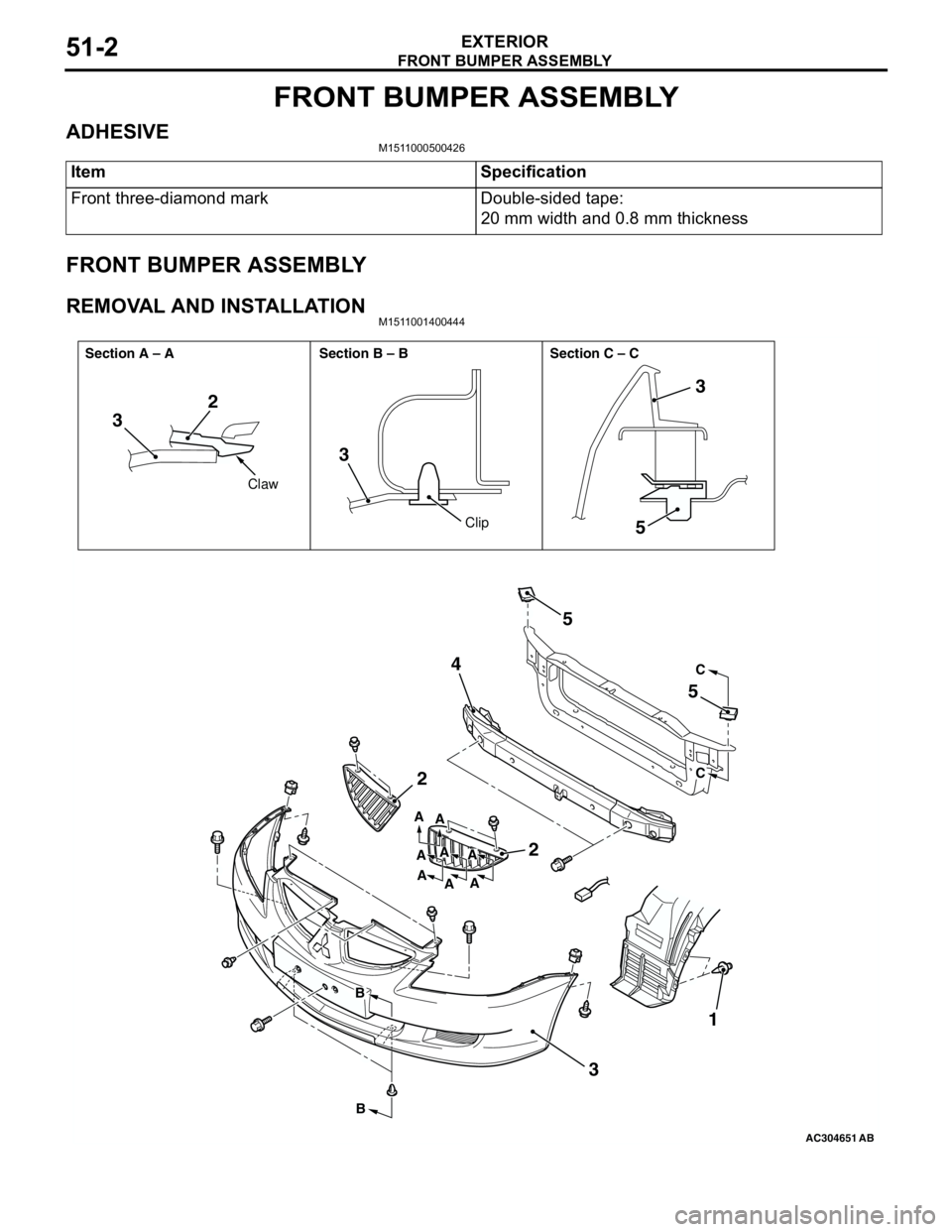
ADHESIVEM1511000500426
FRONT BUMPER ASSEMBLY
REMOVAL AND INSTALLATIONM1511001400444
Item Specification
Front three-diamond mark Double-sided tape:
20 mm width and 0.8 mm thickness
AC304651AB
32
3
5
2
2 45
5
31
3
C
C
B
BA
A
A A A
A
AA
Claw
Clip Section A – A Section B – B Section C – C
Page 341 of 788
FRONT BUMPER ASSEMBLY
EXTERIOR51-3
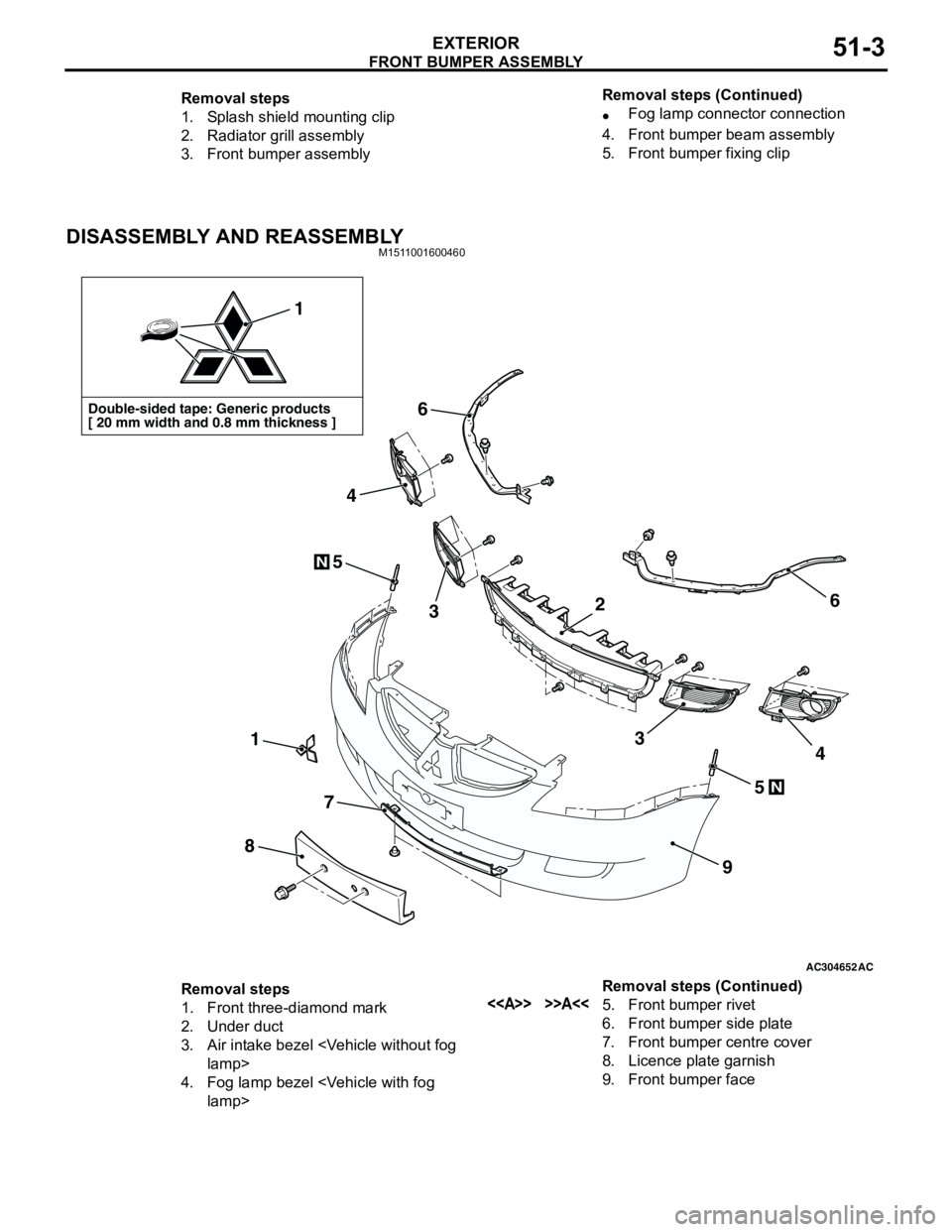
DISASSEMBLY AND REASSEMBLYM1511001600460
Removal steps
1. Splash shield mounting clip
2. Radiator grill assembly
3. Front bumper assembly•Fog lamp connector connection
4. Front bumper beam assembly
5. Front bumper fixing clip Removal steps (Continued)
AC304652AC
Double-sided tape: Generic products
[ 20 mm width and 0.8 mm thickness ]
1
1
8
7
9
6
6
5
5
3
4
34
N
N
2
Removal steps
1. Front three-diamond mark
2. Under duct
3. Air intake bezel
4. Fog lamp bezel
6. Front bumper side plate
7. Front bumper centre cover
8. Licence plate garnish
9. Front bumper face Removal steps (Continued)
Page 342 of 788
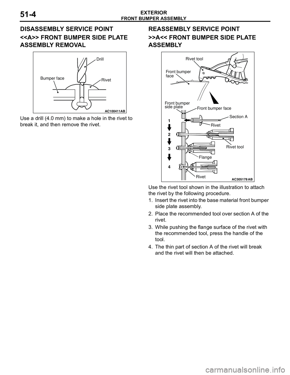
Page 343 of 788
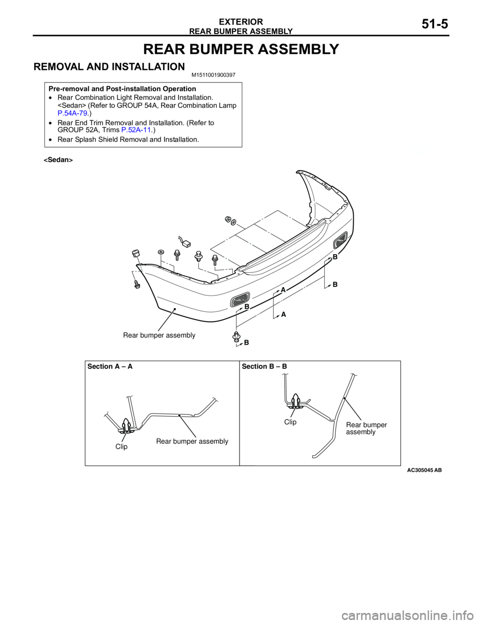
REAR BUMPER ASSEMBLY
EXTERIOR51-5
REAR BUMPER ASSEMBLY
REMOVAL AND INSTALLATIONM1511001900397
Pre-removal and Post-installation Operation
•Rear Combination Light Removal and Installation.
P.54A-79.)
•Rear End Trim Removal and Installation. (Refer to
GROUP 52A, Trims P.52A-11.)
•Rear Splash Shield Removal and Installation.
AC300413
AC305045
ClipRear bumper assemblyRear bumper assembly Section A – A Section B – B
ClipRear bumper
assembly
AB
B
BA
AB
B
Page 344 of 788
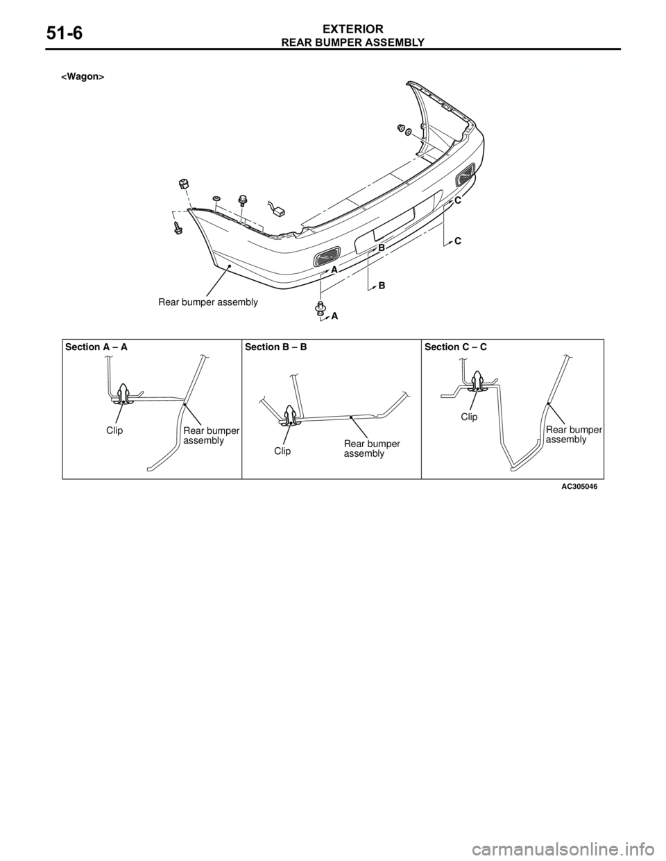
REAR BUMPER ASSEMBLY
EXTERIOR51-6
AC300199
AC305046
A
A
B
BC
C
Clip
Clip
Rear bumper
assembly
Clip Section A – A Section B – B Section C – C
Rear bumper
assembly
Rear bumper
assembly
Rear bumper assembly
Page 345 of 788
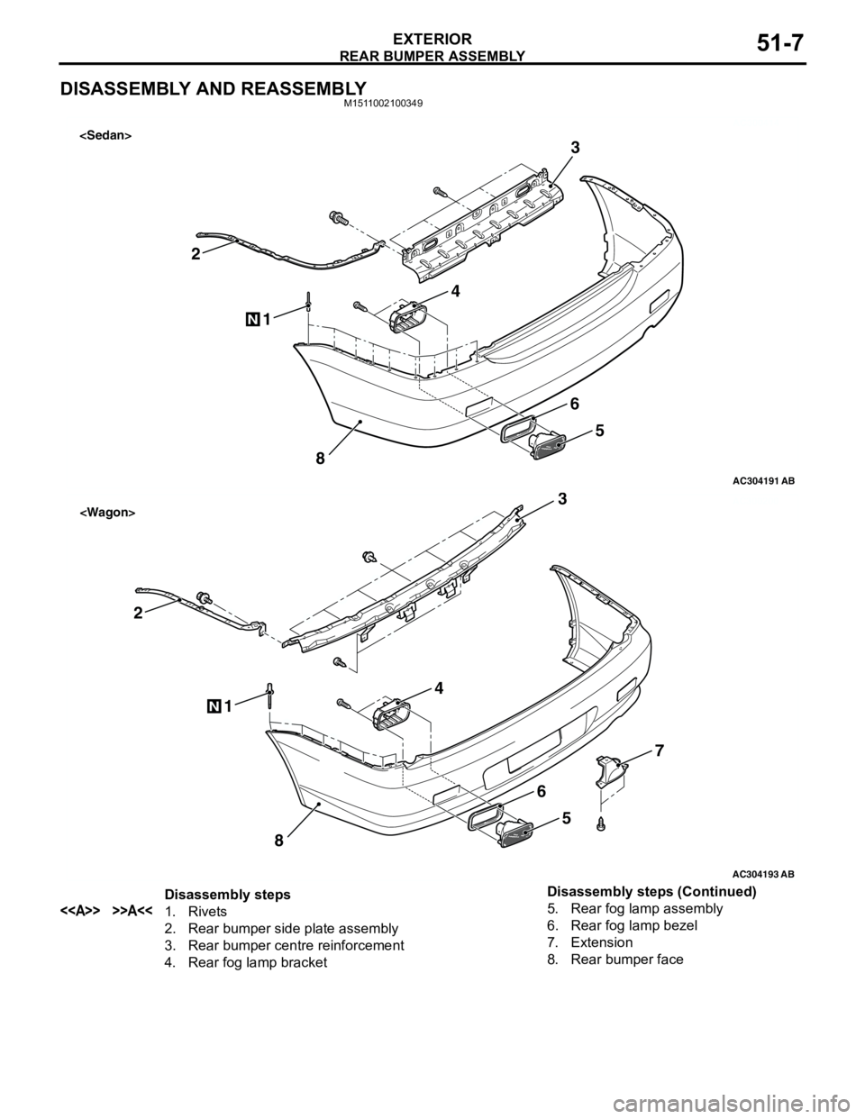
REAR BUMPER ASSEMBLY
EXTERIOR51-7
DISASSEMBLY AND REASSEMBLYM1511002100349
AC300414
AC304191
1
2
8
N
3
4
5
6
AB
AC300200
AC304193
1
2
8
N
3
4
5
7
6
AB
Disassembly steps
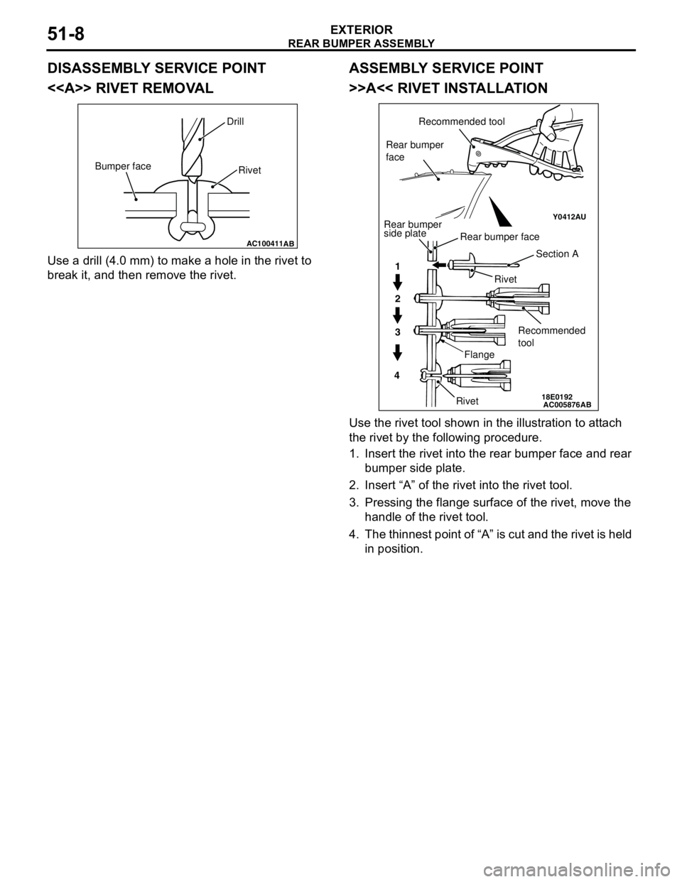
<> >>A<<1. Rivets
2. Rear bumper side plate assembly
3. Rear bumper centre reinforcement
4. Rear fog lamp bracket5. Rear fog lamp assembly
6. Rear fog lamp bezel
7. Extension
8. Rear bumper face Disassembly steps (Continued)
Page 346 of 788
Page 347 of 788
MOULDINGS
EXTERIOR51-9
MOULDINGS
SPECIAL TOOLM1511000601136
ADHESIVEM1511000500749
Tool Number Name Application
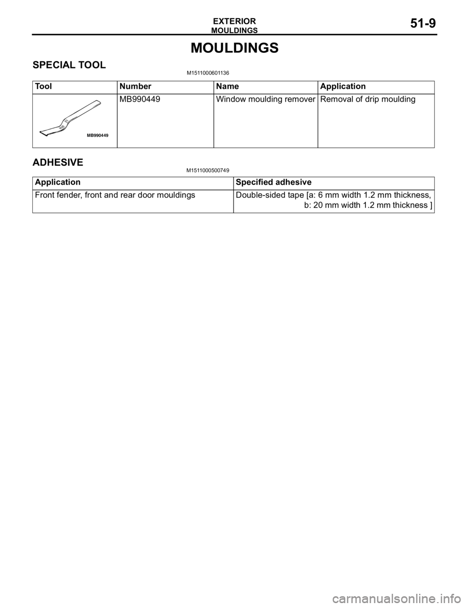
MB990449 Window moulding remover Removal of drip moulding
MB990449
Application Specified adhesive
Front fender, front and rear door mouldings Double-sided tape [a: 6 mm width 1.2 mm thickness,
b: 20 mm width 1.2 mm thickness ]