height MITSUBISHI LANCER 2005 Workshop Manual
[x] Cancel search | Manufacturer: MITSUBISHI, Model Year: 2005, Model line: LANCER, Model: MITSUBISHI LANCER 2005Pages: 788, PDF Size: 45.98 MB
Page 42 of 788
THERMOSTAT
ENGINE COOLING14-28
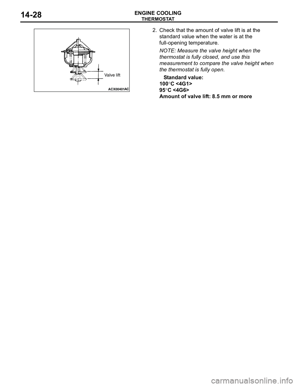
2. Check that the amount of valve lift is at the
standard value when the water is at the
full-opening temperature.
NOTE: Measure the valve height when the
thermostat is fully closed, and use this
measurement to compare the valve height when
the thermostat is fully open.
Standard value:
100°C <4G1>
95°C <4G6>
Amount of valve lift: 8.5 mm or more
ACX00401AC
Valve lift
Page 73 of 788
CHARGING SYSTEM
ENGINE ELECTRICAL16-9
WAVEFORM CHECK USING AN OSCILLOSCOPEM1161001200124
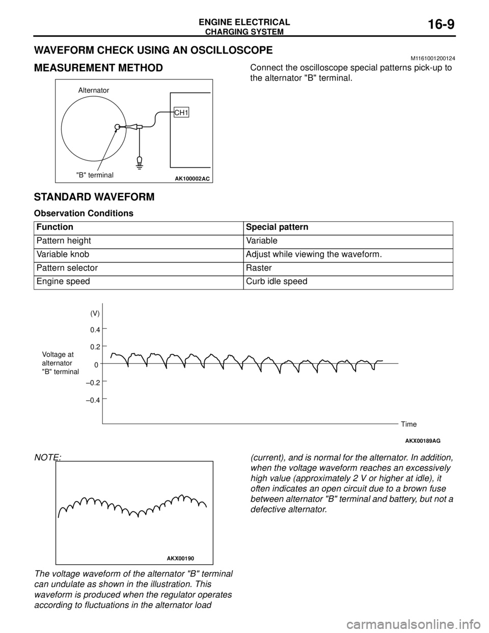
MEASUREMENT METHODConnect the oscilloscope special patterns pick-up to
the alternator "B" terminal.
STANDARD WAVEFORM
Observation Conditions
NOTE:
The voltage waveform of the alternator "B" terminal
can undulate as shown in the illustration. This
waveform is produced when the regulator operates
according to fluctuations in the alternator load (current), and is normal for the alternator. In addition,
when the voltage waveform reaches an excessively
high value (approximately 2 V or higher at idle), it
often indicates an open circuit due to a brown fuse
between alternator "B" terminal and battery, but not a
defective alternator.
AK100002
Alternator
"B" terminalCH1
AC
Function Special pattern
Pattern height Variable
Variable knob Adjust while viewing the waveform.
Pattern selector Raster
Engine speed Curb idle speed
AKX00189
0.4 (V)
0.2
0
–0.2
–0.4 Voltage at
alternator
"B" terminal
Time
AG
AKX00190
Page 92 of 788
STARTING SYSTEM
ENGINE ELECTRICAL16-28
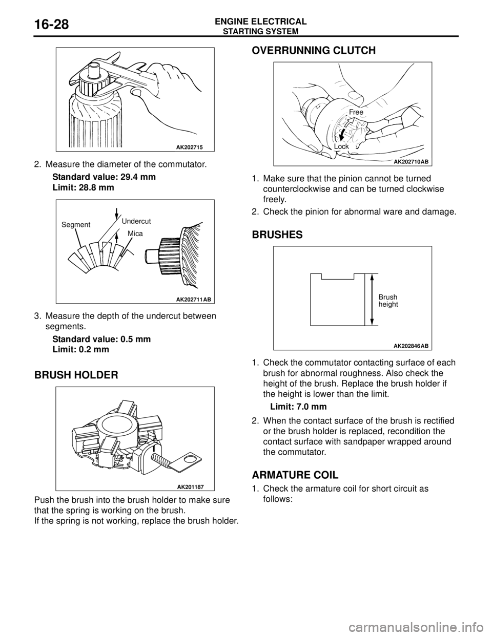
2. Measure the diameter of the commutator.
Standard value: 29.4 mm
Limit: 28.8 mm
3. Measure the depth of the undercut between
segments.
Standard value: 0.5 mm
Limit: 0.2 mm
BRUSH HOLDER
Push the brush into the brush holder to make sure
that the spring is working on the brush.
If the spring is not working, replace the brush holder.
OVERRUNNING CLUTCH
1. Make sure that the pinion cannot be turned
counterclockwise and can be turned clockwise
freely.
2. Check the pinion for abnormal ware and damage.
BRUSHES
1. Check the commutator contacting surface of each
brush for abnormal roughness. Also check the
height of the brush. Replace the brush holder if
the height is lower than the limit.
Limit: 7.0 mm
2. When the contact surface of the brush is rectified
or the brush holder is replaced, recondition the
contact surface with sandpaper wrapped around
the commutator.
ARMATURE COIL
1. Check the armature coil for short circuit as
follows:
AK202715
AK202711
SegmentUndercut
Mica
AB
AK201187
AK202710
Free
Lock
AB
AK202846
Brush
height
AB
Page 98 of 788
IGNITION SYSTEM
ENGINE ELECTRICAL16-34
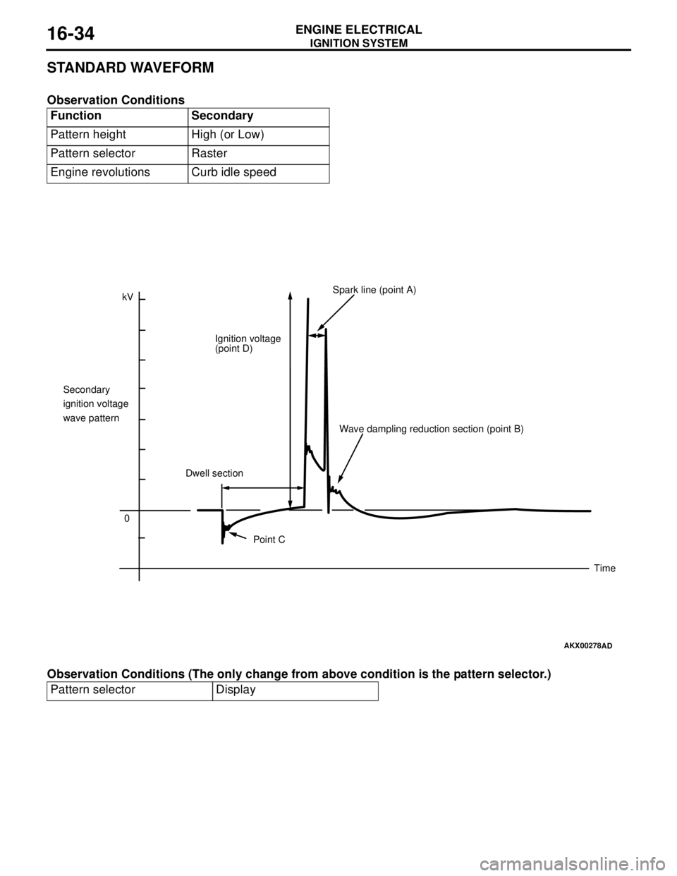
STANDARD WAVEFORM
Observation Conditions
Observation Conditions (The only change from above condition is the pattern selector.)Function Secondary
Pattern height High (or Low)
Pattern selector Raster
Engine revolutions Curb idle speed
Pattern selector Display
AKX00278
kV
0 Secondary
ignition voltage
wave patternIgnition voltage
(point D)Spark line (point A)
Dwell sectionWave dampling reduction section (point B)
Point C
Time
AD
Page 99 of 788
IGNITION SYSTEM
ENGINE ELECTRICAL16-35
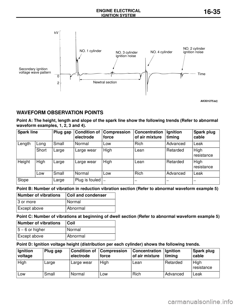
WAVEFORM OBSERVATION POINTS
Point A: The height, length and slope of the spark line show the following trends (Refer to abnormal
waveform examples, 1, 2, 3 and 4).
Point B: Number of vibration in reduction vibration section (Refer to abnormal waveform example 5)
Point C: Number of vibrations at beginning of dwell section (Refer to abnormal waveform example 5)
Point D: Ignition voltage height (distribution per each cylinder) shows the following trends.
AKX01275
kV
Secondary ignition
voltage wave pattern
0
2NO. 1 cylinder
NO. 3 cylinder
ignition noise
Newtral sectionNO. 4 cylinderNO. 2 cylinder
ignition noise
Time
AC
Spark line Plug gap Condition of
electrodeCompression
force Concentration
of air mixtureIgnition
timingSpark plug
cable
Length Long Small Normal Low Rich Advanced Leak
Short Large Large wear High Lean Retarded High
resistance
Height High Large Large wear High Lean Retarded High
resistance
Low Small Normal Low Rich Advanced Leak
Slope Large Plug is fouled
−− −−
Number of vibrations Coil and condenser
3 or more Normal
Except above Abnormal
Number of vibrations Coil
5 − 6 or higher Normal
Except above Abnormal
Ignition
voltagePlug gap Condition of
electrodeCompression
forceConcentration
of air mixtureIgnition
timingSpark plug
cable
High Large Large wear High Lean Retarded High
resistance
Low Small Normal Low Rich Advanced Leak
Page 279 of 788
42-1
GROUP 42
BODY
CONTENTS
HOOD . . . . . . . . . . . . . . . . . . . . .
42-3
ON-VEHICLE SERVICE. . . . . . . . .
42-3
ADJUSTMENT OF CLEARANCE
AROUND HOOD . . . . . . . . . . . . . . . . . . 42-3
ADJUSTMENT OF ALIGNMENT OF
HOOD STEPPED PORTION AND
HOOD STRIKER . . . . . . . . . . . . . . . . . . 42-3
ADJUSTMENT OF HOOD HEIGHT . . . 42-3
HOOD . . . . . . . . . . . . . . . . . . . . . . .42-4
REMOVAL AND INSTALLATION . . . . . 42-4
FENDER . . . . . . . . . . . . . . . . . . .42-5
SPECIAL TOOL . . . . . . . . . . . . . . .
42-5
FENDER . . . . . . . . . . . . . . . . . . . . .42-6
REMOVAL AND INSTALLATION . . . . . 42-6
FUEL FILLER LID . . . . . . . . . . .42-8
REMOVAL AND INSTALLATION .
42-8
STRUT TOWER BAR . . . . . . . .42-9
REMOVAL AND INSTALLATION .
42-9
WINDOW GLASS . . . . . . . . . . . 42-9
ADHESIVE . . . . . . . . . . . . . . . . . . .
42-9
SPECIAL TOOLS . . . . . . . . . . . . . .42-9
WINDOW REPAIR . . . . . . . . . . . . .42-10
WINDSHIELD . . . . . . . . . . . . . . . . .42-12
REMOVAL AND INSTALLATION . . . . . . 42-12
REAR WINDOW GLASS . . . . . . . .42-16
REMOVAL AND INSTALLATION . . . . . . 42-16
QUARTER WINDOW GLASS . . . .42-19
REMOVAL AND INSTALLATION . . . . . . 42-19
TAILGATE WINDOW GLASS . . . .42-22
REMOVAL AND INSTALLATION . . . . . . 42-22
DOOR . . . . . . . . . . . . . . . . . . . . 42-25
SERVICE SPECIFICATIONS . . . . .
42-25
SEALANT . . . . . . . . . . . . . . . . . . . .42-25
SPECIAL TOOLS . . . . . . . . . . . . . .42-25
Continued on next page
Page 280 of 788
42-2
TROUBLESHOOTING . . . . . . . . . .42-26
ON-VEHICLE SERVICE. . . . . . . . .42-27
DOOR FIT ADJUSTMENT. . . . . . . . . . . 42-27
DOOR WINDOW GLASS ADJUSTMENT42-28
GLASS SLIDING MECHANISM CHECK
AND ADJUSTMENT . . . . . . . . . . . . . . . 42-28
POWER WINDOW OPERATING
CURRENT CHECK . . . . . . . . . . . . . . . . 42-28
POWER WINDOW RELAY CHECK . . . 42-29
CIRCUIT BREAKER (INCORPORATED
IN THE POWER WINDOW MOTOR)
INSPECTION . . . . . . . . . . . . . . . . . . . . . 42-29
POWER WINDOW CHECK . . . . . . . . . . 42-29
CENTRAL DOOR LOCKING SYSTEM
INSPECTION . . . . . . . . . . . . . . . . . . . . . 42-29
DOOR OUTSIDE HANDLE PLAY
CHECK . . . . . . . . . . . . . . . . . . . . . . . . . 42-29
DOOR INSIDE HANDLE PLAY
ADJUSTMENT . . . . . . . . . . . . . . . . . . . . 42-30
DOOR ASSEMBLY . . . . . . . . . . . .42-31
REMOVAL AND INSTALLATION . . . . . 42-31
INSPECTION . . . . . . . . . . . . . . . . . . . . . 42-32
DOOR GLASS AND
REGULATOR . . . . . . . . . . . . . . . . .
42-32
REMOVAL AND INSTALLATION . . . . . 42-32
INSPECTION . . . . . . . . . . . . . . . . . . . . . 42-34
DOOR HANDLE AND LATCH . . . .42-36
REMOVAL AND INSTALLATION . . . . . 42-36
INSPECTION . . . . . . . . . . . . . . . . . . . . . 42-37
WINDOW GLASS RUNCHANNEL AND
DOOR OPENING
WEATHERSTRIP . . . . . . . . . . . . . .
42-39
REMOVAL AND INSTALLATION . . . . . 42-39
TRUNK LID . . . . . . . . . . . . . . . .42-41
SPECIAL TOOL . . . . . . . . . . . . . . .
42-41
ON-VEHICLE SERVICE. . . . . . . . .42-41
TRUNK LID ADJUSTMENT . . . . . . . . . . 42-41
ADJUSTMENT OF CLEARANCE
AROUND TRUNK LID . . . . . . . . . . . . . . 42-42
TRUNK LID STRIKER ADJUSTMENT . 42-42
TRUNK LID HEIGHT ADJUSTMENT . . 42-42
TRUNK LID . . . . . . . . . . . . . . . . . . .42-43
REMOVAL AND INSTALLATION . . . . . . 42-43
INSPECTION . . . . . . . . . . . . . . . . . . . . . 42-45
TAILGATE . . . . . . . . . . . . . . . . 42-46
SERVICE SPECIFICATIONS . . . . .
42-46
SEALANTS . . . . . . . . . . . . . . . . . . .42-46
SPECIAL TOOL . . . . . . . . . . . . . . .42-46
TROUBLESHOOTING . . . . . . . . . .42-46
ON-VEHICLE SERVICE . . . . . . . . .42-46
TAILGATE FIT ADJUSTMENT. . . . . . . . 42-46
TAILGATE HANDLE PLAY CHECK . . . . 42-47
TAILGATE . . . . . . . . . . . . . . . . . . .42-48
REMOVAL AND INSTALLATION . . . . . . 42-48
TAILGATE HANDLE AND
LATCH . . . . . . . . . . . . . . . . . . . . . .
42-50
REMOVAL AND INSTALLATION . . . . . . 42-50
INSPECTION . . . . . . . . . . . . . . . . . . . . . 42-51
KEYLESS ENTRY SYSTEM . . 42-51
SERVICE SPECIFICATIONS . . . . .
42-51
SPECIAL TOOLS . . . . . . . . . . . . . .42-52
TROUBLESHOOTING . . . . . . . . . .42-53
ON-VEHICLE SERVICE . . . . . . . . .42-53
KEYLESS ENTRY SYSTEM CHECK. . . 42-53
KEYLESS ENTRY SYSTEM TIMER
LOCK FUNCTION INSPECTION . . . . . . 42-53
ENABLING/DISABLING
THE ANSWERBACK FUNCTION . . . . . 42-53
HOW TO REGISTER SECRET CODE . 42-55
TRANSMITTER. . . . . . . . . . . . . . . .42-58
DISASSEMBLY AND REASSEMBLY . . 42-58
INSPECTION . . . . . . . . . . . . . . . . . . . . . 42-59
Page 281 of 788
HOOD
BODY42-3
HOOD
ON-VEHICLE SERVICE
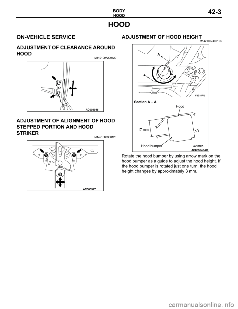
ADJUSTMENT OF CLEARANCE AROUND
HOOD
M1421007200129
ADJUSTMENT OF ALIGNMENT OF HOOD
STEPPED PORTION AND HOOD
STRIKER
M1421007300126
ADJUSTMENT OF HOOD HEIGHTM1421007400123
Rotate the hood bumper by using arrow mark on the
hood bumper as a guide to adjust the hood height. If
the hood bumper is rotated just one turn, the hood
height changes by approximately 3 mm.
AC005945
AC005947
Y0215AU
X0424CA
AC005948
AB
Section A – AA
A
Hood
Hood bumper 17 mm
Page 282 of 788
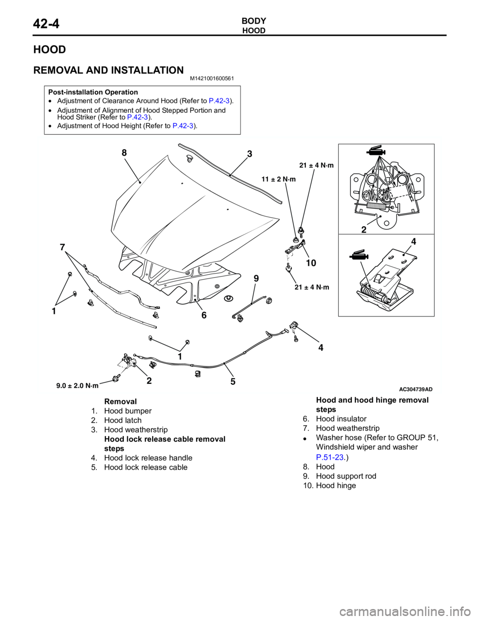
HOOD
BODY42-4
HOOD
REMOVAL AND INSTALLATIONM1421001600561
Post-installation Operation
•Adjustment of Clearance Around Hood (Refer to P.42-3).
•Adjustment of Alignment of Hood Stepped Portion and
Hood Striker (Refer to P.42-3).
•Adjustment of Hood Height (Refer to P.42-3).
AC304739
1 1
22
44
5 6 73 8
910
AD9.0 ± 2.0 N·m21 ± 4 N·m 11 ± 2 N·m21 ± 4 N·m
Removal
1. Hood bumper
2. Hood latch
3. Hood weatherstrip
Hood lock release cable removal
steps
4. Hood lock release handle
5. Hood lock release cableHood and hood hinge removal
steps
6. Hood insulator
7. Hood weatherstrip
•Washer hose (Refer to GROUP 51,
Windshield wiper and washer
P.51-23.)
8. Hood
9. Hood support rod
10. Hood hinge
Page 286 of 788
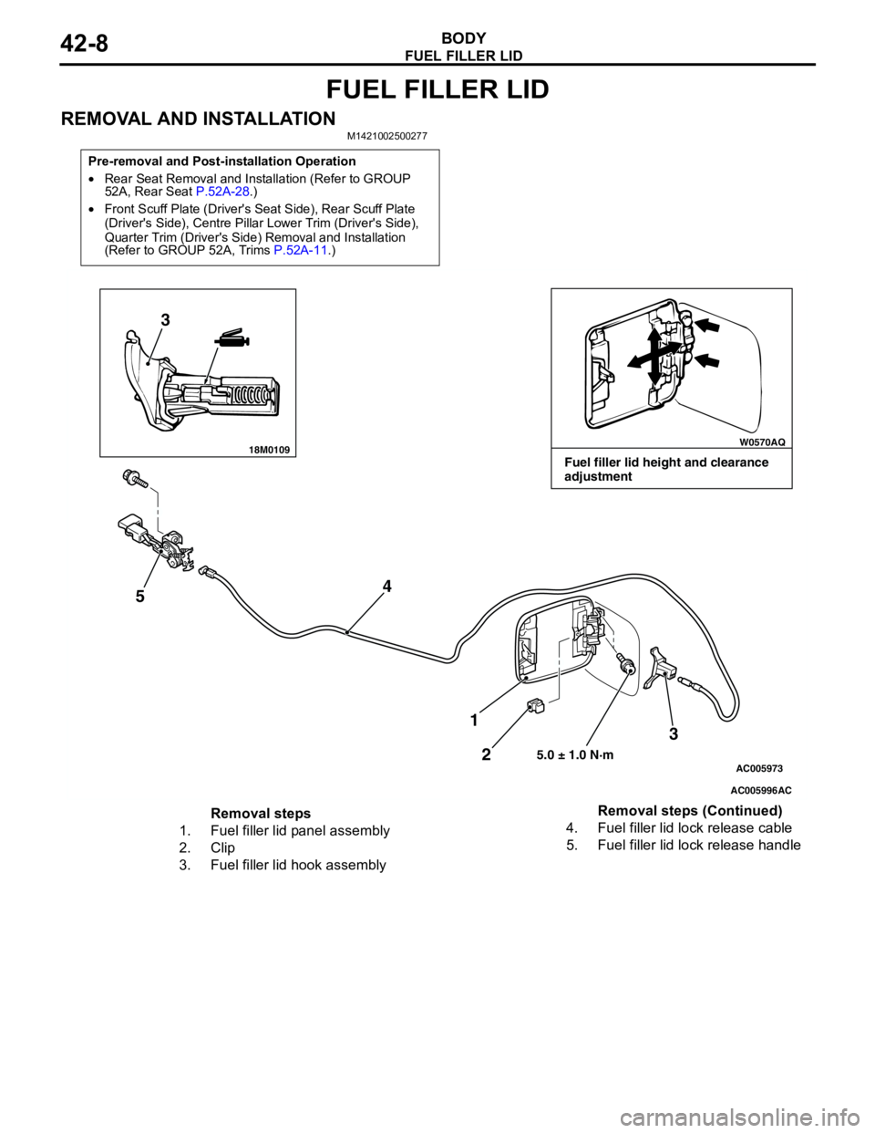
FUEL FILLER LID
BODY42-8
FUEL FILLER LID
REMOVAL AND INSTALLATIONM1421002500277
Pre-removal and Post-installation Operation
•Rear Seat Removal and Installation (Refer to GROUP
52A, Rear Seat P.52A-28.)
•Front Scuff Plate (Driver's Seat Side), Rear Scuff Plate
(Driver's Side), Centre Pillar Lower Trim (Driver's Side),
Quarter Trim (Driver's Side) Removal and Installation
(Refer to GROUP 52A, Trims P.52A-11.)
18M0109W0570AQ
AC005996
AC005973
3
54
3
2 1
5.0 ± 1.0 N·m
AC
Fuel filler lid height and clearance
adjustment
Removal steps
1. Fuel filler lid panel assembly
2. Clip
3. Fuel filler lid hook assembly4. Fuel filler lid lock release cable
5. Fuel filler lid lock release handleRemoval steps (Continued)