fog MITSUBISHI LANCER 2005 Workshop Manual
[x] Cancel search | Manufacturer: MITSUBISHI, Model Year: 2005, Model line: LANCER, Model: MITSUBISHI LANCER 2005Pages: 788, PDF Size: 45.98 MB
Page 341 of 788
FRONT BUMPER ASSEMBLY
EXTERIOR51-3
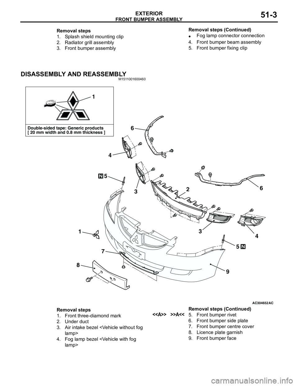
DISASSEMBLY AND REASSEMBLYM1511001600460
Removal steps
1. Splash shield mounting clip
2. Radiator grill assembly
3. Front bumper assembly•Fog lamp connector connection
4. Front bumper beam assembly
5. Front bumper fixing clip Removal steps (Continued)
AC304652AC
Double-sided tape: Generic products
[ 20 mm width and 0.8 mm thickness ]
1
1
8
7
9
6
6
5
5
3
4
34
N
N
2
Removal steps
1. Front three-diamond mark
2. Under duct
3. Air intake bezel
4. Fog lamp bezel
6. Front bumper side plate
7. Front bumper centre cover
8. Licence plate garnish
9. Front bumper face Removal steps (Continued)
Page 345 of 788
REAR BUMPER ASSEMBLY
EXTERIOR51-7
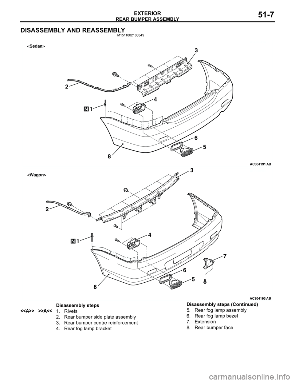
DISASSEMBLY AND REASSEMBLYM1511002100349
AC300414
AC304191
1
2
8
N
3
4
5
6
AB
AC300200
AC304193
1
2
8
N
3
4
5
7
6
AB
Disassembly steps
<> >>A<<1. Rivets
2. Rear bumper side plate assembly
3. Rear bumper centre reinforcement
4. Rear fog lamp bracket5. Rear fog lamp assembly
6. Rear fog lamp bezel
7. Extension
8. Rear bumper face Disassembly steps (Continued)
Page 374 of 788
DOOR MIRROR
EXTERIOR51-36
DOOR MIRROR
GENERAL INFORMATIONM1511000100536
DOOR MIRROR OPERATION
Remote Controlled Mirror Operation
•The mirror on the door mirror moves up/down
and left/right by operating the remote controlled
door mirror switch when the ignition switch is in
the "ON" or "ACC" position.Heated Door Mirror operation
•The defogger relay switch is activated (ON) by
turning on the A/C-ECU built-in defogger switch
when the ignition switch is in the "ON" position.
When the defogger relay is turned ON, power is
supplied to the defogger and door mirror, and the
heater of the door mirror (heated door mirror)
starts operations. The defogger comes with a
timer function and will automatically turn OFF the
switch approximately 11 minutes after the
defogger switch is turned ON. The heated door
mirror operations are also terminated along with
the defogger, at this time.
SERVICE SPECIFICATIONM1511000300347
SPECIAL TOOLM1511000601103
TROUBLESHOOTING
DIAGNOSIS TROUBLESHOOTING FLOWM1511014600169
Refer to GROUP 00 − How to Use
Troubleshooting/Inspection Service Points P.00-5.
TROUBLE SYMPTOM CHARTM1511015000160
ItemStandard value
Heated door mirror operation current Ω5.9 − 7.8
Tool Number Name Application
MB990784 Ornament remover Removal of remote controlled
mirror switch
MB990784
Symptom Inspection
procedureReference
page
All heated door mirrors do not operate 1
P.51-37
The right or left heated door mirror does not operate 2
P.51-39
Page 375 of 788
DOOR MIRROR
EXTERIOR51-37
SYMPTOM PROCEDURES
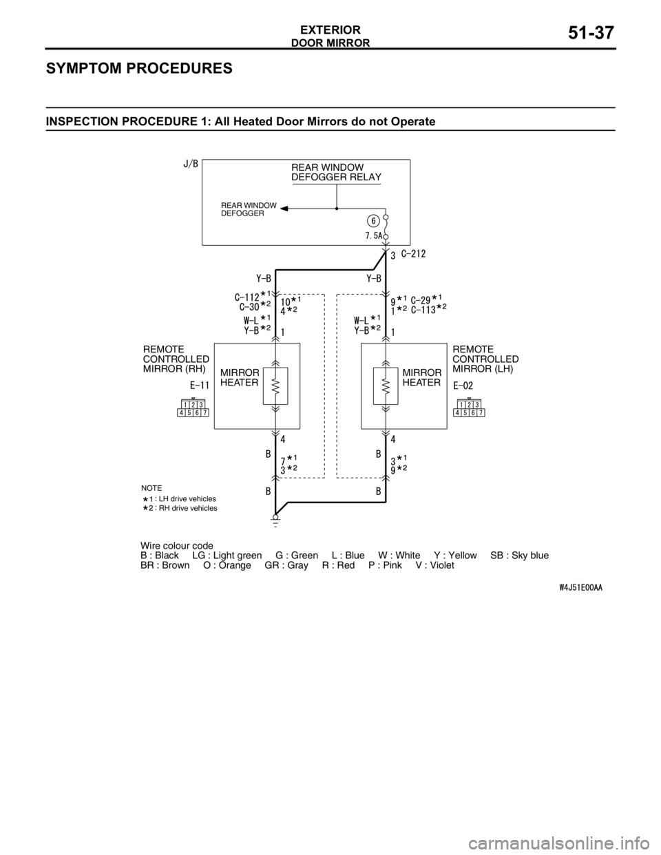
INSPECTION PROCEDURE 1: All Heated Door Mirrors do not Operate
Wire colour code
B : Black LG : Light green G : Green L : Blue W : White Y : Yellow SB : Sky blue
BR : Brown O : Orange GR : Gray R : Red P : Pink V : Violet REAR WINDOW
DEFOGGER RELAY
REAR WINDOW
DEFOGGER
REMOTE
CONTROLLED
MIRROR (LH) REMOTE
CONTROLLED
MIRROR (RH)
MIRROR
HEATERMIRROR
HEATER
NOTELH drive vehicles
RH drive vehicles
Page 376 of 788
DOOR MIRROR
EXTERIOR51-38
COMMENTS ON TROUBLE SYMPTOM
The heated door mirrors should works for
approximately 11 minutes when the rear defogger
switch is turned on. If the mirror heater does not work
for the specified period, the defogger relay circuit
(heated door mirror power supply circuit) may be
defective.
Possible causes
•Damaged harness wires and connectors
DIAGNOSIS PROCEDURE
STEP 1. Check the rear window defogger.
Check that the rear window defogger system should
work normally.
Q: Is the check result normal?
YES :
Go to Step 2.
NO : Troubleshoot the rear window defogger
(Refer to GROUP 55,
TroubleshootingP.55-42).
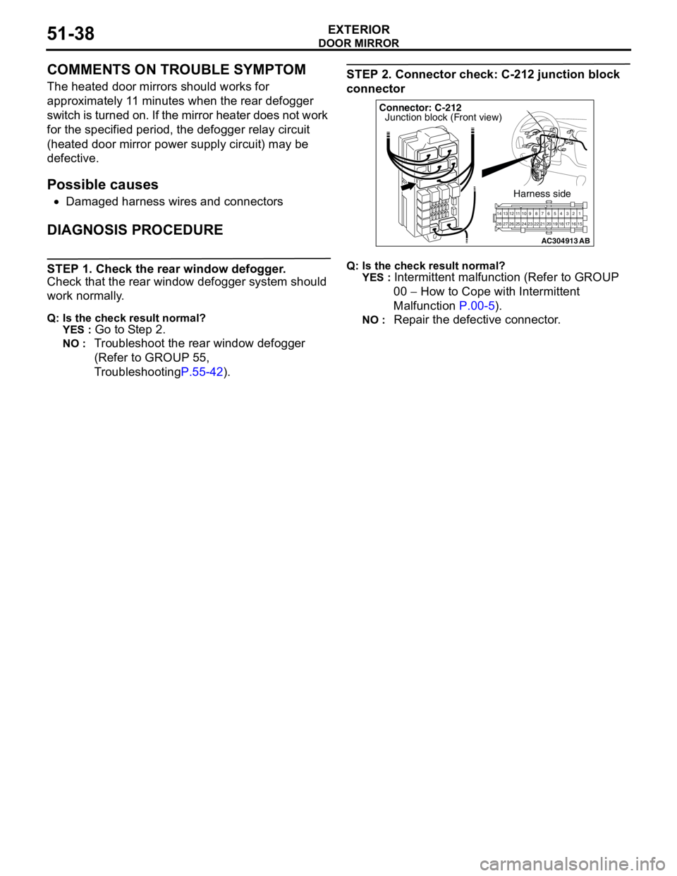
STEP 2. Connector check: C-212 junction block
connector
Q: Is the check result normal?
YES :
Intermittent malfunction (Refer to GROUP
00 − How to Cope with Intermittent
Malfunction P.00-5).
NO : Repair the defective connector.
AC304913
21716151718 201912345 623 222425282627981011141213
Connector: C-212
Harness side
AB
Junction block (Front view)
Page 377 of 788
DOOR MIRROR
EXTERIOR51-39
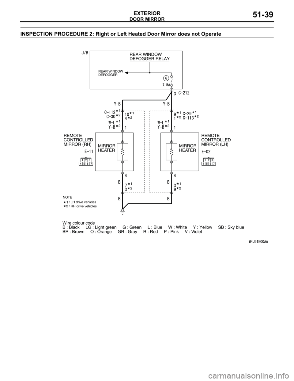
INSPECTION PROCEDURE 2: Right or Left Heated Door Mirror does not Operate
Wire colour code
B : Black LG : Light green G : Green L : Blue W : White Y : Yellow SB : Sky blue
BR : Brown O : Orange GR : Gray R : Red P : Pink V : Violet REAR WINDOW
DEFOGGER RELAY
REAR WINDOW
DEFOGGER
REMOTE
CONTROLLED
MIRROR (LH) REMOTE
CONTROLLED
MIRROR (RH)
MIRROR
HEATERMIRROR
HEATER
NOTELH drive vehicles
RH drive vehicles
Page 379 of 788
DOOR MIRROR
EXTERIOR51-41
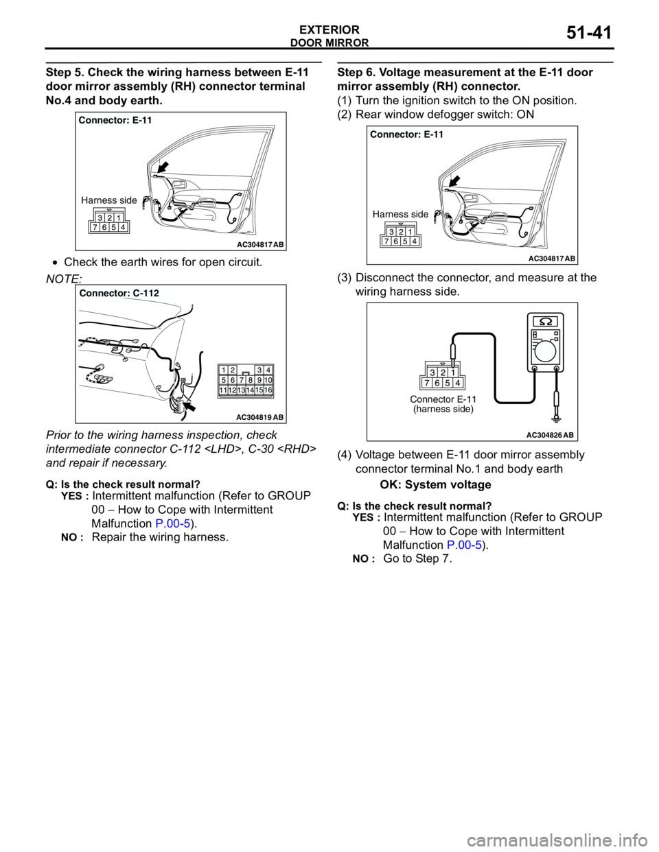
Step 5. Check the wiring harness between E-11
door mirror assembly (RH) connector terminal
No.4 and body earth.
•Check the earth wires for open circuit.
NOTE:
Prior to the wiring harness inspection, check
intermediate connector C-112
and repair if necessary.
Q: Is the check result normal?
YES :
Intermittent malfunction (Refer to GROUP
00 − How to Cope with Intermittent
Malfunction P.00-5).
NO : Repair the wiring harness.
Step 6. Voltage measurement at the E-11 door
mirror assembly (RH) connector.
(1) Turn the ignition switch to the ON position.
(2) Rear window defogger switch: ON
(3) Disconnect the connector, and measure at the
wiring harness side.
(4) Voltage between E-11 door mirror assembly
connector terminal No.1 and body earth
OK: System voltage
Q: Is the check result normal?
YES :
Intermittent malfunction (Refer to GROUP
00 − How to Cope with Intermittent
Malfunction P.00-5).
NO : Go to Step 7.
AC304817
Connector: E-11
Harness side
AB
AC304819
Connector: C-112
AB
AC304817
Connector: E-11
Harness side
AB
AC304826
Connector E-11
(harness side)
AB
Page 382 of 788
DOOR MIRROR
EXTERIOR51-44
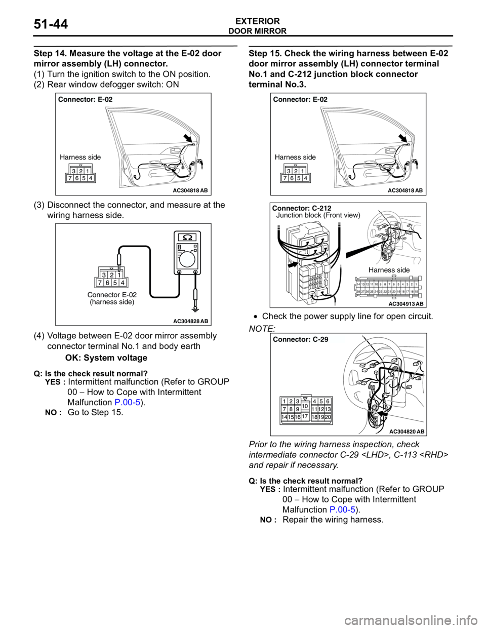
Step 14. Measure the voltage at the E-02 door
mirror assembly (LH) connector.
(1) Turn the ignition switch to the ON position.
(2) Rear window defogger switch: ON
(3) Disconnect the connector, and measure at the
wiring harness side.
(4) Voltage between E-02 door mirror assembly
connector terminal No.1 and body earth
OK: System voltage
Q: Is the check result normal?
YES :
Intermittent malfunction (Refer to GROUP
00 − How to Cope with Intermittent
Malfunction P.00-5).
NO : Go to Step 15.
Step 15. Check the wiring harness between E-02
door mirror assembly (LH) connector terminal
No.1 and C-212 junction block connector
terminal No.3.
•Check the power supply line for open circuit.
NOTE:
Prior to the wiring harness inspection, check
intermediate connector C-29
and repair if necessary.
Q: Is the check result normal?
YES :
Intermittent malfunction (Refer to GROUP
00 − How to Cope with Intermittent
Malfunction P.00-5).
NO : Repair the wiring harness.
AC304818
Connector: E-02
Harness side
AB
AC304828
Connector E-02
(harness side)
AB
AC304818
Connector: E-02
Harness side
AB
AC304913
21716151718 201912345 623 222425282627981011141213
Connector: C-212
Harness side
AB
Junction block (Front view)
AC304820
Connector: C-29
AB
Page 390 of 788
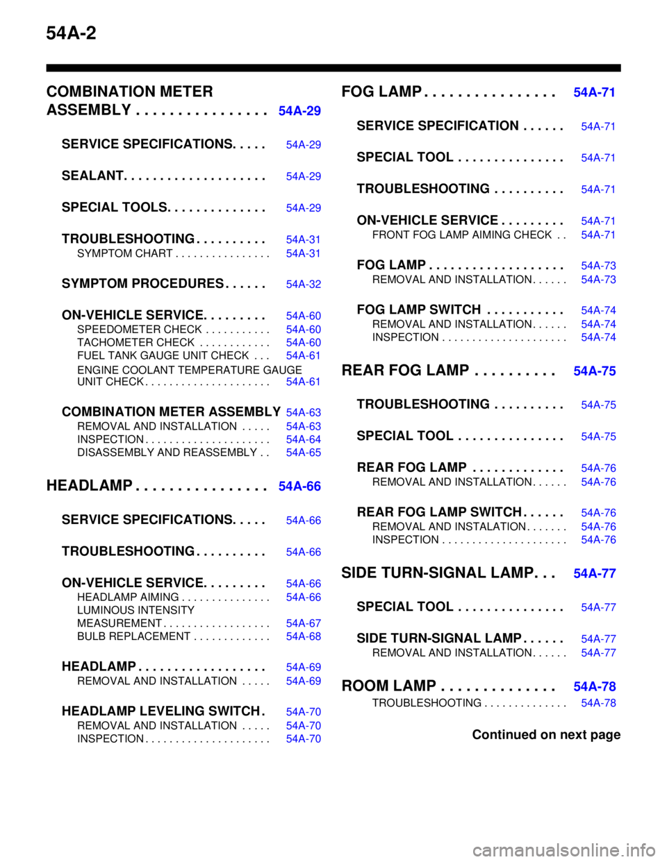
54A-2
COMBINATION METER
ASSEMBLY . . . . . . . . . . . . . . . .
54A-29
SERVICE SPECIFICATIONS. . . . .
54A-29
SEALANT. . . . . . . . . . . . . . . . . . . .54A-29
SPECIAL TOOLS. . . . . . . . . . . . . .54A-29
TROUBLESHOOTING . . . . . . . . . .54A-31
SYMPTOM CHART . . . . . . . . . . . . . . . . 54A-31
SYMPTOM PROCEDURES . . . . . .54A-32
ON-VEHICLE SERVICE. . . . . . . . .54A-60
SPEEDOMETER CHECK . . . . . . . . . . . 54A-60
TACHOMETER CHECK . . . . . . . . . . . . 54A-60
FUEL TANK GAUGE UNIT CHECK . . . 54A-61
ENGINE COOLANT TEMPERATURE GAUGE
UNIT CHECK . . . . . . . . . . . . . . . . . . . . . 54A-61
COMBINATION METER ASSEMBLY54A-63
REMOVAL AND INSTALLATION . . . . . 54A-63
INSPECTION . . . . . . . . . . . . . . . . . . . . . 54A-64
DISASSEMBLY AND REASSEMBLY . . 54A-65
HEADLAMP . . . . . . . . . . . . . . . .54A-66
SERVICE SPECIFICATIONS. . . . .
54A-66
TROUBLESHOOTING . . . . . . . . . .54A-66
ON-VEHICLE SERVICE. . . . . . . . .54A-66
HEADLAMP AIMING . . . . . . . . . . . . . . . 54A-66
LUMINOUS INTENSITY
MEASUREMENT . . . . . . . . . . . . . . . . . . 54A-67
BULB REPLACEMENT . . . . . . . . . . . . . 54A-68
HEADLAMP . . . . . . . . . . . . . . . . . .54A-69
REMOVAL AND INSTALLATION . . . . . 54A-69
HEADLAMP LEVELING SWITCH .54A-70
REMOVAL AND INSTALLATION . . . . . 54A-70
INSPECTION . . . . . . . . . . . . . . . . . . . . . 54A-70
FOG LAMP . . . . . . . . . . . . . . . . 54A-71
SERVICE SPECIFICATION . . . . . .
54A-71
SPECIAL TOOL . . . . . . . . . . . . . . .54A-71
TROUBLESHOOTING . . . . . . . . . .54A-71
ON-VEHICLE SERVICE . . . . . . . . .54A-71
FRONT FOG LAMP AIMING CHECK . . 54A-71
FOG LAMP . . . . . . . . . . . . . . . . . . .54A-73
REMOVAL AND INSTALLATION . . . . . . 54A-73
FOG LAMP SWITCH . . . . . . . . . . .54A-74
REMOVAL AND INSTALLATION . . . . . . 54A-74
INSPECTION . . . . . . . . . . . . . . . . . . . . . 54A-74
REAR FOG LAMP . . . . . . . . . . 54A-75
TROUBLESHOOTING . . . . . . . . . .
54A-75
SPECIAL TOOL . . . . . . . . . . . . . . .54A-75
REAR FOG LAMP . . . . . . . . . . . . .54A-76
REMOVAL AND INSTALLATION . . . . . . 54A-76
REAR FOG LAMP SWITCH . . . . . .54A-76
REMOVAL AND INSTALATION . . . . . . . 54A-76
INSPECTION . . . . . . . . . . . . . . . . . . . . . 54A-76
SIDE TURN-SIGNAL LAMP. . . 54A-77
SPECIAL TOOL . . . . . . . . . . . . . . .
54A-77
SIDE TURN-SIGNAL LAMP . . . . . .54A-77
REMOVAL AND INSTALLATION . . . . . . 54A-77
ROOM LAMP . . . . . . . . . . . . . . 54A-78
TROUBLESHOOTING . . . . . . . . . . . . . . 54A-78
Continued on next page
Page 391 of 788
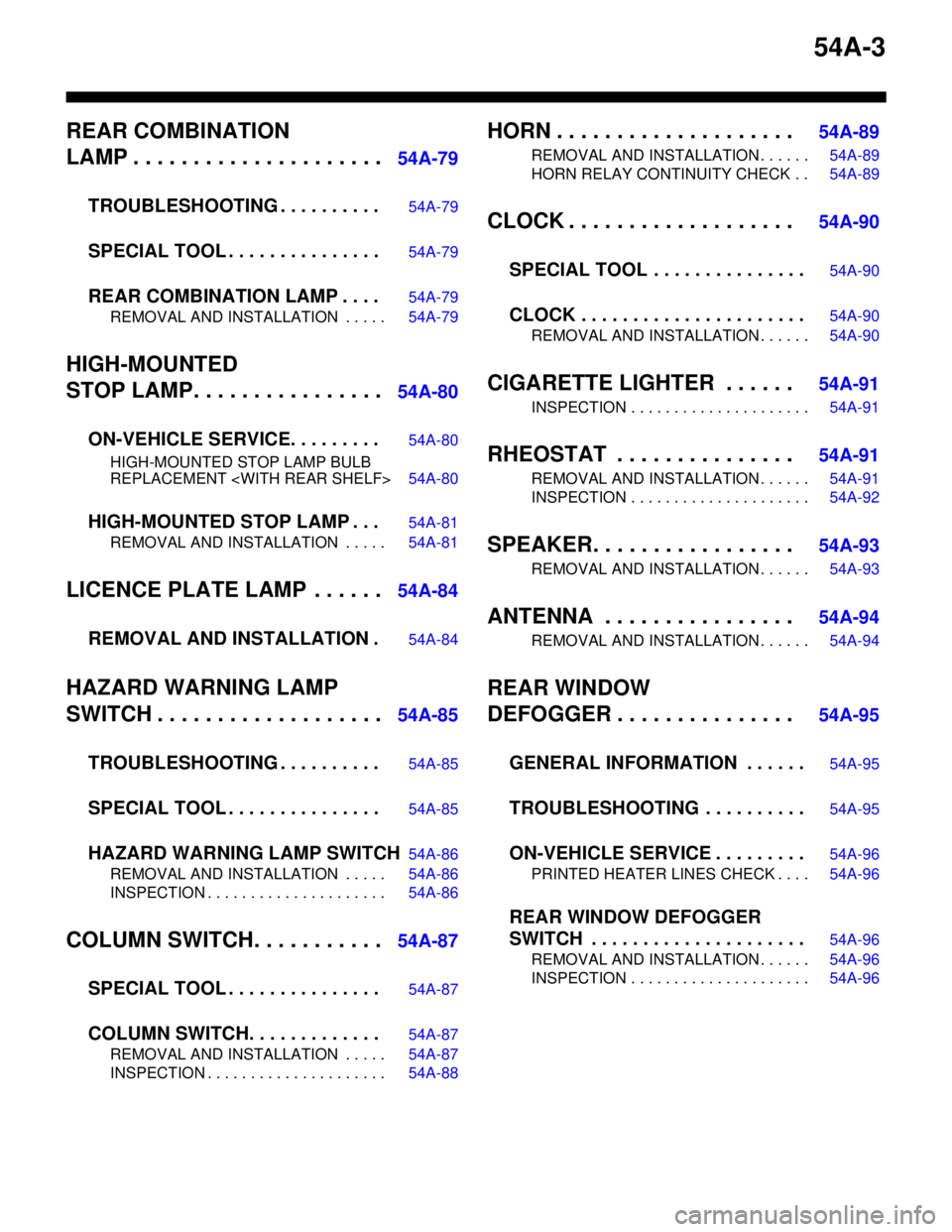
54A-3
REAR COMBINATION
LAMP . . . . . . . . . . . . . . . . . . . . .
54A-79
TROUBLESHOOTING . . . . . . . . . .
54A-79
SPECIAL TOOL . . . . . . . . . . . . . . .54A-79
REAR COMBINATION LAMP . . . .54A-79
REMOVAL AND INSTALLATION . . . . . 54A-79
HIGH-MOUNTED
STOP LAMP. . . . . . . . . . . . . . . .
54A-80
ON-VEHICLE SERVICE. . . . . . . . .
54A-80
HIGH-MOUNTED STOP LAMP BULB
REPLACEMENT
HIGH-MOUNTED STOP LAMP . . .54A-81
REMOVAL AND INSTALLATION . . . . . 54A-81
LICENCE PLATE LAMP . . . . . .54A-84
REMOVAL AND INSTALLATION .
54A-84
HAZARD WARNING LAMP
SWITCH . . . . . . . . . . . . . . . . . . .
54A-85
TROUBLESHOOTING . . . . . . . . . .
54A-85
SPECIAL TOOL . . . . . . . . . . . . . . .54A-85
HAZARD WARNING LAMP SWITCH54A-86
REMOVAL AND INSTALLATION . . . . . 54A-86
INSPECTION . . . . . . . . . . . . . . . . . . . . . 54A-86
COLUMN SWITCH. . . . . . . . . . .54A-87
SPECIAL TOOL . . . . . . . . . . . . . . .
54A-87
COLUMN SWITCH. . . . . . . . . . . . .54A-87
REMOVAL AND INSTALLATION . . . . . 54A-87
INSPECTION . . . . . . . . . . . . . . . . . . . . . 54A-88
HORN . . . . . . . . . . . . . . . . . . . . 54A-89
REMOVAL AND INSTALLATION . . . . . . 54A-89
HORN RELAY CONTINUITY CHECK . . 54A-89
CLOCK . . . . . . . . . . . . . . . . . . . 54A-90
SPECIAL TOOL . . . . . . . . . . . . . . .
54A-90
CLOCK . . . . . . . . . . . . . . . . . . . . . .54A-90
REMOVAL AND INSTALLATION . . . . . . 54A-90
CIGARETTE LIGHTER . . . . . . 54A-91
INSPECTION . . . . . . . . . . . . . . . . . . . . . 54A-91
RHEOSTAT . . . . . . . . . . . . . . . 54A-91
REMOVAL AND INSTALLATION . . . . . . 54A-91
INSPECTION . . . . . . . . . . . . . . . . . . . . . 54A-92
SPEAKER. . . . . . . . . . . . . . . . . 54A-93
REMOVAL AND INSTALLATION . . . . . . 54A-93
ANTENNA . . . . . . . . . . . . . . . . 54A-94
REMOVAL AND INSTALLATION . . . . . . 54A-94
REAR WINDOW
DEFOGGER . . . . . . . . . . . . . . .
54A-95
GENERAL INFORMATION . . . . . .
54A-95
TROUBLESHOOTING . . . . . . . . . .54A-95
ON-VEHICLE SERVICE . . . . . . . . .54A-96
PRINTED HEATER LINES CHECK . . . . 54A-96
REAR WINDOW DEFOGGER
SWITCH . . . . . . . . . . . . . . . . . . . . .
54A-96
REMOVAL AND INSTALLATION . . . . . . 54A-96
INSPECTION . . . . . . . . . . . . . . . . . . . . . 54A-96