ignition switch trouble shooting MITSUBISHI LANCER 2005 Workshop Manual
[x] Cancel search | Manufacturer: MITSUBISHI, Model Year: 2005, Model line: LANCER, Model: MITSUBISHI LANCER 2005Pages: 788, PDF Size: 45.98 MB
Page 21 of 788
TROUBLESHOOTING
ENGINE COOLING14-7
CIRCUIT OPERATION
•The cooling fan motor drive control unit is
powered from fusible link (2).
•The engine-ECU
uses input signals from the A/C switch, the
water temperature sensor unit and the vehicle
speed sensor
sensor to control the speed of the cooling
fan motor (L.H.) and the cooling fan motor (R.H.)
<4G1 (Vehicles with A/C)> or A/C condenser fan
motor <4G6>.
•The engine-ECU
controls the cooling fan motor drive control
unit to activate the cooling fan motor (L.H.) and
the cooling fan motor (R.H.) <4G1 (Vehicles with
A/C)> or A/C condenser fan motor <4G6>.
TECHNICAL DESCRIPTION
•The cause could be a malfunction of the cooling
fan motor drive control unit power supply or earth
circuit.
•If the communication line wiring harness between
the cooling fan motor drive control unit and the
engine-ECU
short-circuited to earth, the cooling fan motor
(L.H.) and the cooling fan motor (R.H.) <4G1
(Vehicles with A/C)> or the A/C condenser fan
motor <4G6> will not rotate.
•The cause could also be a malfunction of the
cooling fan motor (L.H.).
•The cause could also be a malfunction of imput
signal from the A/C switch, the water temperature
sensor unit and the vehicle speed sensor
or the output shaft speed sensor to the
engine-ECU
•The cause could also be a malfunction of the
cooling fan motor drive control unit or the
engine-ECU
TROUBLESHOOTING HINTS
•Malfunction of fusible link (2)
•Malfunction of fan control relay
•Malfunction of cooling fan motor (L.H.)
•Malfunction of cooling fan motor drive control unit
•Malfunction of engine-ECU
engine-A/T-ECU
•Damaged wiring harness or connector
DIAGNOSIS
STEP 1. Check the cooling fan motor (L.H.).
Refer to P.14-25.
Q: Is the cooling fan motor (L.H.) in good condition?
YES :
Go to Step 2 .
NO : Replace the cooling fan motor (L.H.) (Refer
to P.14-35). Then go to Step 24 .
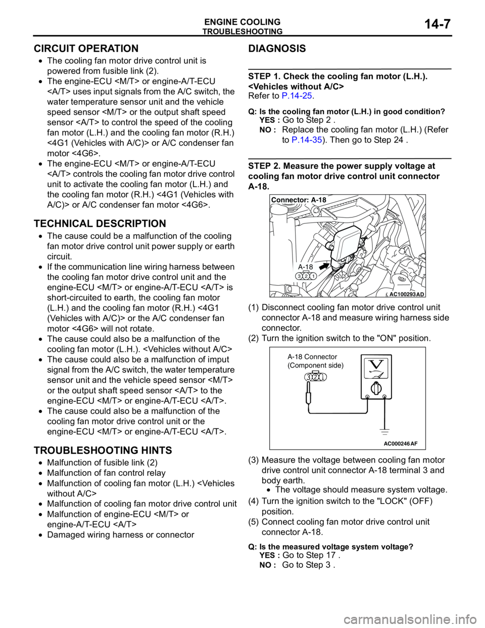
STEP 2. Measure the power supply voltage at
cooling fan motor drive control unit connector
A-18.
(1) Disconnect cooling fan motor drive control unit
connector A-18 and measure wiring harness side
connector.
(2) Turn the ignition switch to the "ON" position.
(3) Measure the voltage between cooling fan motor
drive control unit connector A-18 terminal 3 and
body earth.
•The voltage should measure system voltage.
(4) Turn the ignition switch to the "LOCK" (OFF)
position.
(5) Connect cooling fan motor drive control unit
connector A-18.
Q: Is the measured voltage system voltage?
YES :
Go to Step 17 .
NO : Go to Step 3 .
AC100293
A-18
321
Connector: A-18
AD
AC000246AF
A-18 Connector
(Component side)
Page 22 of 788
TROUBLESHOOTING
ENGINE COOLING14-8
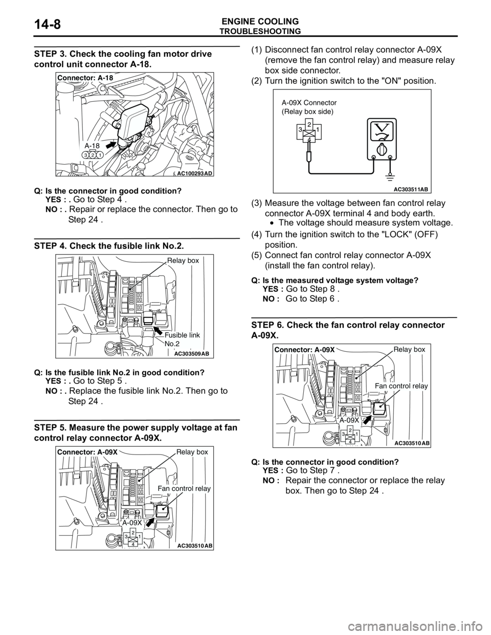
STEP 3. Check the cooling fan motor drive
control unit connector A-18.
Q: Is the connector in good condition?
YES : .
Go to Step 4 .
NO : . Repair or replace the connector. Then go to
Step 24 .
STEP 4. Check the fusible link No.2.
Q: Is the fusible link No.2 in good condition?
YES : .
Go to Step 5 .
NO : . Replace the fusible link No.2. Then go to
Step 24 .
STEP 5. Measure the power supply voltage at fan
control relay connector A-09X.(1) Disconnect fan control relay connector A-09X
(remove the fan control relay) and measure relay
box side connector.
(2) Turn the ignition switch to the "ON" position.
(3) Measure the voltage between fan control relay
connector A-09X terminal 4 and body earth.
•The voltage should measure system voltage.
(4) Turn the ignition switch to the "LOCK" (OFF)
position.
(5) Connect fan control relay connector A-09X
(install the fan control relay).
Q: Is the measured voltage system voltage?
YES :
Go to Step 8 .
NO : Go to Step 6 .
STEP 6. Check the fan control relay connector
A-09X.
Q: Is the connector in good condition?
YES :
Go to Step 7 .
NO : Repair the connector or replace the relay
box. Then go to Step 24 .
AC100293
A-18
321
Connector: A-18
AD
AC303509AB
Fusible link
No.2
Relay box
AC303510AB
Fan control relay
Relay boxConnector: A-09X
A-09X
AC303511AB
A-09X Connector
(Relay box side)
AC303510AB
Fan control relay
Relay boxConnector: A-09X
A-09X
Page 23 of 788
TROUBLESHOOTING
ENGINE COOLING14-9
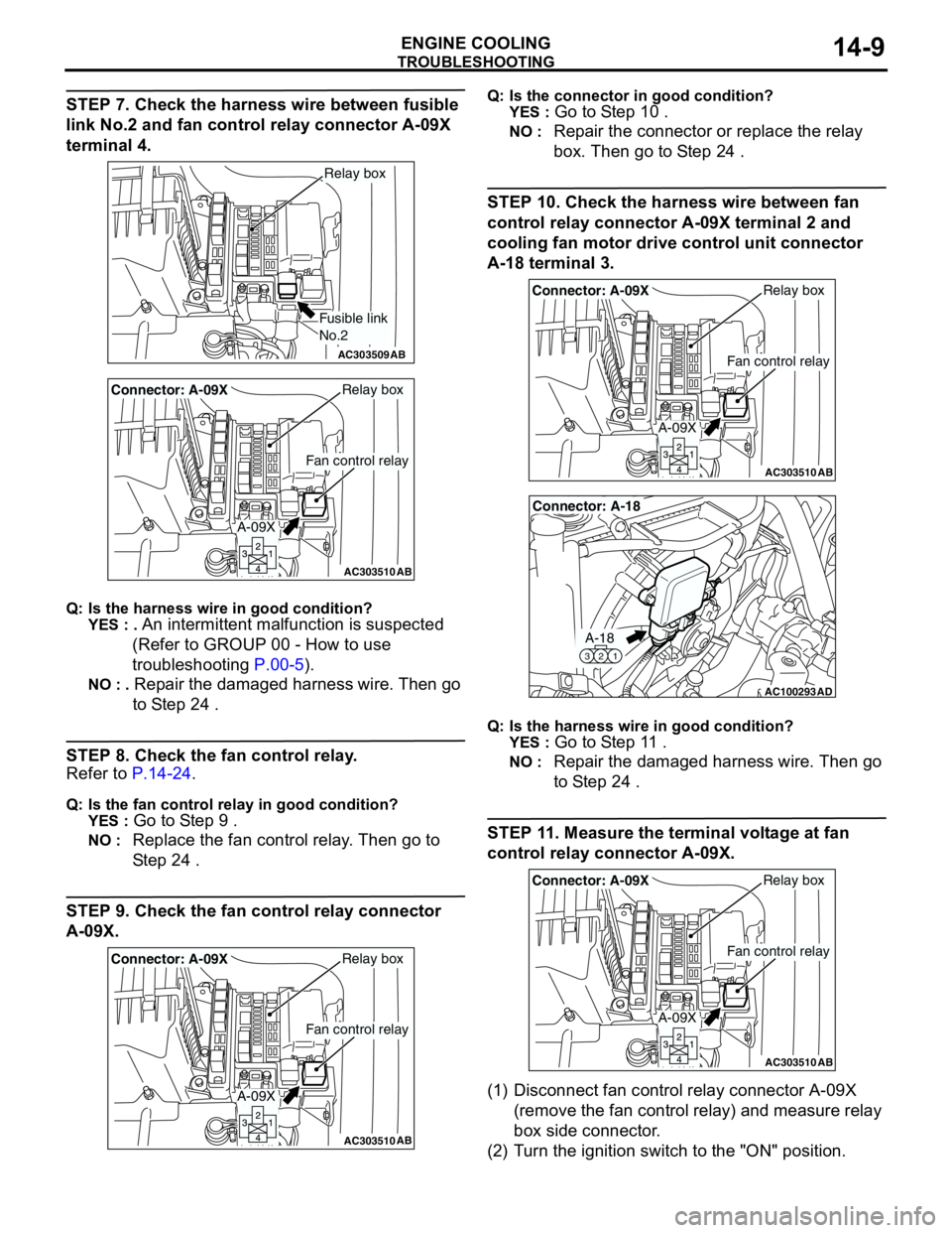
STEP 7. Check the harness wire between fusible
link No.2 and fan control relay connector A-09X
terminal 4.
Q: Is the harness wire in good condition?
YES : .
An intermittent malfunction is suspected
(Refer to GROUP 00 - How to use
troubleshooting P.00-5).
NO : . Repair the damaged harness wire. Then go
to Step 24 .
STEP 8. Check the fan control relay.
Refer to P.14-24.
Q: Is the fan control relay in good condition?
YES :
Go to Step 9 .
NO : Replace the fan control relay. Then go to
Step 24 .
STEP 9. Check the fan control relay connector
A-09X.
Q: Is the connector in good condition?
YES :
Go to Step 10 .
NO : Repair the connector or replace the relay
box. Then go to Step 24 .
STEP 10. Check the harness wire between fan
control relay connector A-09X terminal 2 and
cooling fan motor drive control unit connector
A-18 terminal 3.
Q: Is the harness wire in good condition?
YES :
Go to Step 11 .
NO : Repair the damaged harness wire. Then go
to Step 24 .
STEP 11. Measure the terminal voltage at fan
control relay connector A-09X.
(1) Disconnect fan control relay connector A-09X
(remove the fan control relay) and measure relay
box side connector.
(2) Turn the ignition switch to the "ON" position.
AC303509AB
Fusible link
No.2
Relay box
AC303510AB
Fan control relay
Relay boxConnector: A-09X
A-09X
AC303510AB
Fan control relay
Relay boxConnector: A-09X
A-09X
AC303510AB
Fan control relay
Relay boxConnector: A-09X
A-09X
AC100293
A-18
321
Connector: A-18
AD
AC303510AB
Fan control relay
Relay boxConnector: A-09X
A-09X
Page 24 of 788
TROUBLESHOOTING
ENGINE COOLING14-10
(3) Measure the voltage between fan control relay
connector A-09X terminal 1 and body earth.
•The voltage should measure system voltage.
(4) Turn the ignition switch to the "LOCK" (OFF)
position.
(5) Connect fan control relay connector A-09X
(install the fan control relay).
Q: Is the measured voltage system voltage?
YES : .
Go to Step 14 .
NO : . Go to Step 12 .
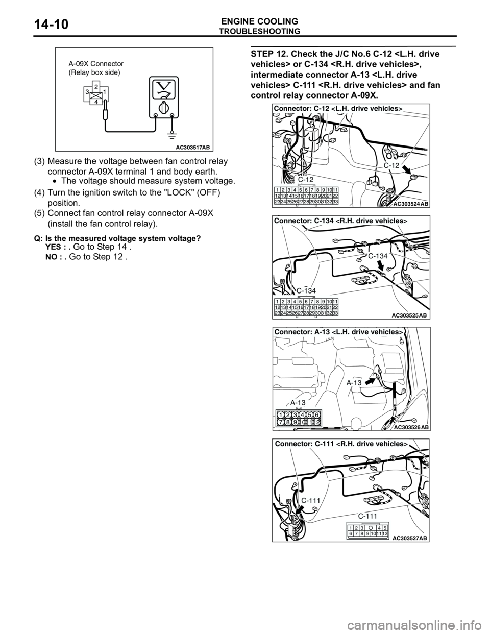
STEP 12. Check the J/C No.6 C-12
intermediate connector A-13
control relay connector A-09X.
AC303517AB
A-09X Connector
(Relay box side)
AC303524
Connector: C-12
AB
C-12
C-12
AC303525
Connector: C-134
AB
C-134
C-134
AC303526
Connector: A-13
AB
A-13
A-13
AC303527
Connector: C-111
AB
C-111
C-111
615
121179
810234
Page 29 of 788
TROUBLESHOOTING
ENGINE COOLING14-15
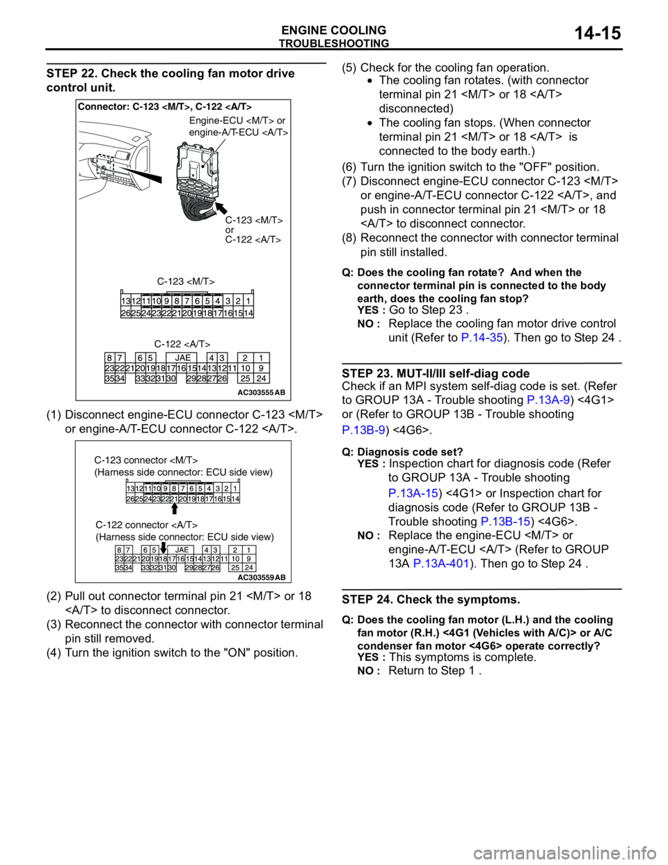
STEP 22. Check the cooling fan motor drive
control unit.
(1) Disconnect engine-ECU connector C-123
or engine-A/T-ECU connector C-122 .
(2) Pull out connector terminal pin 21
to disconnect connector.
(3) Reconnect the connector with connector terminal
pin still removed.
(4) Turn the ignition switch to the "ON" position.(5) Check for the cooling fan operation.
•The cooling fan rotates. (with connector
terminal pin 21
disconnected)
•The cooling fan stops. (When connector
terminal pin 21
connected to the body earth.)
(6) Turn the ignition switch to the "OFF" position.
(7) Disconnect engine-ECU connector C-123
or engine-A/T-ECU connector C-122 , and
push in connector terminal pin 21
to disconnect connector.
(8) Reconnect the connector with connector terminal
pin still installed.
Q: Does the cooling fan rotate? And when the
connector terminal pin is connected to the body
earth, does the cooling fan stop?
YES :
Go to Step 23 .
NO : Replace the cooling fan motor drive control
unit (Refer to P.14-35). Then go to Step 24 .
STEP 23. MUT-II/III self-diag code
Check if an MPI system self-diag code is set. (Refer
to GROUP 13A - Trouble shooting P.13A-9) <4G1>
or (Refer to GROUP 13B - Trouble shooting
P.13B-9) <4G6>.
Q: Diagnosis code set?
YES :
Inspection chart for diagnosis code (Refer
to GROUP 13A - Trouble shooting
P.13A-15) <4G1> or Inspection chart for
diagnosis code (Refer to GROUP 13B -
Trouble shooting P.13B-15) <4G6>.
NO : Replace the engine-ECU
engine-A/T-ECU (Refer to GROUP
13A P.13A-401). Then go to Step 24 .
STEP 24. Check the symptoms.
Q: Does the cooling fan motor (L.H.) and the cooling
fan motor (R.H.) <4G1 (Vehicles with A/C)> or A/C
condenser fan motor <4G6> operate correctly?
YES :
This symptoms is complete.
NO : Return to Step 1 .
AC303555AB
Connector: C-123
C-123
or
C-122
C-123
Engine-ECU
engine-A/T-ECU
C-122
AC303559
C-122 connector
(Harness side connector: ECU side view)
AB
C-123 connector
(Harness side connector: ECU side view)
Page 33 of 788
TROUBLESHOOTING
ENGINE COOLING14-19
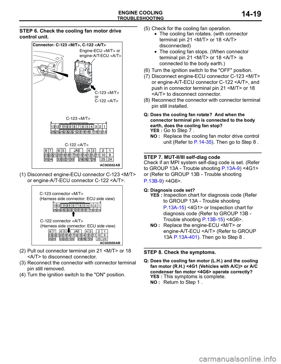
STEP 6. Check the cooling fan motor drive
control unit.
(1) Disconnect engine-ECU connector C-123
or engine-A/T-ECU connector C-122 .
(2) Pull out connector terminal pin 21
to disconnect connector.
(3) Reconnect the connector with connector terminal
pin still removed.
(4) Turn the ignition switch to the "ON" position.(5) Check for the cooling fan operation.
•The cooling fan rotates. (with connector
terminal pin 21
disconnected)
•The cooling fan stops. (When connector
terminal pin 21
connected to the body earth.)
(6) Turn the ignition switch to the "OFF" position.
(7) Disconnect engine-ECU connector C-123
or engine-A/T-ECU connector C-122 , and
push in connector terminal pin 21
to disconnect connector.
(8) Reconnect the connector with connector terminal
pin still installed.
Q: Does the cooling fan rotate? And when the
connector terminal pin is connected to the body
earth, does the cooling fan stop?
YES :
Go to Step 7 .
NO : Replace the cooling fan motor drive control
unit (Refer to P.14-35). Then go to Step 8 .
STEP 7. MUT-II/III self-diag code
Check if an MPI system self-diag code is set. (Refer
to GROUP 13A - Trouble shooting P.13A-9) <4G1>
or (Refer to GROUP 13B - Trouble shooting
P.13B-9) <4G6>.
Q: Diagnosis code set?
YES :
Inspection chart for diagnosis code (Refer
to GROUP 13A - Trouble shooting
P.13A-15) <4G1> or Inspection chart for
diagnosis code (Refer to GROUP 13B -
Trouble shooting P.13B-15) <4G6>.
NO : Replace the engine-ECU
engine-A/T-ECU (Refer to GROUP
13A P.13A-401). Then go to Step 8 .
STEP 8. Check the symptoms.
Q: Does the cooling fan motor (L.H.) and the cooling
fan motor (R.H.) <4G1 (Vehicles with A/C)> or A/C
condenser fan motor <4G6> operate correctly?
YES :
This symptoms is complete.
NO : Return to Step 1 .
AC303555AB
Connector: C-123
C-123
or
C-122
C-123
Engine-ECU
engine-A/T-ECU
C-122
AC303559
C-122 connector
(Harness side connector: ECU side view)
AB
C-123 connector
(Harness side connector: ECU side view)
Page 331 of 788
KEYLESS ENTRY SYSTEM
BODY42-53
TROUBLESHOOTINGM1428000700287
The keyless entry system is controlled by the Smart
Wiring System (SWS). For troubleshooting, refer to
GROUP 54B, Troubleshooting P.54B-17 or GROUP
54C, Troubleshooting P.54C-4.
ON-VEHICLE SERVICE
KEYLESS ENTRY SYSTEM CHECKM1428001400096
Check the system as described below. If the system
does not work, carry out troubleshooting. Refer to
GROUP 54B, Troubleshooting P.54B-17, refer to
GROUP 54C, Troubleshooting P.54C-4.
•Operate the transmitter to check that the doors
and tailgate can be locked and unlocked.
•Operate the transmitter to check that the
answerback function works in response to door
and tailgate
NOTE: The adjustment function allows you to
change the answerback setting as follows. Prior
to that check, confirm which setting is activated.
.
•The hazard warning lamps flash twice when
locked and once when unlocked. The room
lamp flashes twice when locked and
illuminates for 15 seconds when unlocked.
•The hazard warning lamps do not flash when
locked and flash once when unlocked. The
room lamp flashes twice when locked and
illuminates for 15 seconds when unlocked.
•The hazard warning lamps flash twice when
locked and do not flash when unlocked. The
room lamp flashes twice when locked and
illuminates for 15 seconds when unlocked.
•The hazard warning lamps do not flash when
both locked and unlocked. The room lamp
flashes twice when locked and illuminates for
15 seconds when unlocked.
KEYLESS ENTRY SYSTEM TIMER LOCK
FUNCTION INSPECTION
M1428004000138
Push the transmitter unlock button and check to see
that the doors and tailgate
seconds. If it doesn't, then execute troubleshooting
remedies. Refer to GROUP 54B, Troubleshooting
P.54B-17, refer to GROUP 54C, Troubleshooting
P.54C-4.
ENABLING/DISABLING THE
ANSWERBACK FUNCTION
M1428003200214
If the keyless entry system locks or unlocks the
doors, the room lamp flashes or illuminates, the
hazard warning lamp flashes (hazard answerback
function). The hazard answerback function can be
enabled or disabled according to the following
procedure:
ENABLING/DISABLING THE HAZARD
ANSWERBACK FUNCTION
The hazard answerback function can be enabled or
disabled by one of the two following procedures.
1. Enter the hazard answerback customize mode by
performing one of the following steps. If the
ETACS-ECU enters the customize mode, its
buzzer will sound once.
(1) Turn the ignition switch to “LOCK”(OFF)
position.
(2) Turn off the hazard warning lamp switch.
CAUTION
Before connecting or disconnecting the earth,
turn the ignition switch to the "LOCK" (OFF)
position.
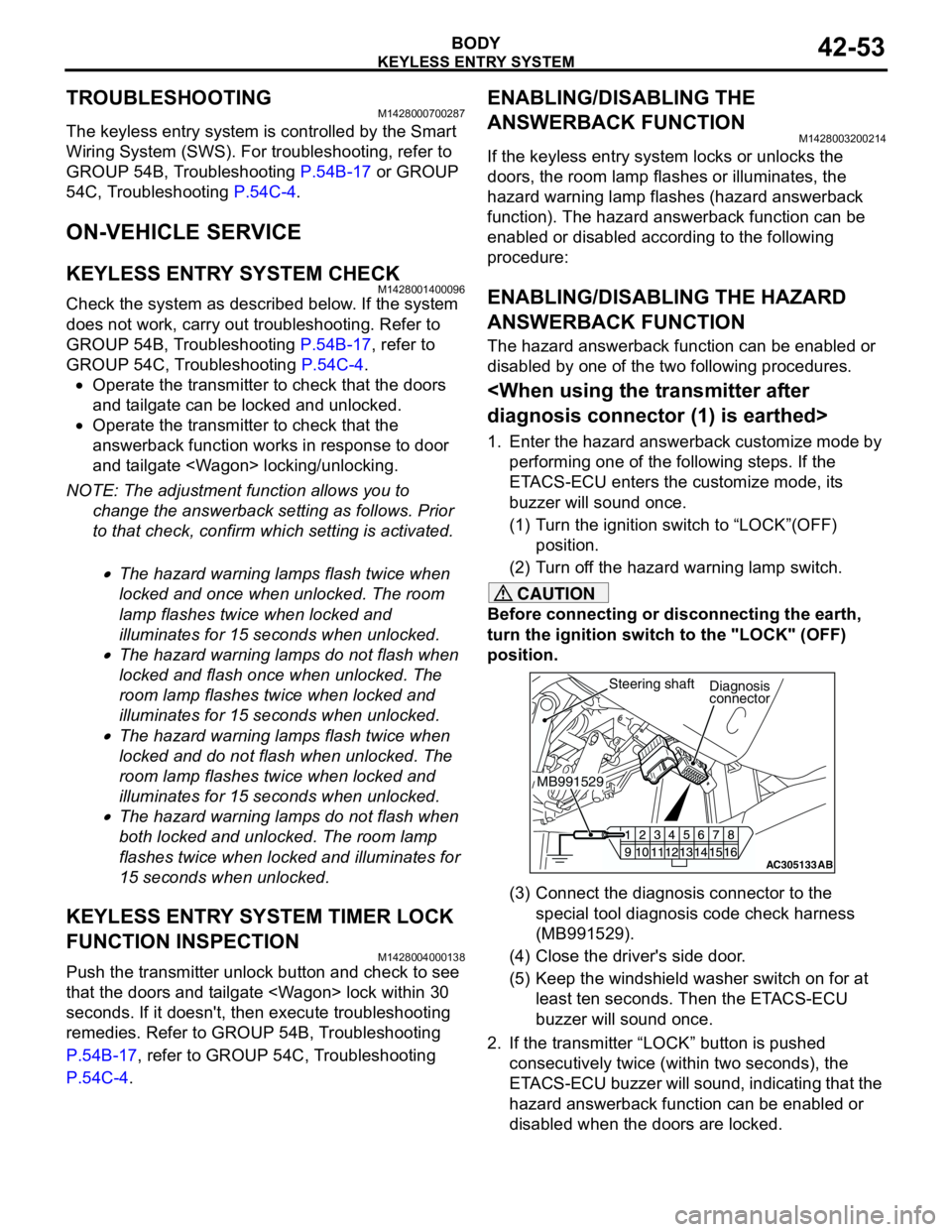
(3) Connect the diagnosis connector to the
special tool diagnosis code check harness
(MB991529).
(4) Close the driver's side door.
(5) Keep the windshield washer switch on for at
least ten seconds. Then the ETACS-ECU
buzzer will sound once.
2. If the transmitter “LOCK” button is pushed
consecutively twice (within two seconds), the
ETACS-ECU buzzer will sound, indicating that the
hazard answerback function can be enabled or
disabled when the doors are locked.
AC305133AB
Diagnosis
connector
MB991529Steering shaft
Page 360 of 788
WINDSHIELD WIPER AND WASHER
EXTERIOR51-22
SERVICE SPECIFICATIONM1511000300325
TROUBLESHOOTINGM1511000700323
The windshield wiper and washer are controlled by
the Smart Wiring System (SWS). For
troubleshooting, refer to GROUP 54B,
Troubleshooting P.54B-17 or GROUP 54C,
Troubleshooting P.54C-4.
NOTE: Even when the ETACS-ECU has failed, the
windshield wiper can work at low speed as fail-safe
mode. (Normally, the windshield wiper operates
when the ignition switch is at the "ACC" position. But,
if it enters the fail-safe mode, the wiper can operate
only when the ignition switch is at the "ON" position.)
ON-VEHICLE SERVICEM1511000800461
WINDSHIELD INTERMITTENT WIPER
INSPECTION
1. If the windshield intermittent wiper interval
adjusting knob is operated, the wiper interval
should change.
2. Holding the windshield intermittent wiper interval
adjusting knob, input the simulated vehicle speed
with MUT-II MB991502 and check that the wiper
interval changes as the vehicle speed changes.
3. If not, carry out the troubleshooting (Refer to
GROUP 54B, Troubleshooting P.54B-17 or
GROUP 54C, Troubleshooting P.54C-4). ItemStandard value
Windshield wiper blade park position mm 34 ± 5
Page 366 of 788

REAR WIPER AND WASHER
EXTERIOR51-28
REAR WIPER AND WASHER
GENERAL INFORMATIONM1511000100525
REAR WIPER AND WASHER OPERATION
Rear Wiper Operation
•If the rear wiper and washer switch is turned to
"INT" position with the ignition switch at "ACC" or
"ON" position, the ETACS-ECU turns ON the rear
wiper drive signal for three seconds
(approximately two cycles), then 7.4 seconds
later the intermittent motion operates every eight
seconds. If the selector lever is moved to the "R"
position when the rear wiper and washer switch is
turned to the "INT" position and the ignition
switch is at the "ACC" or "ON" position, the inhibitor switch "R" turns ON. One second later,
the ETACS-ECU turns ON the rear wiper drive
signal for three seconds (approximately two
cycles). Then, 7.4 seconds later, the intermittent
motion of eight seconds' cycle is restored.
Rear Washer Operation
•If the rear wiper and washer switch is turned to
the ON (washer) position with the ignition switch
at the "ACC" or "ON" position, the rear washer
ON signal is sent to the ETACS-ECU, causing the
rear wiper signal to turn on after 0.3 second. After
the rear washer switch signal turns off, the rear
wiper signal turns off in three seconds. If the rear
washer switch is turned to the ON position while
the rear wiper is in intermittent mode, the rear
washer works for that period when the washer
switch remains on. Then the rear wipers return to
the intermittent mode.
SERVICE SPECIFICATIONM1511000300336
TROUBLESHOOTINGM1511000700334
The rear wiper and washer are controlled by the
Smart Wiring System (SWS). For troubleshooting,
refer to GROUP 54B, Troubleshooting P.54B-17 or
GROUP 54C, Troubleshooting P.54C-4.
ON-VEHICLE SERVICEM1511000800472
CHECK OF REAR WIPER OPERATION
WHEN SELECTOR LEVER IS AT THE "R"
POSITION
1. When the selector lever is moved to the "R"
position with the rear wiper switch at the "INT"
position, the wiper should operate twice or three
times at low speed after approximately one
second.
2. If not, carry out the troubleshooting (Refer to
GROUP 54B, Troubleshooting P.54B-17 or
GROUP 54C, Troubleshooting P.54C-4). ItemStandard value
Rear wiper blade park position mm 42 ± 5
Page 374 of 788
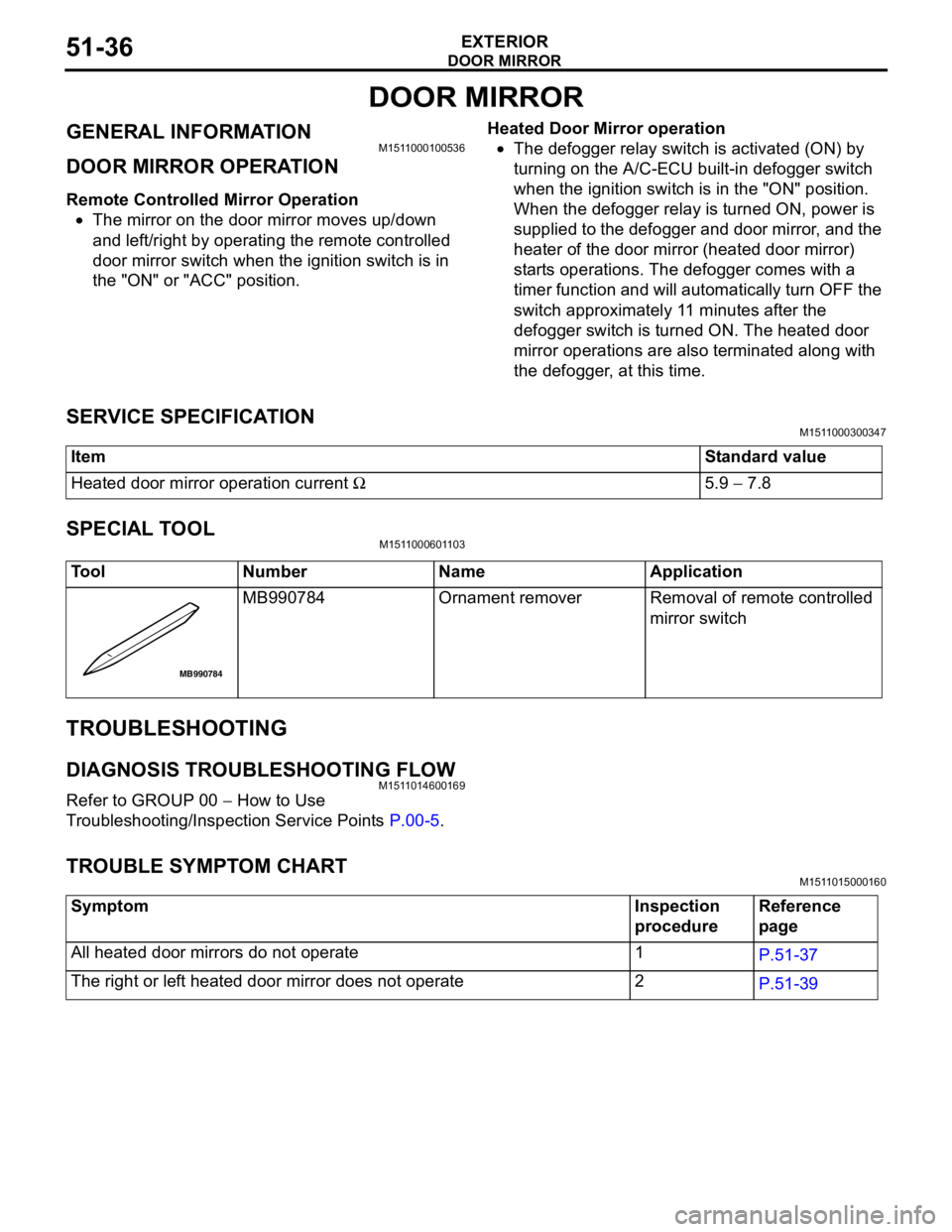
DOOR MIRROR
EXTERIOR51-36
DOOR MIRROR
GENERAL INFORMATIONM1511000100536
DOOR MIRROR OPERATION
Remote Controlled Mirror Operation
•The mirror on the door mirror moves up/down
and left/right by operating the remote controlled
door mirror switch when the ignition switch is in
the "ON" or "ACC" position.Heated Door Mirror operation
•The defogger relay switch is activated (ON) by
turning on the A/C-ECU built-in defogger switch
when the ignition switch is in the "ON" position.
When the defogger relay is turned ON, power is
supplied to the defogger and door mirror, and the
heater of the door mirror (heated door mirror)
starts operations. The defogger comes with a
timer function and will automatically turn OFF the
switch approximately 11 minutes after the
defogger switch is turned ON. The heated door
mirror operations are also terminated along with
the defogger, at this time.
SERVICE SPECIFICATIONM1511000300347
SPECIAL TOOLM1511000601103
TROUBLESHOOTING
DIAGNOSIS TROUBLESHOOTING FLOWM1511014600169
Refer to GROUP 00 − How to Use
Troubleshooting/Inspection Service Points P.00-5.
TROUBLE SYMPTOM CHARTM1511015000160
ItemStandard value
Heated door mirror operation current Ω5.9 − 7.8
Tool Number Name Application
MB990784 Ornament remover Removal of remote controlled
mirror switch
MB990784
Symptom Inspection
procedureReference
page
All heated door mirrors do not operate 1
P.51-37
The right or left heated door mirror does not operate 2
P.51-39