manual clutch MITSUBISHI LANCER 2005 Workshop Manual
[x] Cancel search | Manufacturer: MITSUBISHI, Model Year: 2005, Model line: LANCER, Model: MITSUBISHI LANCER 2005Pages: 788, PDF Size: 45.98 MB
Page 1 of 788
GROUP INDEX
00General . . . . . . . . . . . . . . . . . . . . . . . .
11Engine. . . . . . . . . . . . . . . . . . . . . . . . .
12Engine Lubrication . . . . . . . . . . . . . .
13Fuel . . . . . . . . . . . . . . . . . . . . . . . . . . .
14Engine Cooling . . . . . . . . . . . . . . . . .
15Intake and Exhaust . . . . . . . . . . . . . .
16Engine Electrical . . . . . . . . . . . . . . . .
17Engine and Emission Control . . . . .
21Clutch . . . . . . . . . . . . . . . . . . . . . . . . .
22Manual Transmission . . . . . . . . . . . .
23Automatic Transmission. . . . . . . . . .
26Front Axle . . . . . . . . . . . . . . . . . . . . . .
27Rear Axle . . . . . . . . . . . . . . . . . . . . . .
31Wheel and Tyre . . . . . . . . . . . . . . . . .
32Power Plant Mount . . . . . . . . . . . . . .
33Front Suspension . . . . . . . . . . . . . . .
34Rear Suspension . . . . . . . . . . . . . . . .
35Service Brakes . . . . . . . . . . . . . . . . . .
36Parking Brakes . . . . . . . . . . . . . . . . .
37Power Steering . . . . . . . . . . . . . . . . .
42Body . . . . . . . . . . . . . . . . . . . . . . . . . .
51Exterior . . . . . . . . . . . . . . . . . . . . . . . .
52 . . . . . . . . . .
54Chassis Electrical . . . . . . . . . . . . . . .
55 . . . . . . .
70Component Locations. . . . . . . . . . . .
80Configration Diagrams . . . . . . . . . . .
90Circuit Diagrams . . . . . . . . . . . . . . . .
LANCER /
LANCER WAGON
WORKSHOP MANUAL
FOREWORD
This Workshop manual contains procedures for
service mechanics, including removal, disassembly,
inspection, adjustment, reassembly and installation.
Use the following manuals in combination with this
manual as required.
TECHNICAL INFORMATION MANUAL
PYME0302
PYME0302-A
WORKSHOP MANUAL
CHASSIS GROUP PWME0302
BODY REPAIR MANUAL
PBME0302
PBME0302-A
PARTS CATALOGUE
B606K005A_
All information, illustrations and product descriptions
contained in this manual are current as at the time of
publication. We, however, reserve the right to make
changes at any time without prior notice or obligation.
Mitsubishi Motors Corporation May 2004
Heater, Air Conditioner and
Ventilation Interior and Supplemental
Restraint System (SRS)
Page 496 of 788
TROUBLESHOOTING
HEATER, AIR CONDITIONER AND VENTILATION55-12
COMMENTS ON TROUBLE SYMPTOM
If cool air is not distributed when the A/C switch is on,
the air thermo sensor or the A/C compressor relay
system may be defective.
TROUBLESHOOTING HINTS
•Improper amount of refrigerant
•Malfunction of the air thermo sensor
•Malfunction of the dual pressure switch
•Malfunction of the A/C compressor relay
•Malfunction of the A/C refrigerant temperature
switch
•Malfunction of the magnetic clutch
•Malfunction of the manual air conditioner control
panel (A/C-ECU)
•Damaged the wiring harness or connectors
•Malfunction of the engine-ECU
engine-A/T-ECU
DIAGNOSIS
STEP 1. Check the defogger and outside/inside
air selection damper control motor operation.
Q: Do the defogger and outside/inside air selection
damper control motor work normally?
YES :
Go to Step 2.
NO : Refer to Inspection procedure 9
"Malfunction of the A/C-ECU power supply
system
STEP 2. Check the blower motor operation.
Q: Does the blower motor work normally?
YES :
Go to Step 3.
NO : Refer to Inspection procedure 5 "Blower fan
and motor do not turn P.55-29."
STEP 3. Check the A/C compressor.
Check the A/C compressor for compressor oil leaks.
Q: Is the check result satisfactory?
YES :
Go to Step 4.
NO : Replace the A/C compressor or the
expansion valve.
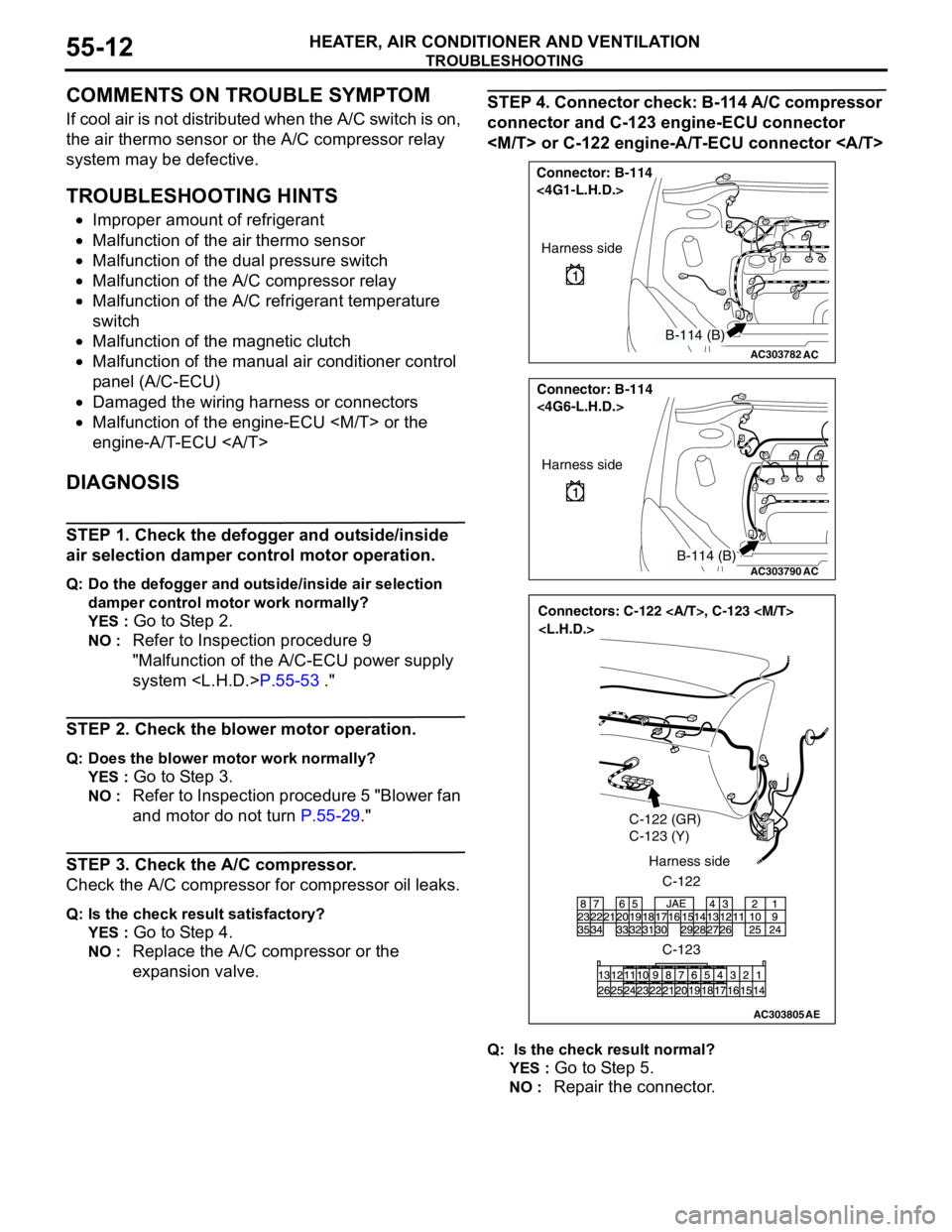
STEP 4. Connector check: B-114 A/C compressor
connector and C-123 engine-ECU connector
Q: Is the check result normal?
YES :
Go to Step 5.
NO : Repair the connector.
AC303782
Connector: B-114
<4G1-L.H.D.>
AC
Harness side
B-114 (B)
AC303790
Connector: B-114
<4G6-L.H.D.>
AC
Harness side
B-114 (B)
AC303805
Connectors: C-122 , C-123
C-122 (GR)
C-123 (Y)
C-122 Harness side
C-123
AE
Page 505 of 788
TROUBLESHOOTING
HEATER, AIR CONDITIONER AND VENTILATION55-21
COMMENTS ON TROUBLE SYMPTOM
If cool air is not distributed when the A/C switch is on,
the air thermo sensor or the A/C compressor relay
system may be defective.
TROUBLESHOOTING HINTS
•Improper amount of refrigerant
•Malfunction of the air thermo sensor
•Malfunction of the dual pressure switch
•Malfunction of the A/C compressor relay
•Malfunction of the A/C refrigerant temperature
switch
•Malfunction of the magnetic clutch
•Malfunction of the manual air conditioner control
panel (A/C-ECU)
•Damaged the wiring harness or connectors
•Malfunction of the engine-ECU
engine-A/T-ECU
DIAGNOSIS
STEP 1. Check the defogger and outside/inside
air selection damper control motor operation.
Q: Do the defogger and outside/inside air selection
damper control motor work normally?
YES :
Go to Step 2.
NO : Refer to Inspection procedure 10
"Malfunction of the A/C-ECU power supply
system
STEP 2. Check the blower motor operation.
Q: Does the blower motor work normally?
YES :
Go to Step 3.
NO : Refer to Inspection procedure 5 "Blower fan
and motor do not turn P.55-29."
STEP 3. Check the A/C compressor.
Check the A/C compressor for compressor oil leaks.
Q: Is the check result satisfactory?
YES :
Go to Step 4.
NO : Replace the A/C compressor or the
expansion valve.
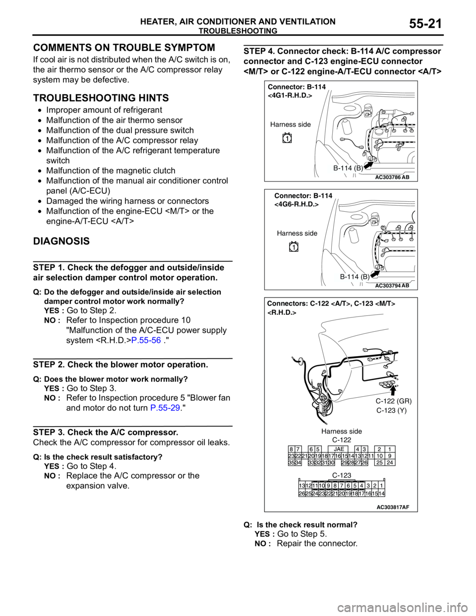
STEP 4. Connector check: B-114 A/C compressor
connector and C-123 engine-ECU connector
Q: Is the check result normal?
YES :
Go to Step 5.
NO : Repair the connector.
AC303786
Connector: B-114
<4G1-R.H.D.>
AB
Harness side
B-114 (B)
AC303794
Connector: B-114
<4G6-R.H.D.>
AB
Harness side
B-114 (B)
AC303817
Connectors: C-122 , C-123
AF
C-122C-122 (GR)
C-123 (Y)
C-123 Harness side
Page 754 of 788
MANUAL AIR CONDITIONER
CIRCUIT DIAGRAMS90-116
MANUAL AIR CONDITIONER
FUSIBLE
LINK2ENGINE
CONTROL
RELAY
RADIATOR
FAN RELAY
SMOOTHING
CIRCUIT
INPUT
SIGNAL
PROCESSING
DRIVE
CIRCUIT
TEMPERATURE
DETECTIONCURRENT
DETECTIONRADIATOR
FAN MOTOR COOLING FAN MOTOR
DRIVE CONTROL UNIT
CONDENSER
FAN MOTOR
NOTE
: M/T
: A/T
: EXCEPT 4G6
: 4G6
Wire colour code
B : Black LG : Light green G : Green L : Blue W : White Y : Yellow SB : Sky blue
BR : Brown O : Orange GR : Gray R : Red P : Pink V : Violet
FIELD EFFECT
TRANSISTOR
CIRCUIT BATTERYA/C-ECU
RELAY
BOX
A/C COMPRESSOR
RELAY
A/C COMPRESSOR
A/C
REFRIGERANT
TEMPERATURE
SWITCH
MAGNETIC
CLUTCHLOW-
PRESSURE
SIDE
HIGH-
PRESSURE
SIDE
DUAL
PRESSURE
SWITCH
ENGINE-
ECU
ENGINE-
A/T-ECU
(FUSE )5
Page 756 of 788
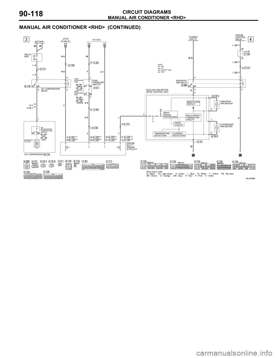
MANUAL AIR CONDITIONER
CIRCUIT DIAGRAMS90-118
MANUAL AIR CONDITIONER
FUSIBLE
LINK2ENGINE
CONTROL
RELAY
RADIATOR
FAN RELAY
SMOOTHING
CIRCUIT
INPUT
SIGNAL
PROCESSING
DRIVE
CIRCUIT
TEMPERATURE
DETECTIONCURRENT
DETECTIONRADIATOR
FAN MOTOR COOLING FAN MOTOR
DRIVE CONTROL UNIT
CONDENSER
FAN MOTOR
Wire colour code
B : Black LG : Light green G : Green L : Blue W : White Y : Yellow SB : Sky blue
BR : Brown O : Orange GR : Gray R : Red P : Pink V : Violet FIELD EFFECT
TRANSISTOR
CIRCUIT
NOTE
: M/T
: A/T
: EXCEPT 4G6
: 4G6
BATTERYA/C-ECU
A/C COMPRESSOR
RELAY
A/C COMPRESSOR
A/C
REFRIGERANT
TEMPERATURE
SWITCH
MAGNETIC
CLUTCHLOW-
PRESSURE
SIDE
HIGH-
PRESSURE
SIDE
DUAL
PRESSURE
SWITCH
ENGINE-
ECU
ENGINE-
A/T-ECU
RELAY
BOX
(FUSE )5