warning light MITSUBISHI LANCER 2005 Workshop Manual
[x] Cancel search | Manufacturer: MITSUBISHI, Model Year: 2005, Model line: LANCER, Model: MITSUBISHI LANCER 2005Pages: 788, PDF Size: 45.98 MB
Page 66 of 788
CHARGING SYSTEM
ENGINE ELECTRICAL16-2
CHARGING SYSTEM
GENERAL INFORMATIONM1161000100522
The charging system uses the alternator output to
keep the battery charged at a constant level under
various electrical loads.
OPERATION
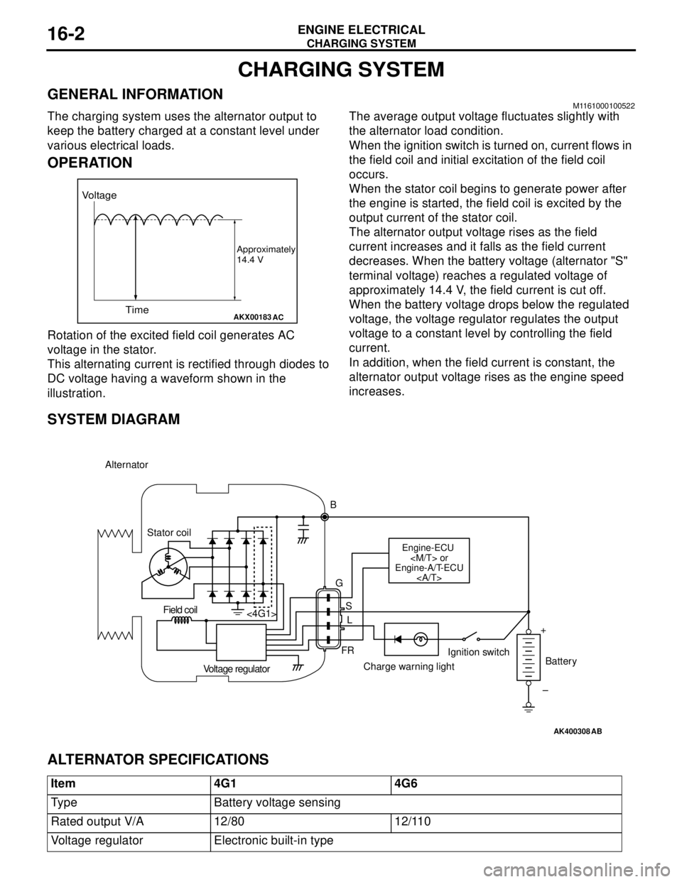
Rotation of the excited field coil generates AC
voltage in the stator.
This alternating current is rectified through diodes to
DC voltage having a waveform shown in the
illustration.The average output voltage fluctuates slightly with
the alternator load condition.
When the ignition switch is turned on, current flows in
the field coil and initial excitation of the field coil
occurs.
When the stator coil begins to generate power after
the engine is started, the field coil is excited by the
output current of the stator coil.
The alternator output voltage rises as the field
current increases and it falls as the field current
decreases. When the battery voltage (alternator "S"
terminal voltage) reaches a regulated voltage of
approximately 14.4 V, the field current is cut off.
When the battery voltage drops below the regulated
voltage, the voltage regulator regulates the output
voltage to a constant level by controlling the field
current.
In addition, when the field current is constant, the
alternator output voltage rises as the engine speed
increases.
SYSTEM DIAGRAM
ALTERNATOR SPECIFICATIONS
AKX00183
Voltage
Time
Approximately
14.4 V
AC
AK400308
Alternator
B
Stator coil
Engine-ECU
Engine-A/T-ECU
G
S
L
FR <4G1>
Voltage regulatorCharge warning lightIgnition switch
Battery Field coil
+
–
AB
Item 4G1 4G6
Type Battery voltage sensing
Rated output V/A 12/80 12/110
Voltage regulator Electronic built-in type
Page 69 of 788
CHARGING SYSTEM
ENGINE ELECTRICAL16-5
OUTPUT CURRENT TESTM1161001000368
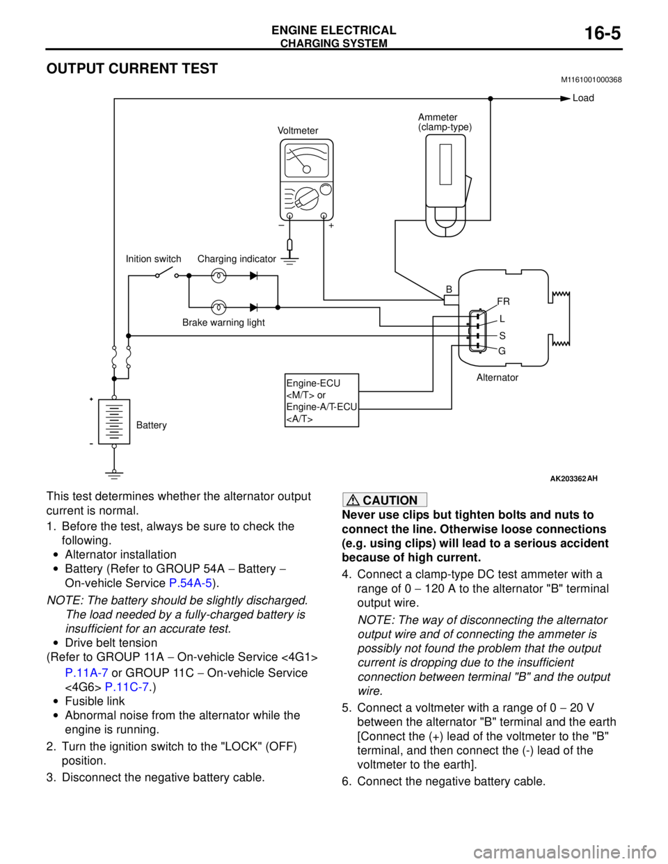
This test determines whether the alternator output
current is normal.
1. Before the test, always be sure to check the
following.
•Alternator installation
•Battery (Refer to GROUP 54A − Battery −
On-vehicle Service P.54A-5).
NOTE: The battery should be slightly discharged.
The load needed by a fully-charged battery is
insufficient for an accurate test.
•Drive belt tension
(Refer to GROUP 11A − On-vehicle Service <4G1>
P.11A-7 or GROUP 11C − On-vehicle Service
<4G6> P.11C-7.)
•Fusible link
•Abnormal noise from the alternator while the
engine is running.
2. Turn the ignition switch to the "LOCK" (OFF)
position.
3. Disconnect the negative battery cable.CAUTION
Never use clips but tighten bolts and nuts to
connect the line. Otherwise loose connections
(e.g. using clips) will lead to a serious accident
because of high current.
4. Connect a clamp-type DC test ammeter with a
range of 0 − 120 A to the alternator "B" terminal
output wire.
NOTE: The way of disconnecting the alternator
output wire and of connecting the ammeter is
possibly not found the problem that the output
current is dropping due to the insufficient
connection between terminal "B" and the output
wire.
5. Connect a voltmeter with a range of 0 − 20 V
between the alternator "B" terminal and the earth
[Connect the (+) lead of the voltmeter to the "B"
terminal, and then connect the (-) lead of the
voltmeter to the earth].
6. Connect the negative battery cable.
AK203362
Alternator Ammeter
(clamp-type)
Voltmeter
Battery Inition switch
Engine-ECU
Engine-A/T-ECU
Load
B
FR
L
S
G +
AH
–
Charging indicator
Brake warning light
Page 183 of 788
33-1
GROUP 33
FRONT
SUSPENSION
CONTENTS
GENERAL INFORMATION . . . . . . . .33-2
SERVICE SPECIFICATIONS . . . . . . .33-3
LUBRICANT . . . . . . . . . . . . . . . . . . . .33-3
SPECIAL TOOLS . . . . . . . . . . . . . . . .33-4
ON-VEHICLE SERVICE . . . . . . . . . . .33-5
FRONT WHEEL ALIGNMENT CHECK
AND ADJUSTMENT . . . . . . . . . . . . . . . . . . 33-5
LOWER ARM BALL JOINT AXIAL PLAY
CHECK . . . . . . . . . . . . . . . . . . . . . . . . . . . . 33-6
LOWER ARM BALL JOINT COVER
CHECK . . . . . . . . . . . . . . . . . . . . . . . . . . . . 33-6
STRUT ASSEMBLY . . . . . . . . . . . . . .33-7
REMOVAL AND INSTALLATION . . . . . . . . 33-7
INSPECTION . . . . . . . . . . . . . . . . . . . . . . . . 33-7
DISASSEMBLY AND REASSEMBLY . . . . . 33-8
INSPECTION . . . . . . . . . . . . . . . . . . . . . . . . 33-10
LOWER ARM . . . . . . . . . . . . . . . . . . .33-11
REMOVAL AND INSTALLATION . . . . . . . . 33-11
INSPECTION . . . . . . . . . . . . . . . . . . . . . . . . 33-12
LOWER ARM BALL JOINT COVER
REPLACEMENT . . . . . . . . . . . . . . . . . . . . . 33-12
LOWER ARM BUSHING (REAR)
REPLACEMENT . . . . . . . . . . . . . . . . . . . . . 33-13
STABILIZER BAR* . . . . . . . . . . . . . . .33-14
REMOVAL AND INSTALLATION . . . . . . . . 33-14
INSPECTION . . . . . . . . . . . . . . . . . . . . . . . . 33-17
WARNINGS REGARDING SERVICING OF SUPPLEMENTAL RESTRAINT SYSTEM (SRS) EQUIPPED VEHICLES
WARNING
•Improper service or maintenance of any component of the SRS, or any SRS-related component, can lead to
personal injury or death to service personnel (from inadvertent firing of the air bag) or to the driver and
paassenger (from rendering the SRS inoperative).
•Service or maintenance of any SRS component or SRS-related component must be performed only at an
authorized MITSUBISHI dealer.
•MITSUBISHI dealer personnel must thoroughly review this manual, and especially its GROUP 52B - Supplemental
Restraint System (SRS) before beginning any service or maintenance of any component of the SRS or any
SRS-related component.
NOTE
The SRS includes the following components: SRS air bag control unit, SRS warning light, front impact sensors, air bag module,
clock spring, and interconnecting wiring. Other SRS-related components (that may have to be removed/installed in connection
with SRS service or maintenance) are indicated in the table of contents by an asterisk (*).
Page 235 of 788
37-1
GROUP 37
POWER STEERING
CONTENTS
GENERAL INFORMATION . . . . . . . .37-3
SERVICE SPECIFICATIONS . . . . . . .37-6
LUBRICANTS . . . . . . . . . . . . . . . . . .37-7
SEALANTS . . . . . . . . . . . . . . . . . . . .37-7
SPECIAL TOOLS . . . . . . . . . . . . . . . .37-8
ON-VEHICLE SERVICE . . . . . . . . . . .37-11
STEERING WHEEL FREE PLAY
CHECK . . . . . . . . . . . . . . . . . . . . . . . . . . . . 37-11
STEERING ANGLE CHECK . . . . . . . . . . . . 37-11
TIE ROD END BALL JOINT TURNING
TORQUE CHECK . . . . . . . . . . . . . . . . . . . . 37-12
STATIONARY STEERING EFFORT
CHECK . . . . . . . . . . . . . . . . . . . . . . . . . . . . 37-12
STEERING WHEEL RETURN TO
CENTRE CHECK . . . . . . . . . . . . . . . . . . . . 37-13DRIVE BELT TENSION CHECK . . . . . . . . . 37-13
FLUID LEVEL CHECK . . . . . . . . . . . . . . . . 37-13
FLUID REPLACEMENT . . . . . . . . . . . . . . . 37-13
POWER STEERING SYSTEM AIR
BLEEDING . . . . . . . . . . . . . . . . . . . . . . . . . 37-13
OIL PUMP PRESSURE TEST . . . . . . . . . . 37-14
POWER STEERING PRESSURE
SWITCH CHECK . . . . . . . . . . . . . . . . . . . . . 37-15
TIE ROD END BALL JOINT DUST COVER
CHECK . . . . . . . . . . . . . . . . . . . . . . . . . . . . 37-15
STEERING COLUMN SHAFT
ASSEMBLY SHOCK ABSORBING
MECHANISM CHECK . . . . . . . . . . . . . . . . . 37-15
STEERING WHEEL* . . . . . . . . . . . . . .37-17
REMOVAL AND INSTALLATION
REMOVAL AND INSTALLATION
Continued on next page
WARNINGS REGARDING SERVICING OF SUPPLEMENTAL RESTRAINT SYSTEM (SRS) EQUIPPED VEHICLES
WARNING
•Improper service or maintenance of any component of the SRS, or any SRS-related component, can lead to
personal injury or death to service personnel (from inadvertent firing of the air bag) or to the driver and
paassenger (from rendering the SRS inoperative).
•Service or maintenance of any SRS component or SRS-related component must be performed only at an
authorized MITSUBISHI dealer.
•MITSUBISHI dealer personnel must thoroughly review this manual, and especially its GROUP 52B - Supplemental
Restraint System (SRS) before beginning any service or maintenance of any component of the SRS or any
SRS-related component.
NOTE
The SRS includes the following components: SRS air bag control unit, SRS warning light, front impact sensors, air bag module,
clock spring, and interconnecting wiring. Other SRS-related components (that may have to be removed/installed in connection
with SRS service or maintenance) are indicated in the table of contents by an asterisk (*).
Page 389 of 788
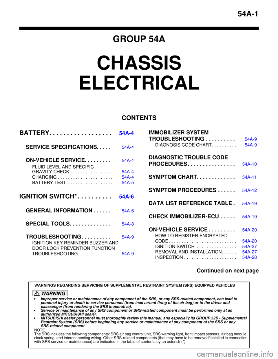
54A-1
GROUP 54A
CHASSIS
ELECTRICAL
CONTENTS
BATTERY. . . . . . . . . . . . . . . . . .
54A-4
SERVICE SPECIFICATIONS. . . . .
54A-4
ON-VEHICLE SERVICE. . . . . . . . .54A-4
FLUID LEVEL AND SPECIFIC
GRAVITY CHECK . . . . . . . . . . . . . . . . . 54A-4
CHARGING . . . . . . . . . . . . . . . . . . . . . . 54A-4
BATTERY TEST . . . . . . . . . . . . . . . . . . 54A-5
IGNITION SWITCH* . . . . . . . . . .54A-6
GENERAL INFORMATION . . . . . .
54A-6
SPECIAL TOOLS. . . . . . . . . . . . . .54A-8
TROUBLESHOOTING . . . . . . . . . .54A-9
IGNITION KEY REMINDER BUZZER AND
DOOR LOCK PREVENTION FUNCTION
TROUBLESHOOTING . . . . . . . . . . . . . . 54A-9
IMMOBILIZER SYSTEM
TROUBLESHOOTING . . . . . . . . . .
54A-9
DIAGNOSIS CODE CHART . . . . . . . . . . 54A-9
DIAGNOSTIC TROUBLE CODE
PROCEDURES . . . . . . . . . . . . . . . .
54A-10
SYMPTOM CHART. . . . . . . . . . . . .54A-11
SYMPTOM PROCEDURES . . . . . .54A-12
DATA LIST REFERENCE TABLE .54A-19
CHECK IMMOBILIZER-ECU . . . . .54A-19
ON-VEHICLE SERVICE . . . . . . . . .54A-20
HOW TO REGISTER ENCRYPTED
CODE . . . . . . . . . . . . . . . . . . . . . . . . . . . 54A-20
IGNITION SWITCH . . . . . . . . . . . . . . . . 54A-27
REMOVAL AND INSTALLATION . . . . . . 54A-27
INSPECTION . . . . . . . . . . . . . . . . . . . . . 54A-28
Continued on next page
WARNINGS REGARDING SERVICING OF SUPPLEMENTAL RESTRAINT SYSTEM (SRS) EQUIPPED VEHICLES
WARNING
•Improper service or maintenance of any component of the SRS, or any SRS-related component, can lead to
personal injury or death to service personnel (from inadvertent firing of the air bag) or to the driver and
paassenger (from rendering the SRS inoperative).
•Service or maintenance of any SRS component or SRS-related component must be performed only at an
authorized MITSUBISHI dealer.
•MITSUBISHI dealer personnel must thoroughly review this manual, and especially its GROUP 52B - Supplemental
Restraint System (SRS) before beginning any service or maintenance of any component of the SRS or any
SRS-related component.
NOTE
The SRS includes the following components: SRS air bag control unit, SRS warning light, front impact sensors, air bag module,
clock spring, and interconnecting wiring. Other SRS-related components (that may have to be removed/installed in connection
with SRS service or maintenance) are indicated in the table of contents by an asterisk (*).
Page 391 of 788
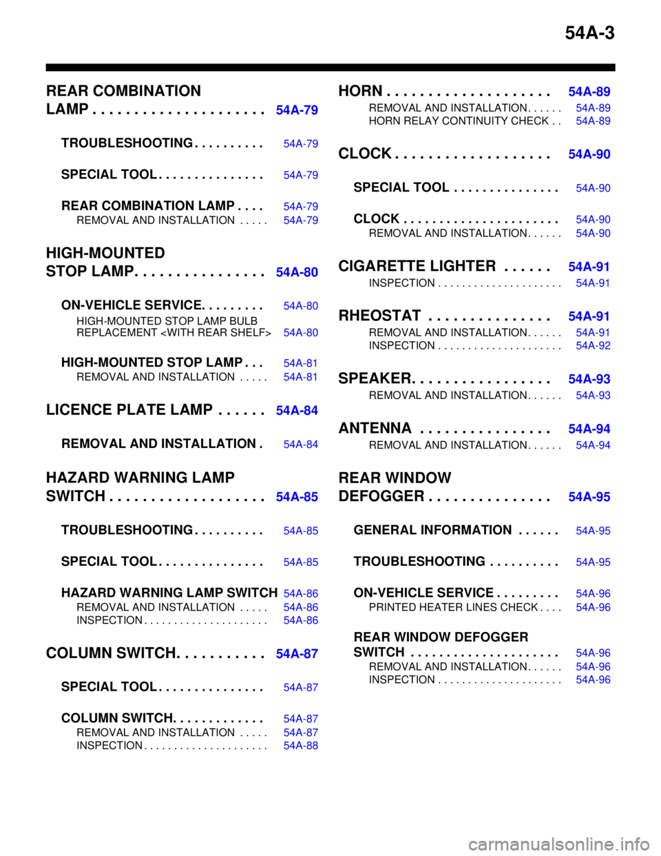
54A-3
REAR COMBINATION
LAMP . . . . . . . . . . . . . . . . . . . . .
54A-79
TROUBLESHOOTING . . . . . . . . . .
54A-79
SPECIAL TOOL . . . . . . . . . . . . . . .54A-79
REAR COMBINATION LAMP . . . .54A-79
REMOVAL AND INSTALLATION . . . . . 54A-79
HIGH-MOUNTED
STOP LAMP. . . . . . . . . . . . . . . .
54A-80
ON-VEHICLE SERVICE. . . . . . . . .
54A-80
HIGH-MOUNTED STOP LAMP BULB
REPLACEMENT
HIGH-MOUNTED STOP LAMP . . .54A-81
REMOVAL AND INSTALLATION . . . . . 54A-81
LICENCE PLATE LAMP . . . . . .54A-84
REMOVAL AND INSTALLATION .
54A-84
HAZARD WARNING LAMP
SWITCH . . . . . . . . . . . . . . . . . . .
54A-85
TROUBLESHOOTING . . . . . . . . . .
54A-85
SPECIAL TOOL . . . . . . . . . . . . . . .54A-85
HAZARD WARNING LAMP SWITCH54A-86
REMOVAL AND INSTALLATION . . . . . 54A-86
INSPECTION . . . . . . . . . . . . . . . . . . . . . 54A-86
COLUMN SWITCH. . . . . . . . . . .54A-87
SPECIAL TOOL . . . . . . . . . . . . . . .
54A-87
COLUMN SWITCH. . . . . . . . . . . . .54A-87
REMOVAL AND INSTALLATION . . . . . 54A-87
INSPECTION . . . . . . . . . . . . . . . . . . . . . 54A-88
HORN . . . . . . . . . . . . . . . . . . . . 54A-89
REMOVAL AND INSTALLATION . . . . . . 54A-89
HORN RELAY CONTINUITY CHECK . . 54A-89
CLOCK . . . . . . . . . . . . . . . . . . . 54A-90
SPECIAL TOOL . . . . . . . . . . . . . . .
54A-90
CLOCK . . . . . . . . . . . . . . . . . . . . . .54A-90
REMOVAL AND INSTALLATION . . . . . . 54A-90
CIGARETTE LIGHTER . . . . . . 54A-91
INSPECTION . . . . . . . . . . . . . . . . . . . . . 54A-91
RHEOSTAT . . . . . . . . . . . . . . . 54A-91
REMOVAL AND INSTALLATION . . . . . . 54A-91
INSPECTION . . . . . . . . . . . . . . . . . . . . . 54A-92
SPEAKER. . . . . . . . . . . . . . . . . 54A-93
REMOVAL AND INSTALLATION . . . . . . 54A-93
ANTENNA . . . . . . . . . . . . . . . . 54A-94
REMOVAL AND INSTALLATION . . . . . . 54A-94
REAR WINDOW
DEFOGGER . . . . . . . . . . . . . . .
54A-95
GENERAL INFORMATION . . . . . .
54A-95
TROUBLESHOOTING . . . . . . . . . .54A-95
ON-VEHICLE SERVICE . . . . . . . . .54A-96
PRINTED HEATER LINES CHECK . . . . 54A-96
REAR WINDOW DEFOGGER
SWITCH . . . . . . . . . . . . . . . . . . . . .
54A-96
REMOVAL AND INSTALLATION . . . . . . 54A-96
INSPECTION . . . . . . . . . . . . . . . . . . . . . 54A-96
Page 640 of 788
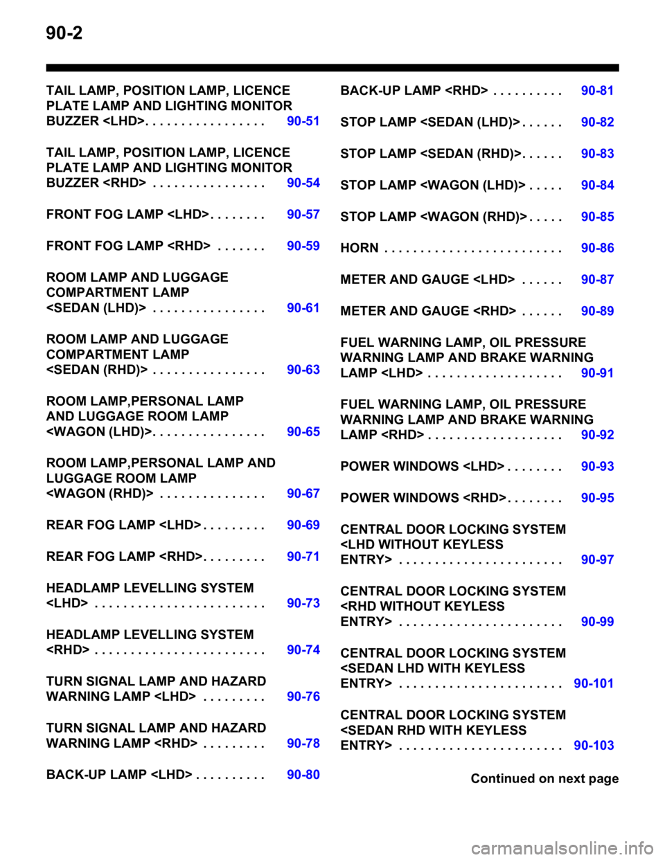
90-2
TAIL LAMP, POSITION LAMP, LICENCE
PLATE LAMP AND LIGHTING MONITOR
BUZZER
TAIL LAMP, POSITION LAMP, LICENCE
PLATE LAMP AND LIGHTING MONITOR
BUZZER
FRONT FOG LAMP
FRONT FOG LAMP
ROOM LAMP AND LUGGAGE
COMPARTMENT LAMP
ROOM LAMP AND LUGGAGE
COMPARTMENT LAMP
ROOM LAMP,PERSONAL LAMP
AND LUGGAGE ROOM LAMP
ROOM LAMP,PERSONAL LAMP AND
LUGGAGE ROOM LAMP
REAR FOG LAMP
REAR FOG LAMP
HEADLAMP LEVELLING SYSTEM
HEADLAMP LEVELLING SYSTEM
TURN SIGNAL LAMP AND HAZARD
WARNING LAMP
TURN SIGNAL LAMP AND HAZARD
WARNING LAMP
BACK-UP LAMP
STOP LAMP
STOP LAMP
STOP LAMP
STOP LAMP
HORN . . . . . . . . . . . . . . . . . . . . . . . . .90-86
METER AND GAUGE
METER AND GAUGE
FUEL WARNING LAMP, OIL PRESSURE
WARNING LAMP AND BRAKE WARNING
LAMP
FUEL WARNING LAMP, OIL PRESSURE
WARNING LAMP AND BRAKE WARNING
LAMP
POWER WINDOWS
POWER WINDOWS
CENTRAL DOOR LOCKING SYSTEM
CENTRAL DOOR LOCKING SYSTEM
CENTRAL DOOR LOCKING SYSTEM
CENTRAL DOOR LOCKING SYSTEM
Continued on next page
Page 644 of 788
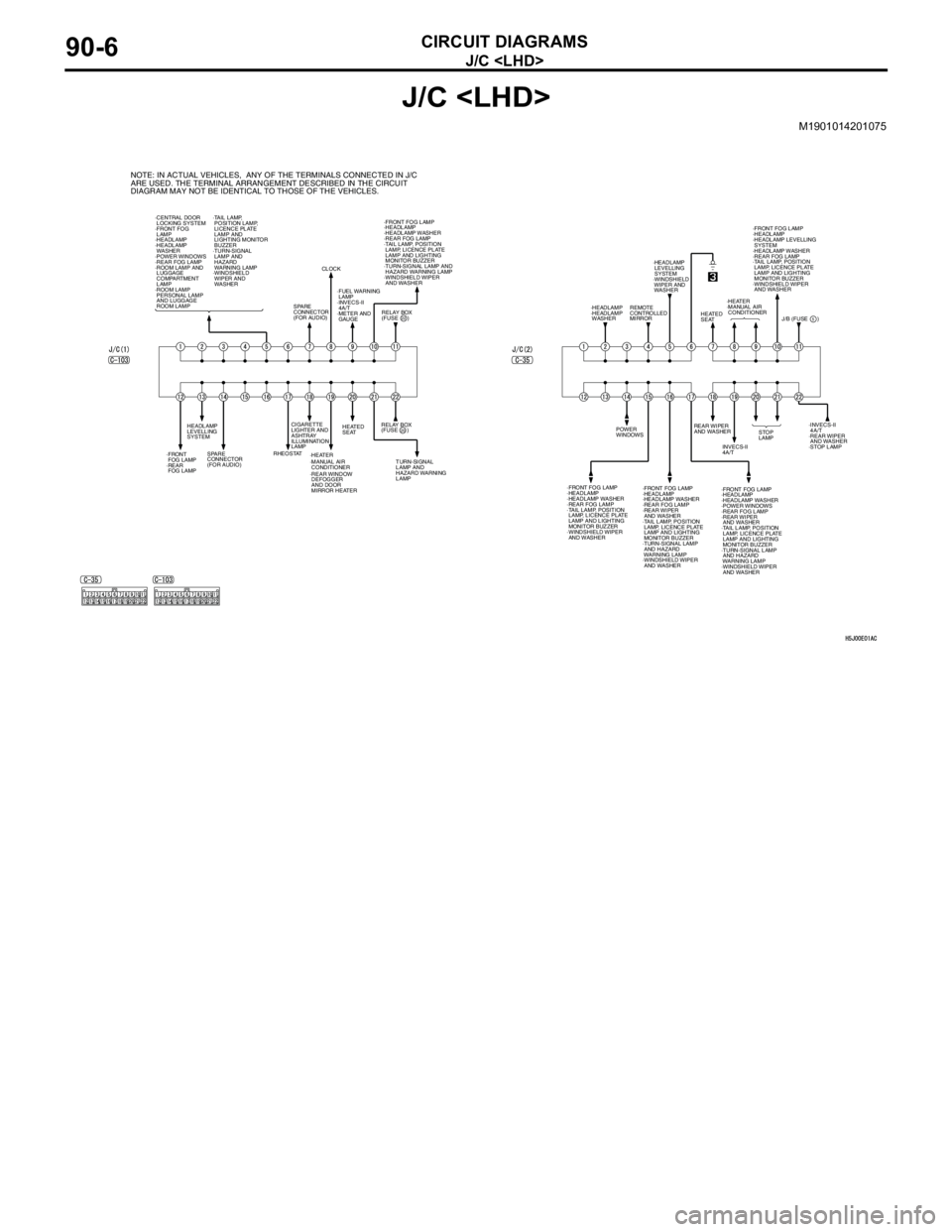
J/C
CIRCUIT DIAGRAMS90-6
J/C
M1901014201075
NOTE: IN ACTUAL VEHICLES, ANY OF THE TERMINALS CONNECTED IN J/C
ARE USED. THE TERMINAL ARRANGEMENT DESCRIBED IN THE CIRCUIT
DIAGRAM MAY NOT BE IDENTICAL TO THOSE OF THE VEHICLES.
·CENTRAL DOOR
LOCKING SYSTEM
·FRONT FOG
LAMP
·HEADLAMP
·HEADLAMP
WASHER
·POWER WINDOWS
·REAR FOG LAMP
·ROOM LAMP AND
LUGGAGE
COMPARTMENT
LAMP
·ROOM LAMP
PERSONAL LAMP
AND LUGGAGE
ROOM LAMP ·TAIL LAMP,
POSITION LAMP,
LICENCE PLATE
LAMP AND
LIGHTING MONITOR
BUZZER
·TURN-SIGNAL
LAMP AND
HAZARD
WARNING LAMP
·WINDSHIELD
WIPER AND
WASHER
RELAY BOX
(FUSE )·FRONT FOG LAMP
·HEADLAMP
·HEADLAMP WASHER
·REAR FOG LAMP
·TAIL LAMP, POSITION
LAMP, LICENCE PLATE
LAMP AND LIGHTING
MONITOR BUZZER
·TURN-SIGNAL LAMP AND
HAZARD WARNING LAMP
·WINDSHIELD WIPER
AND WASHER
SPARE
CONNECTOR
(FOR AUDIO)CLOCK
·FUEL WARNING
LAMP
·INVECS-II
4A/T
·METER AND
GAUGE
RELAY BOX
(FUSE )
TURN-SIGNAL
LAMP AND
HAZARD WARNING
LAMP HEATED
SEAT
·HEATER CIGARETTE
LIGHTER AND
ASHTRAY
ILLUMINATION
LAMP
RHEOSTAT
SPARE
CONNECTOR
(FOR AUDIO) HEADLAMP
LEVELLING
SYSTEM
·FRONT
FOG LAMP
·REAR
FOG LAMP
20
22
·REAR WINDOW
DEFOGGER
AND DOOR
MIRROR HEATER ·MANUAL AIR
CONDITIONERREAR WIPER
AND WASHER
·FRONT FOG LAMP
·HEADLAMP
·HEADLAMP WASHER
·REAR FOG LAMP
·TAIL LAMP, POSITION
LAMP, LICENCE PLATE
LAMP AND LIGHTING
MONITOR BUZZER
·WINDSHIELD WIPER
AND WASHERINVECS-II
4A/T POWER
WINDOWSSTOP
LAMP·INVECS-II
4A/T
·REAR WIPER
AND WASHER
·STOP LAMP
·FRONT FOG LAMP
·HEADLAMP
·HEADLAMP WASHER
·REAR FOG LAMP
·REAR WIPER
AND WASHER
·TAIL LAMP, POSITION
LAMP, LICENCE PLATE
LAMP AND LIGHTING
MONITOR BUZZER
·TURN-SIGNAL LAMP
AND HAZARD
WARNING LAMP
·WINDSHIELD WIPER
AND WASHER·FRONT FOG LAMP
·HEADLAMP
·HEADLAMP WASHER
·POWER WINDOWS
·REAR FOG LAMP
·REAR WIPER
AND WASHER
·TAIL LAMP, POSITION
LAMP, LICENCE PLATE
LAMP AND LIGHTING
MONITOR BUZZER
·TURN-SIGNAL LAMP
AND HAZARD
WARNING LAMP
·WINDSHIELD WIPER
AND WASHER·FRONT FOG LAMP
·HEADLAMP
·HEADLAMP LEVELLING
SYSTEM
·HEADLAMP WASHER
·REAR FOG LAMP
·TAIL LAMP, POSITION
LAMP, LICENCE PLATE
LAMP AND LIGHTING
MONITOR BUZZER
·WINDSHIELD WIPER
AND WASHER
·HEATER
·MANUAL AIR
CONDITIONER
J/B (FUSE ) HEATED
SEAT ·HEADLAMP
LEVELLING
SYSTEM
·WINDSHIELD
WIPER AND
WASHER
REMOTE
CONTROLLED
MIRROR ·HEADLAMP
·HEADLAMP
WASHER
5
Page 645 of 788
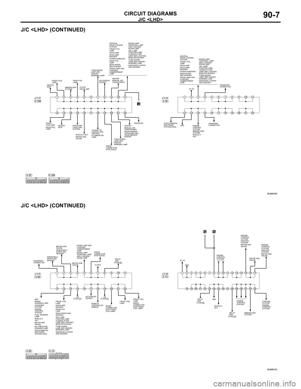
J/C
CIRCUIT DIAGRAMS90-7
J/C
J/C
FRONT FOG
LAMP
·FRONT
FOG LAMP·FRONT FOG
LAMP
REAR FOG
LAMP
·REAR FOG
LAMP·REAR FOG
LAMP
HEATED
SEAT
HEATED
SEATIMMOBILIZER
SYSTEM·CLOCK·HEATER TURN-SIGNAL
LAMP AND
HAZARD
WARNING LAMP·TURN-SIGNAL
LAMP AND HAZARD
WARNING LAMP
TURN-SIGNAL
LAMP AND
HAZARD
WARNING LAMP ·MANUAL AIR
CONDITIONER
·HEATER
·MANUAL AIR
CONDITIONER ·HEADLAMP·HEADLAMP
·HEADLAMP
WASHER
ACCESSORY
SOCKET·CENTRAL
DOOR LOCKING
SYSTEM
·POWER WINDOWS
·REAR WIPER
AND WASHER
·ROOM LAMP AND
LUGGAGE
COMPARTMENT
LAMP·ROOM LAMP,
PERSONAL LAMP
AND LUGGAGE
ROOM LAMP
·TAIL LAMP,
POSITION LAMP,
LICENCE PLATE
LAMP AND LIGHTING
MONITOR BUZZER
·WINDSHIELD WIPER
AND WASHER
HEADLAMP
LEVELLING
SYSTEM
·INVECS-II 4A/T
·METER AND
GAUGECIGARETTE
LIGHTER AND
ASHTRAY
ILLUMINATION
LAMP
SPARE
CONNECTOR
(FOR AUDIO)·REAR WINDOW
DEFOGGER AND
DOOR MIRROR
HEATERRHEOSTAT
·FRONT FOG
LAMP
·TURN-SIGNAL
LAMP AND HAZARD
WARNING LAMP ·HEADLAMP
·HEADLAMP
WASHER ·CENTRAL
DOOR LOCKING
SYSTEM
·POWER WINDOWS
·REAR WIPER
AND WASHER
·ROOM LAMP AND
LUGGAGE
COMPARTMENT
LAMP·ROOM LAMP,
PERSONAL LAMP
AND LUGGAGE
ROOM LAMP
·TAIL LAMP,
POSITION LAMP,
LICENCE PLATE
LAMP AND LIGHTING
MONITOR BUZZER
·WINDSHIELD WIPER
AND WASHER
J/C (6)DIAGNOSIS
CONNECTOR
DIAGNOSIS
CONNECTOR SUPPLEMENTAL
RESTRAINT
SYSTEM (SRS)ABS
·ENGINE
CONTROL
SYSTEM
·IMMOBILIZER
SYSTEM
·INVECS-II
4A/T
·FRONT FOG
LAMP·FRONT FOG
LAMP
FRONT FOG
LAMP
·TURN-SIGNAL
LAMP AND HAZARD
WARNING LAMP ·HEADLAMP
WASHER·ROOM LAMP AND
LUGGAGE
COMPARTMENT
LAMP
·ROOM LAMP,
PERSONAL LAMP
AND LUGGAGE
ROOM LAMP
·TAIL LAMP,
POSITION LAMP,
LICENCE PLATE
LAMP AND LIGHTING
MONITOR BUZZER
·WINDSHIELD WIPER
AND WASHER·WINDSHIELD
WIPER AND
WASHER
WINDSHIELD
WIPER AND
WASHER
DIAGNOSIS
CONNECTOR·METER AND
GAUGE
·METER AND
GAUGEMETER AND
GAUGESPARE
CONNECTOR
(FOR AUDIO)
SPARE
CONNECTOR
(FOR FRONT
FOG LAMP)·SPARE
CONNECTOR
(FOR FRONT
FOG LAMP) CLOCK(FUSE )
23
(FUSE )2
RELAY
BOX
·REAR FOG
LAMP
·REAR WIPER AND
WASHER ·ABS
·BRAKE
WARNING LAMP
·CHARGING
SYSTEM
·ENGINE
CONTROL
SYSTEM
·FUEL WARNING
LAMP
·INVECS-II
4A/T
·SUPPLEMENTAL
RESTRAINT
SYSTEM (SRS) ·OIL PRESSURE
WARNING LAMPJ/B
(FUSE )
11J/B ACCESSORY
SOCKET
REMOTE
CONTROLLED
MIRROR
J/C (4)
ABS
ABSENGINE
CONTROL
SYSTEM
ENGINE
CONTROL
SYSTEM·ENGINE
CONTROL
SYSTEM
·ENGINE
CONTROL
SYSTEMMETER AND
GAUGE
(FUSE )10RELAY
BOX
(FUSE )
8RELAY
BOX INVECS-II
4A/T
IMMOBILIZER
SYSTEM·COOLING
SYSTEM
·METER AND
GAUGE·IGNITION
SYSTEM ·ENGINE
CONTROL
SYSTEM
·METER AND
GAUGE·IGNITION
SYSTEM
Page 646 of 788
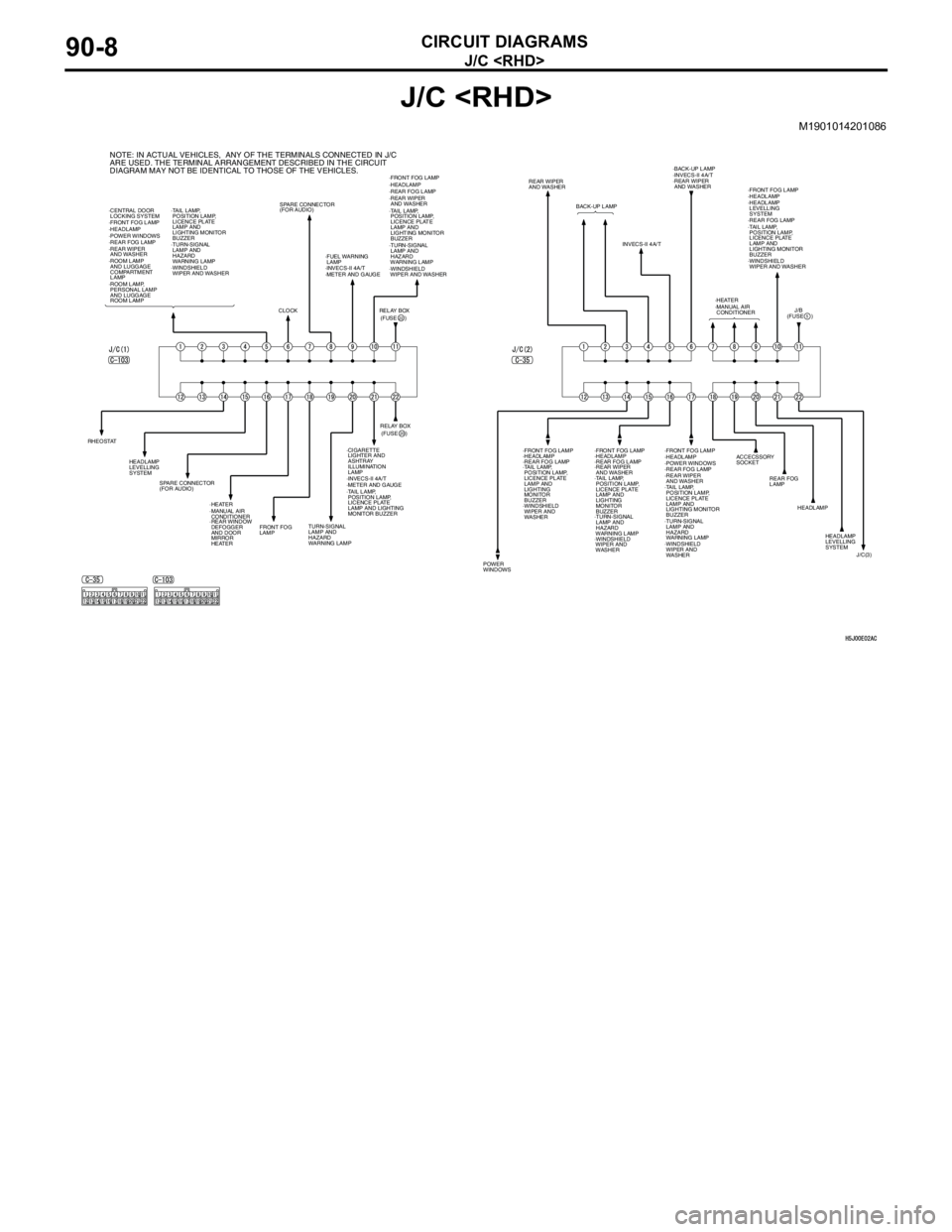
J/C
CIRCUIT DIAGRAMS90-8
J/C
M1901014201086
·ROOM LAMP
AND LUGGAGE
COMPARTMENT
LAMP
·ROOM LAMP,
PERSONAL LAMP
AND LUGGAGE
ROOM LAMP ·CENTRAL DOOR
LOCKING SYSTEM
·FRONT FOG LAMP
·HEADLAMP
·POWER WINDOWS
·REAR FOG LAMP
·REAR WIPER
AND WASHER·TAIL LAMP,
POSITION LAMP,
LICENCE PLATE
LAMP AND
LIGHTING MONITOR
BUZZER
·TURN-SIGNAL
LAMP AND
HAZARD
WARNING LAMP
·WINDSHIELD
WIPER AND WASHER
CLOCKSPARE CONNECTOR
(FOR AUDIO)
·FUEL WARNING
LAMP
·INVECS-II 4A/T
·METER AND GAUGE·FRONT FOG LAMP
·HEADLAMP
·REAR FOG LAMP
·REAR WIPER
AND WASHER
·TAIL LAMP,
POSITION LAMP,
LICENCE PLATE
LAMP AND
LIGHTING MONITOR
BUZZER
·TURN-SIGNAL
LAMP AND
HAZARD
WARNING LAMP
·WINDSHIELD
WIPER AND WASHER
(FUSE ) RELAY BOX
22
RHEOSTAT
·CIGARETTE
LIGHTER AND
ASHTRAY
ILLUMINATION
LAMP HEADLAMP
LEVELLING
SYSTEM
·HEATER
·MANUAL AIR
CONDITIONER SPARE CONNECTOR
(FOR AUDIO)
·REAR WINDOW
DEFOGGER
AND DOOR
MIRROR
HEATERFRONT FOG
LAMPTURN-SIGNAL
LAMP AND
HAZARD
WARNING LAMP ·TAIL LAMP,
POSITION LAMP,
LICENCE PLATE
LAMP AND LIGHTING
MONITOR BUZZER ·INVECS-II 4A/T
·METER AND GAUGE(FUSE ) RELAY BOX20
NOTE: IN ACTUAL VEHICLES, ANY OF THE TERMINALS CONNECTED IN J/C
ARE USED. THE TERMINAL ARRANGEMENT DESCRIBED IN THE CIRCUIT
DIAGRAM MAY NOT BE IDENTICAL TO THOSE OF THE VEHICLES.
REAR WIPER
AND WASHER
BACK-UP LAMP
INVECS-II 4A/T·INVECS-II 4A/T ·BACK-UP LAMP
·REAR WIPER
AND WASHER
·HEATER
·MANUAL AIR
CONDITIONER·FRONT FOG LAMP
·HEADLAMP
·REAR FOG LAMP
·TAIL LAMP,
POSITION LAMP,
LICENCE PLATE
LAMP AND
LIGHTING MONITOR
BUZZER
·WINDSHIELD
WIPER AND WASHER ·HEADLAMP
LEVELLING
SYSTEM
(FUSE )
5
POWER
WINDOWSHEADLAMP
LEVELLING
SYSTEM HEADLAMP
REAR FOG
LAMP ACCECSSORY
SOCKET
·FRONT FOG LAMP
·HEADLAMP
·TAIL LAMP,
POSITION LAMP,
LICENCE PLATE
LAMP AND
LIGHTING
MONITOR
BUZZER
·WINDSHIELD
WIPER AND
WASHER·FRONT FOG LAMP
·HEADLAMP
·REAR FOG LAMP
·REAR WIPER
AND WASHER
·TAIL LAMP,
POSITION LAMP,
LICENCE PLATE
LAMP AND
LIGHTING
MONITOR
BUZZER
·TURN-SIGNAL
LAMP AND
HAZARD
WARNING LAMP
·WINDSHIELD
WIPER AND
WASHER·FRONT FOG LAMP
·HEADLAMP
·POWER WINDOWS
·REAR FOG LAMP
·REAR WIPER
AND WASHER
·TAIL LAMP,
POSITION LAMP,
LICENCE PLATE
LAMP AND
LIGHTING MONITOR
BUZZER
·TURN-SIGNAL
LAMP AND
HAZARD
WARNING LAMP·REAR FOG LAMP
·WINDSHIELD
WIPER AND
WASHERJ/C(3) J/B