rear view mirror MITSUBISHI LANCER 2005 Workshop Manual
[x] Cancel search | Manufacturer: MITSUBISHI, Model Year: 2005, Model line: LANCER, Model: MITSUBISHI LANCER 2005Pages: 788, PDF Size: 45.98 MB
Page 290 of 788

WINDOW GLASS
BODY42-12
WINDSHIELD
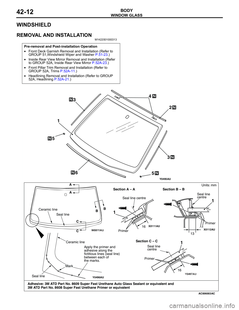
REMOVAL AND INSTALLATIONM1422001000313
Pre-removal and Post-installation Operation
•Front Deck Garnish Removal and Installation (Refer to
GROUP 51,Windshield Wiper and Washer P.51-23.)
•Inside Rear View Mirror Removal and Installation (Refer
to GROUP 52A, Inside Rear View Mirror P.52A-23.)
•Front Pillar Trim Removal and Installation (Refer to
GROUP 52A, Trims P.52A-11.)
•Headlining Removal and Installation (Refer to GROUP
52A, Headlining P.52A-21.)
AC006003
X0111AUX0112AU
Y0496AU
12
3 4
6
1 11 3
N
N
N
N
N
AC Y0495AU
A
A
BB
C
C Ceramic line
Seal line
Seal line
Ceramic line
MarkMark
Apply the primer and
adhesive along the
fictitious lines (seal line)
between each of
the marks.
Seal line centre
Primer Section A – A Section B – BSeal line
centre
Primer
Section C – C
Seal line
centre
Primer
5N
5N
Units: mm
Adhesive: 3M ATD Part No. 8609 Super Fast Urethane Auto Glass Sealant or equivalent and
3M ATD Part No. 8608 Super Fast Urethane Primer or equivalent
16
1613
Page 376 of 788

DOOR MIRROR
EXTERIOR51-38
COMMENTS ON TROUBLE SYMPTOM
The heated door mirrors should works for
approximately 11 minutes when the rear defogger
switch is turned on. If the mirror heater does not work
for the specified period, the defogger relay circuit
(heated door mirror power supply circuit) may be
defective.
Possible causes
•Damaged harness wires and connectors
DIAGNOSIS PROCEDURE
STEP 1. Check the rear window defogger.
Check that the rear window defogger system should
work normally.
Q: Is the check result normal?
YES :
Go to Step 2.
NO : Troubleshoot the rear window defogger
(Refer to GROUP 55,
TroubleshootingP.55-42).
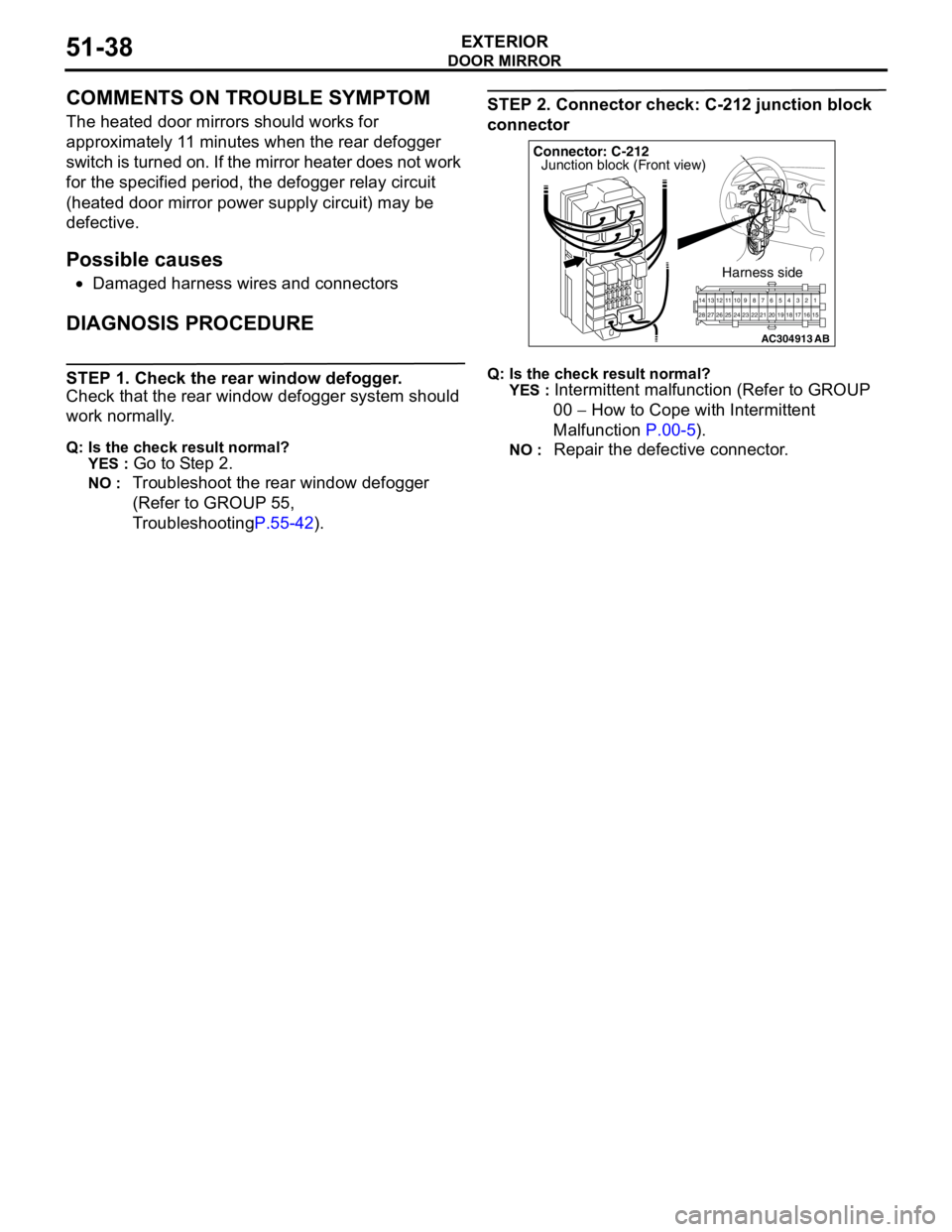
STEP 2. Connector check: C-212 junction block
connector
Q: Is the check result normal?
YES :
Intermittent malfunction (Refer to GROUP
00 − How to Cope with Intermittent
Malfunction P.00-5).
NO : Repair the defective connector.
AC304913
21716151718 201912345 623 222425282627981011141213
Connector: C-212
Harness side
AB
Junction block (Front view)
Page 382 of 788

DOOR MIRROR
EXTERIOR51-44
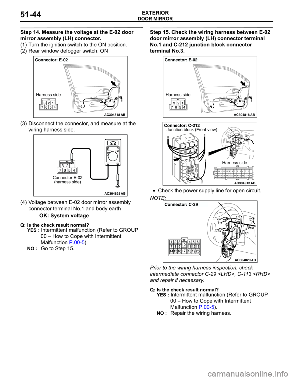
Step 14. Measure the voltage at the E-02 door
mirror assembly (LH) connector.
(1) Turn the ignition switch to the ON position.
(2) Rear window defogger switch: ON
(3) Disconnect the connector, and measure at the
wiring harness side.
(4) Voltage between E-02 door mirror assembly
connector terminal No.1 and body earth
OK: System voltage
Q: Is the check result normal?
YES :
Intermittent malfunction (Refer to GROUP
00 − How to Cope with Intermittent
Malfunction P.00-5).
NO : Go to Step 15.
Step 15. Check the wiring harness between E-02
door mirror assembly (LH) connector terminal
No.1 and C-212 junction block connector
terminal No.3.
•Check the power supply line for open circuit.
NOTE:
Prior to the wiring harness inspection, check
intermediate connector C-29
and repair if necessary.
Q: Is the check result normal?
YES :
Intermittent malfunction (Refer to GROUP
00 − How to Cope with Intermittent
Malfunction P.00-5).
NO : Repair the wiring harness.
AC304818
Connector: E-02
Harness side
AB
AC304828
Connector E-02
(harness side)
AB
AC304818
Connector: E-02
Harness side
AB
AC304913
21716151718 201912345 623 222425282627981011141213
Connector: C-212
Harness side
AB
Junction block (Front view)
AC304820
Connector: C-29
AB