width MITSUBISHI LANCER 2005 Workshop Manual
[x] Cancel search | Manufacturer: MITSUBISHI, Model Year: 2005, Model line: LANCER, Model: MITSUBISHI LANCER 2005Pages: 788, PDF Size: 45.98 MB
Page 135 of 788

SERVICE SPECIFICATIONS
FRONT AXLE26-3
SERVICE SPECIFICATIONS
M1261000300396
LUBRICANTS
M1261000400382
Item Standard value Limit
Wheel bearing axial play mm
−0.05
Hub starting torque N⋅m
−1.8
Protruding length of stabilizer bar mounting bolt mm 22 ± 1.5
−
Setting of TJ boot length mm 1.3L-RH, 1.6L-A/T-RH 85 ± 3
−
1.3L-LH, 1.6L-M/T,
1.6L-A/T-LH, 2.0L90 ± 3
−
Opening dimension of the
special tool (MB991561) mmWhen the BJ boot band
(small) is crimped2.9
−
When the BJ boot band
(large) is crimped2.9
−
Crimped width of the BJ boot band mm 2.4 − 2.8
−
Item Specified lubricant Quantity
TJ boot grease Repair kit grease 1.3L-LH, 1.6L-LH, 2.0L-LH 120 ± 10 g
1.3L-RH, 1.6L-A/T-RH 110 ± 10 g
1.6L-M/T-RH 120 ± 10 g
2.0L-RH 105 ± 10 g
BJ boot grease Repair kit grease 95 ± 10 g
Page 240 of 788

SERVICE SPECIFICATIONS
POWER STEERING37-6
SERVICE SPECIFICATIONS
M1372000300386
Item Standard value Limit
Steering wheel free
play mmWith engine running
−30
With engine stopped 10 or less
−
Steering angle Inner wheel Comfort 39°30' ± 1°30'
−
Sport (L.H. drive vehicles) 33°40' +1°00'/-2°00'
−
Sport (R.H. drive vehicles) 37°00' +1°00'/-2°00'
−
Outer wheel
(reference)Comfort 32°30'
−
Sport (L.H. drive vehicles) 28°46'
−
Sport (R.H. drive vehicles) 30°00'
−
Toe-in At the centre of tyre tread mm 1 ± 2
−
Toe-angle (per wheel) 0°03' ± 06'
−
Tie rod end ball joint turning torque N⋅m0.5 − 2.5
−
Tie rod swing resistance N [Tie rod swing torque N⋅m] 8 − 27 [1.5 − 4.9]
−
Stationary steering effort N [Fluctuation allowance N] 29 or less [5.9 or less]
−
Oil pump pressure
MPa (750 ± 100 r/min.)Oil pump relief pressure 8.8 − 9.5
−
Pressure under no-load conditions 0.2 − 0.7
−
Steering gear retention hydraulic pressure 8.8 − 9.5
−
Oil pressure switch operating pressure
MPaOFF → ON 1.5 − 2.0
−
ON → OFF 0.7 − 2.0
−
Steering gear total pinion torque N⋅m
[Change in torque N⋅m]1300, 1600 (Comfort) 0.8 − 2.1 [0.6 or less]
−
1600 (Sport), 2000 0.7 − 2.1 [0.6 or less]
−
Opening dimension of special tool boot band crimping tool (MB991561)
mm2.9
−
Band crimped width mm 2.4 − 2.8
−
Page 269 of 788
POWER STEERING GEAR BOX AND LINKAGE
POWER STEERING37-35
CAUTION
When adjusting, set at the highest value of the
standard value range.
NOTE: If the total pinion toque cannot be adjusted
to the standard value within the specified return
angle, check the rack support cover components
and replace any parts if necessary.
2. If the total pinion torque or the change in torque is
outside the standard value, move the rack support
cover 0 − 30°, and adjust the pinion torque again.
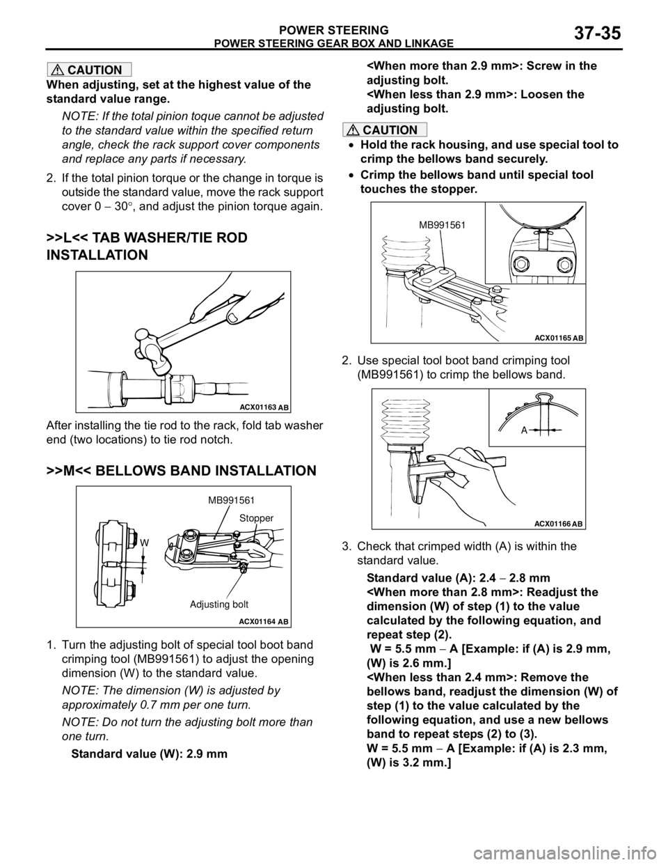
>>L<< TAB WASHER/TIE ROD
INSTALLATION
After installing the tie rod to the rack, fold tab washer
end (two locations) to tie rod notch.
>>M<< BELLOWS BAND INSTALLATION
1. Turn the adjusting bolt of special tool boot band
crimping tool (MB991561) to adjust the opening
dimension (W) to the standard value.
NOTE: The dimension (W) is adjusted by
approximately 0.7 mm per one turn.
NOTE: Do not turn the adjusting bolt more than
one turn.
Standard value (W): 2.9 mm
adjusting bolt.
adjusting bolt.
CAUTION
•Hold the rack housing, and use special tool to
crimp the bellows band securely.
•Crimp the bellows band until special tool
touches the stopper.
2. Use special tool boot band crimping tool
(MB991561) to crimp the bellows band.
3. Check that crimped width (A) is within the
standard value.
Standard value (A): 2.4 − 2.8 mm
dimension (W) of step (1) to the value
calculated by the following equation, and
repeat step (2).
W = 5.5 mm − A [Example: if (A) is 2.9 mm,
(W) is 2.6 mm.]
bellows band, readjust the dimension (W) of
step (1) to the value calculated by the
following equation, and use a new bellows
band to repeat steps (2) to (3).
W = 5.5 mm − A [Example: if (A) is 2.3 mm,
(W) is 3.2 mm.]
ACX01163
AB
ACX01164
AB
WMB991561
Adjusting boltStopper
ACX01165AB
MB991561
ACX01166
AB
A
Page 275 of 788
POWER STEERING OIL PUMP ASSEMBLY
POWER STEERING37-41
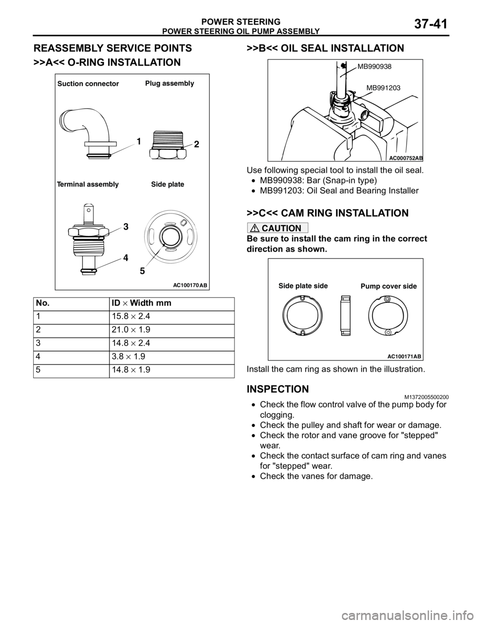
REASSEMBLY SERVICE POINTS
>>A<< O-RING INSTALLATION>>B<< OIL SEAL INSTALLATION
Use following special tool to install the oil seal.
•MB990938: Bar (Snap-in type)
•MB991203: Oil Seal and Bearing Installer
>>C<< CAM RING INSTALLATION
CAUTION
Be sure to install the cam ring in the correct
direction as shown.
Install the cam ring as shown in the illustration.
INSPECTIONM1372005500200
•Check the flow control valve of the pump body for
clogging.
•Check the pulley and shaft for wear or damage.
•Check the rotor and vane groove for "stepped"
wear.
•Check the contact surface of cam ring and vanes
for "stepped" wear.
•Check the vanes for damage. No. ID × Width mm
1 15.8 × 2.4
2 21.0 × 1.9
3 14.8 × 2.4
43.8 × 1.9
5 14.8 × 1.9
AC100170
AB
Suction connectorPlug assembly
Terminal assembly Side plate
1
2
3
4
5
AC000752
MB990938
AB
MB991203
AC100171AB
Side plate side
Pump cover side
Page 340 of 788
FRONT BUMPER ASSEMBLY
EXTERIOR51-2
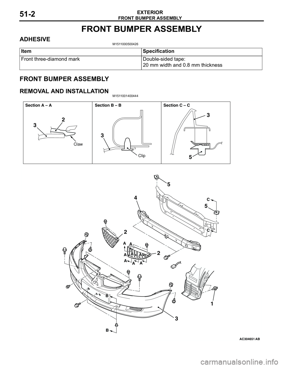
FRONT BUMPER ASSEMBLY
ADHESIVEM1511000500426
FRONT BUMPER ASSEMBLY
REMOVAL AND INSTALLATIONM1511001400444
Item Specification
Front three-diamond mark Double-sided tape:
20 mm width and 0.8 mm thickness
AC304651AB
32
3
5
2
2 45
5
31
3
C
C
B
BA
A
A A A
A
AA
Claw
Clip Section A – A Section B – B Section C – C
Page 341 of 788
FRONT BUMPER ASSEMBLY
EXTERIOR51-3
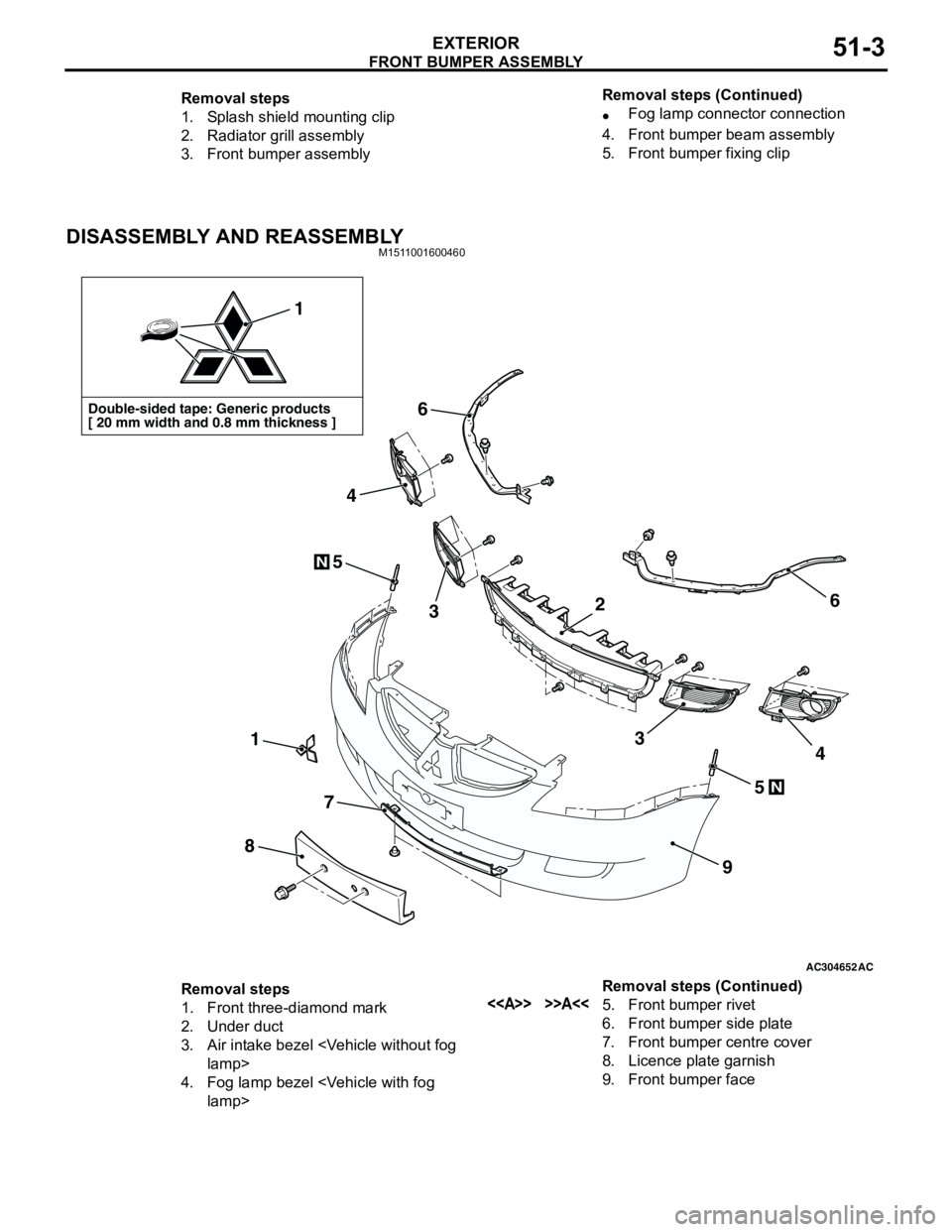
DISASSEMBLY AND REASSEMBLYM1511001600460
Removal steps
1. Splash shield mounting clip
2. Radiator grill assembly
3. Front bumper assembly•Fog lamp connector connection
4. Front bumper beam assembly
5. Front bumper fixing clip Removal steps (Continued)
AC304652AC
Double-sided tape: Generic products
[ 20 mm width and 0.8 mm thickness ]
1
1
8
7
9
6
6
5
5
3
4
34
N
N
2
Removal steps
1. Front three-diamond mark
2. Under duct
3. Air intake bezel
4. Fog lamp bezel
6. Front bumper side plate
7. Front bumper centre cover
8. Licence plate garnish
9. Front bumper face Removal steps (Continued)
Page 347 of 788
MOULDINGS
EXTERIOR51-9
MOULDINGS
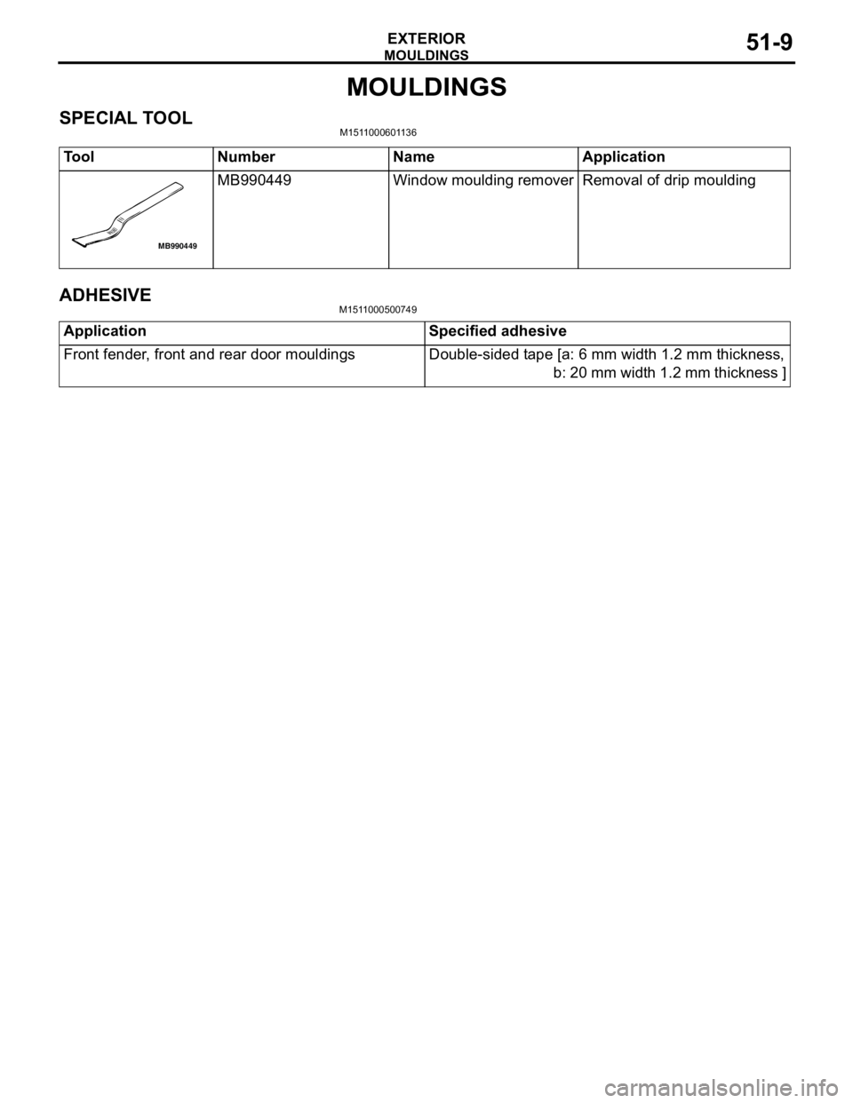
SPECIAL TOOLM1511000601136
ADHESIVEM1511000500749
Tool Number Name Application
MB990449 Window moulding remover Removal of drip moulding
MB990449
Application Specified adhesive
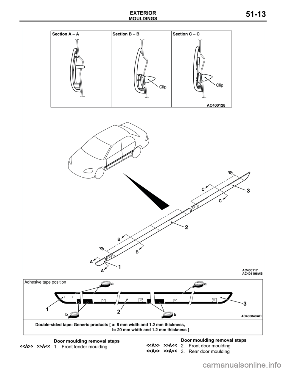
Front fender, front and rear door mouldings Double-sided tape [a: 6 mm width 1.2 mm thickness,
b: 20 mm width 1.2 mm thickness ]
Page 351 of 788
MOULDINGS
EXTERIOR51-13
AC401196 AC400117
AC400128
Section A – A Section B – B Section C – C
AB
A
AB
BC
C
2
1
3
ClipClip
AC400840AD
Double-sided tape: Generic products [ a: 6 mm width and 1.2 mm thickness,
b: 20 mm width and 1.2 mm thickness ]
12
3
a
b baAdhesive tape position
Door moulding removal steps
<> >>A<<1. Front fender mouldingDoor moulding removal steps<> >>A<<2. Front door moulding
<> >>A<<3. Rear door moulding
Page 353 of 788
SIDE AIR DAM
EXTERIOR51-15
SIDE AIR DAM
ADHESIVEM1511000500437
SIDE AIR DAM
REMOVAL AND INSTALLATIONM1511005500238
Item Specification
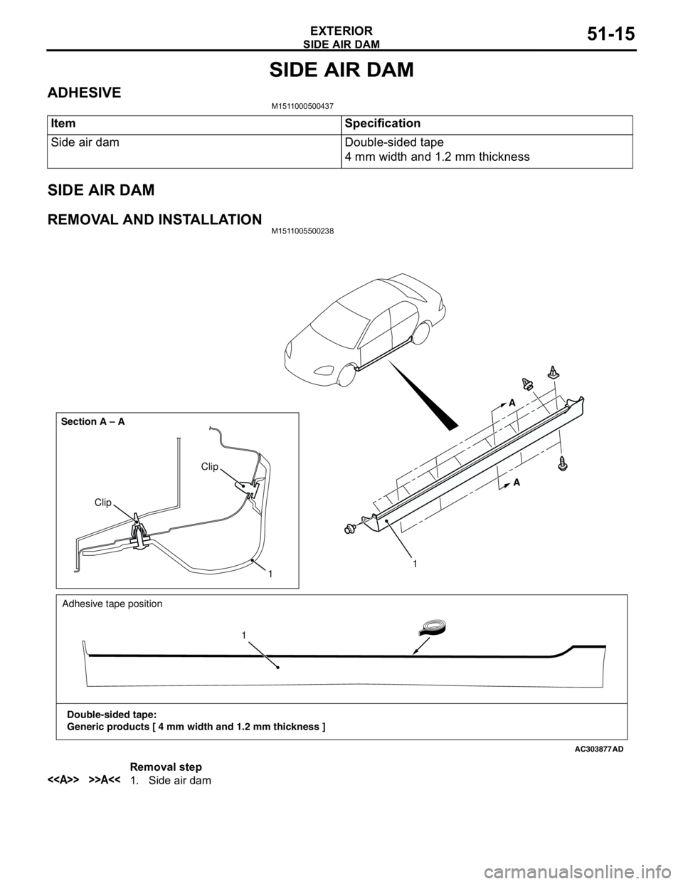
Side air dam Double-sided tape
4 mm width and 1.2 mm thickness
AC303877
Clip
Clip Section A – A
AD
1
A A
Adhesive tape position
Double-sided tape:
Generic products [ 4 mm width and 1.2 mm thickness ]11
Removal step
<> >>A<<1. Side air dam