body MITSUBISHI LANCER 2006 Owners Manual
[x] Cancel search | Manufacturer: MITSUBISHI, Model Year: 2006, Model line: LANCER, Model: MITSUBISHI LANCER 2006Pages: 800, PDF Size: 45.03 MB
Page 331 of 800
KEYLESS ENTRY SYSTEM
BODY42-59
REASSEMBLY SERVICE POINT
>>A<< BATTERY INSTALLATION
CAUTION
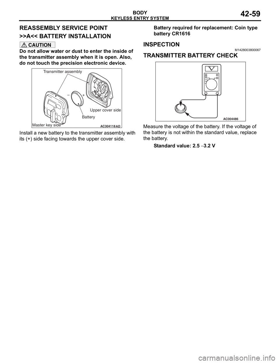
Do not allow water or dust to enter the inside of
the transmitter assembly when it is open. Also,
do not touch the precision electronic device.
AC304118AD
+
–
Master key side Upper cover side
Battery
Transmitter assembly
Install a new battery to the transmitter assembly with
its (+) side facing towards the upper cover side.
Battery required for replacement: Coin type
battery CR1616
INSPECTION
M1428003800067
TRANSMITTER BATTERY CHECK
AC004486
Measure the voltage of the battery. If the voltage of
the battery is not within the standard value, replace
the battery.
Standard value: 2.5 − 3.2 V
Page 343 of 800
MOULDINGS
EXTERIOR51-11
INSTALLATION SERVICE POINTS
>>A<< DRIP MOULDING CLIP C/DRIP
MOULDING CLIP B/DRIP MOULDING
CLIP A INSTALLATION
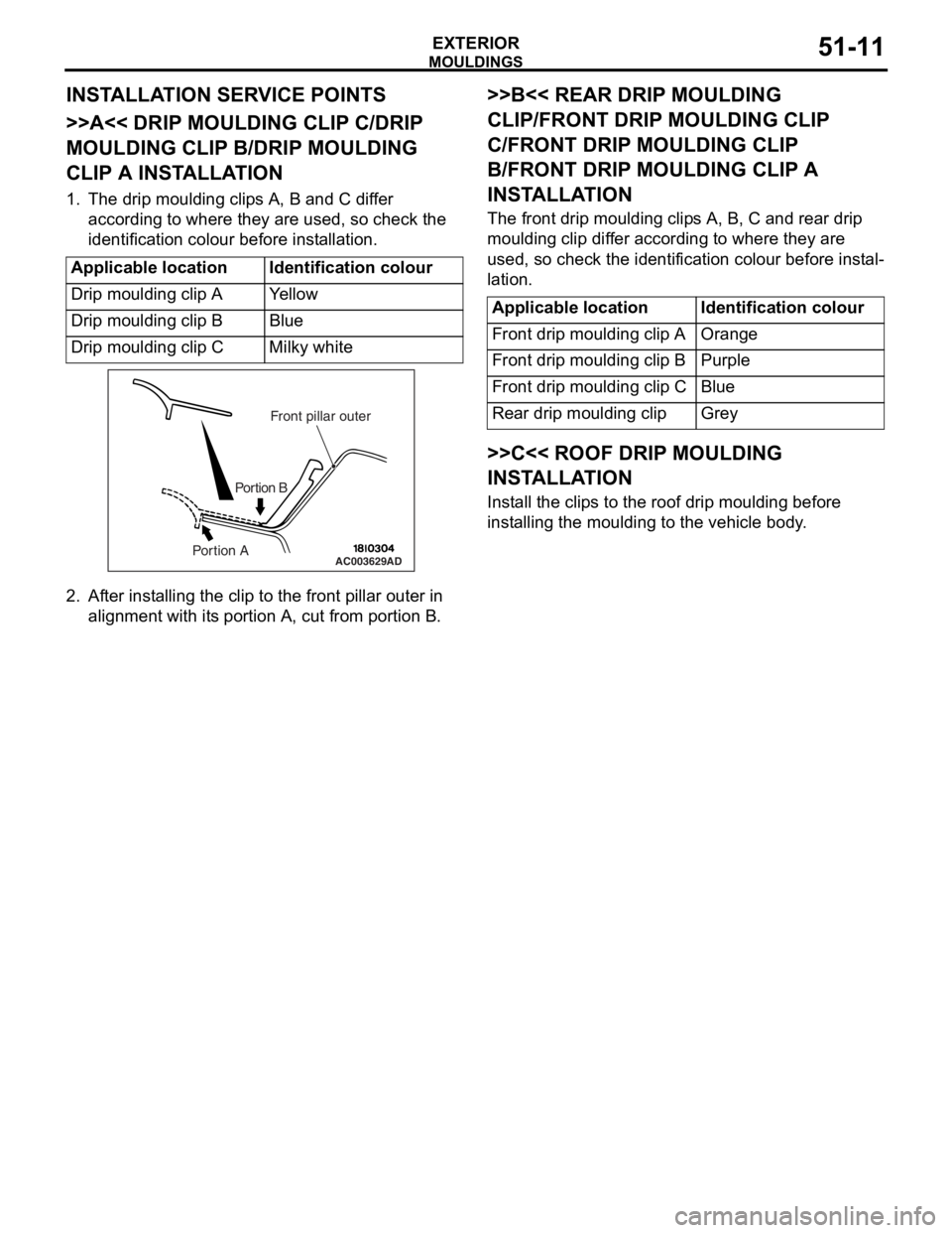
1. The drip moulding clips A, B and C differ according to where they are used, so check the
identification colour before installation.
Applicable locationIdentification colour
Drip moulding clip AYe l l o w
Drip moulding clip BBlue
Drip moulding clip CMilky white
AC003629
Front pillar outer
Portion B
Portion AAD
2. Af ter inst alling the clip to the f r ont pilla r outer in
align m ent with it s portio n A, cu t from portion B.
>>B<< REAR DRIP MOULDING
CLIP/FRONT DRIP MOULDING CLIP
C/FRONT DRIP MOULDING CLIP
B/FRONT DRIP MOULDING CLIP A
INST
ALLA TION
The front drip mou l din g clip s A, B, C an d rear d r ip
moulding
clip dif f er accordin g to where they are
used
, so check th e ide n tification colou r before inst al
-
lation.
Applicable locationIdentification colour
Front drip moulding clip AOrange
Front drip moulding clip BPurple
Front drip moulding clip CBlue
Rear drip moulding clipGrey
>>C<< ROOF DRIP MOULDING
INSTALLA TION
Install the clip s to th e roof d r ip mould i ng before
inst
allin g the moulding to the vehicle body .
Page 345 of 800
AC000420Double-sided tapeProtection tapeAB
MO
UL DI N G S
EXTERIOR51-13
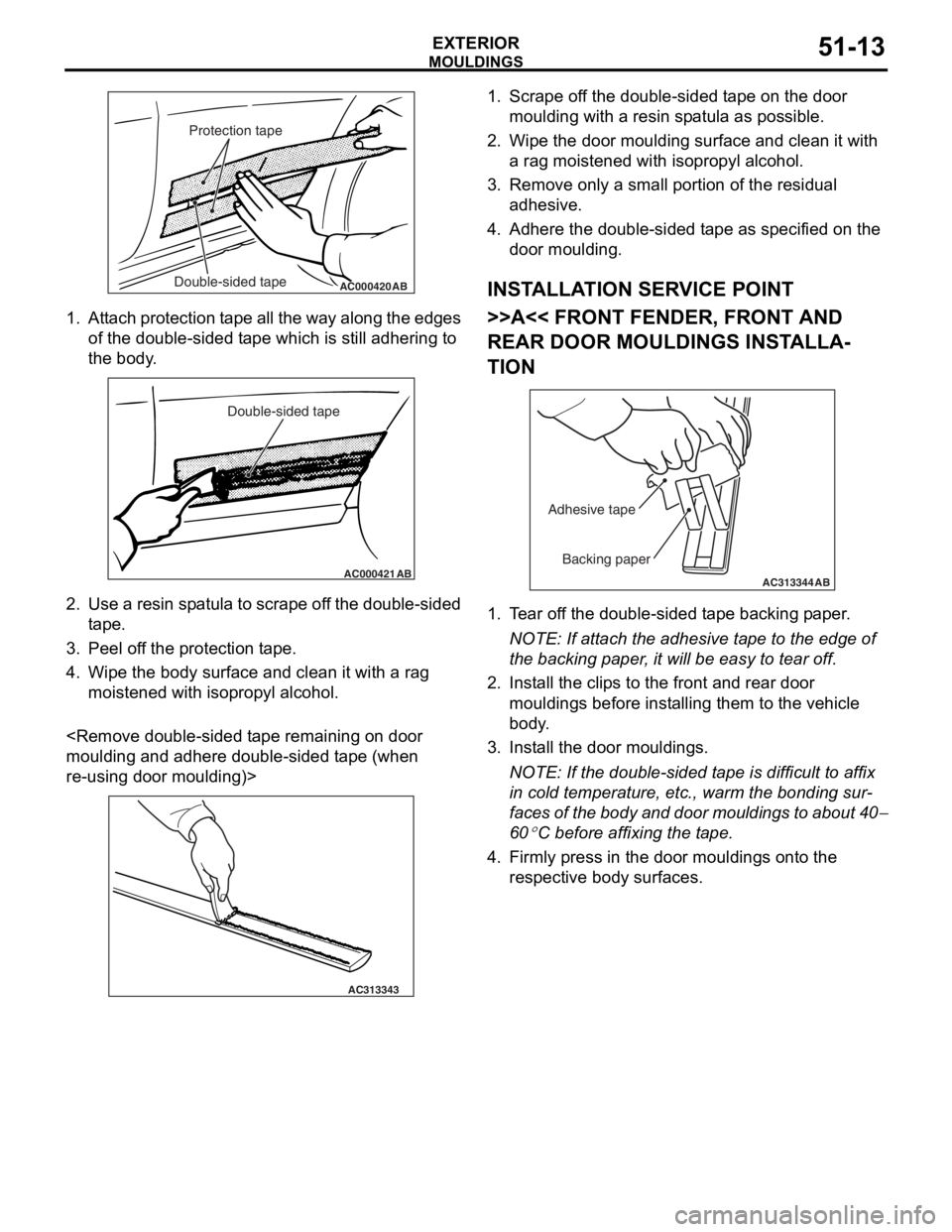
1.At t a ch pro t ection t a pe all th e wa y alon g the e dge s
of the do uble - sid ed t ape which is still adh ering to
th e body .
AC000421
Double-sided tape
AB
2.Use a resin sp atula to scrape of f t he dou ble-sided
t ape .
3.Pee l of f the pr otect i on t ape .
4.Wipe th e body su rface and clean it with a rag
moistened with isopro p yl alcohol.
and a dhere d ouble-sided t ape (wh en
re-using do
or mo ulding)>
AC313343
1.Scrape o f f the double-sided t ape on th e door
moulding with a re sin sp atula as possible.
2.Wipe th e door moulding surfa c e a nd clean it with
a rag moistened with isoprop yl a l co hol.
3.Remove only a small po rtion o f the re sid ual
a dhesive .
4.Adh e re the double-sided t ape as specified on t he
d oor mo ulding.
INSTALLA T ION SER VICE POINT
>>A<< FRONT FENDER, FRONT AND
REAR DOOR MOULDINGS INST
ALLA
-
TION
AC313344
Backing paper
Adhesive tape
AB
1.
T ear of f the double-sided t ape backing p aper .
NOTE: If atta ch the adhesive t a pe to the edg e of
th
e backing p aper , it will be easy to te ar off.
2.In st all the clip s to the front a nd rear door
mouldings befo r e inst alling th em to the vehicle
b ody .
3.In st all the do or mo uldings.
NOTE: If the double-sided t ape is difficult to af fix
in co
ld te mpera t ure, et c., warm the b ondin g su r
-
faces of the bod y and doo r mo uldin g s to ab out 40−
60
°C bef ore affixing the t a p e .
4.Firmly pre ss in the door moulding s ont o the
re spective bod y surface s .
Page 347 of 800
Page 374 of 800
AC304163
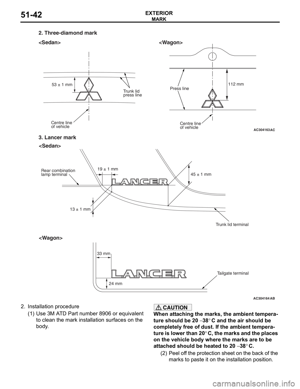
2. Three-diamond mark
Centre line
of vehicleCentre line
of vehicle
Trunk lid
press linePress line
112 mm
53 ± 1 mm
AC
AC304164
3. Lancer mark
Rear combination
lamp terminal
Trunk lid terminalTailgate terminal
33 mm 24 mm 45 ± 1 mm
13 ± 1 mm 19 ± 1 mm
AB
MARK
EXTERIOR51-42
2.
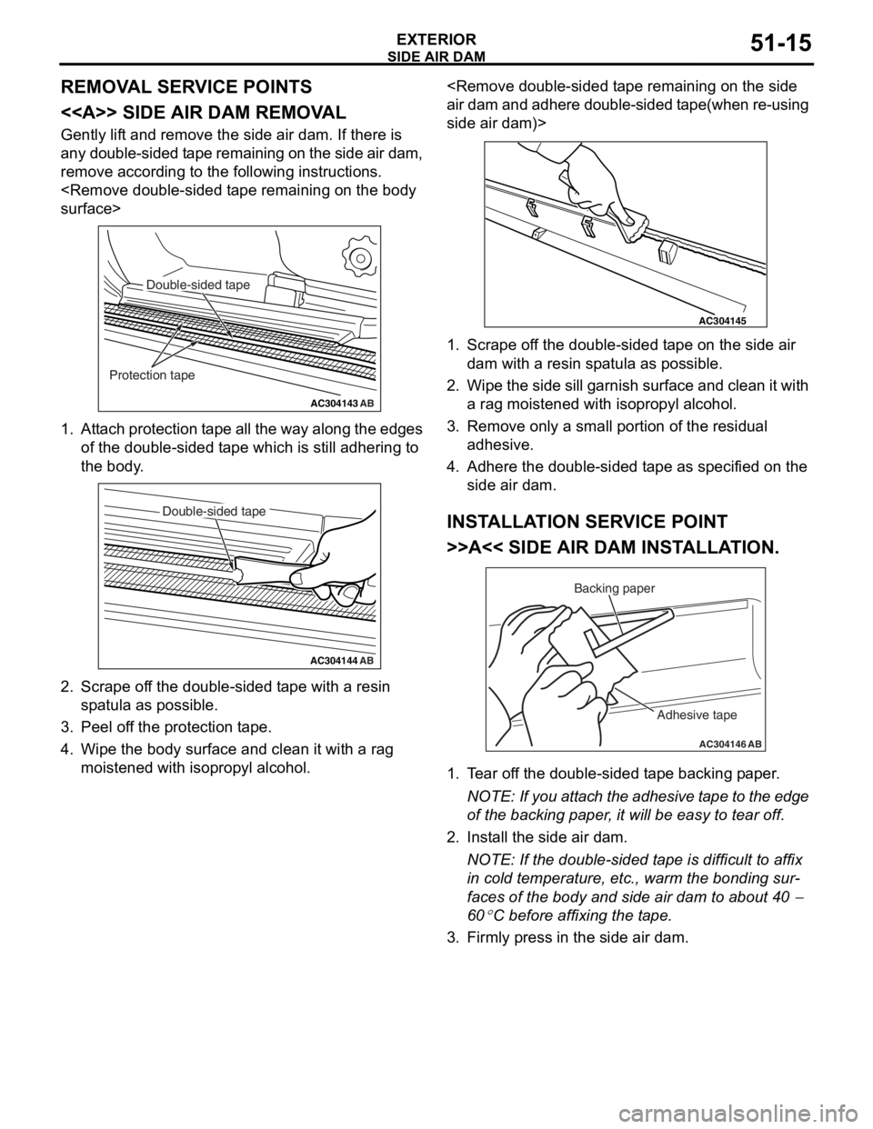
In st allation procedure
(1)U se 3 M A T D Pa rt number 890 6 or eq uivalen t
to clean the mark inst allation surface s on the
body .
CAUTION
When attaching the marks, the ambient tempera-
ture should be 20 − 38°C and the air should be
completely free of dust. If the ambient tempera
-
ture is lower than 20°C, the marks and the places
on the vehicle body where the marks are to be
attached should be heated to 20
− 38°C.
(2) Peel off the protection sheet on the back of the marks to paste it on the installation position.
Page 382 of 800
DOOR MIRROR
EXTERIOR51-50
DOOR MIRROR
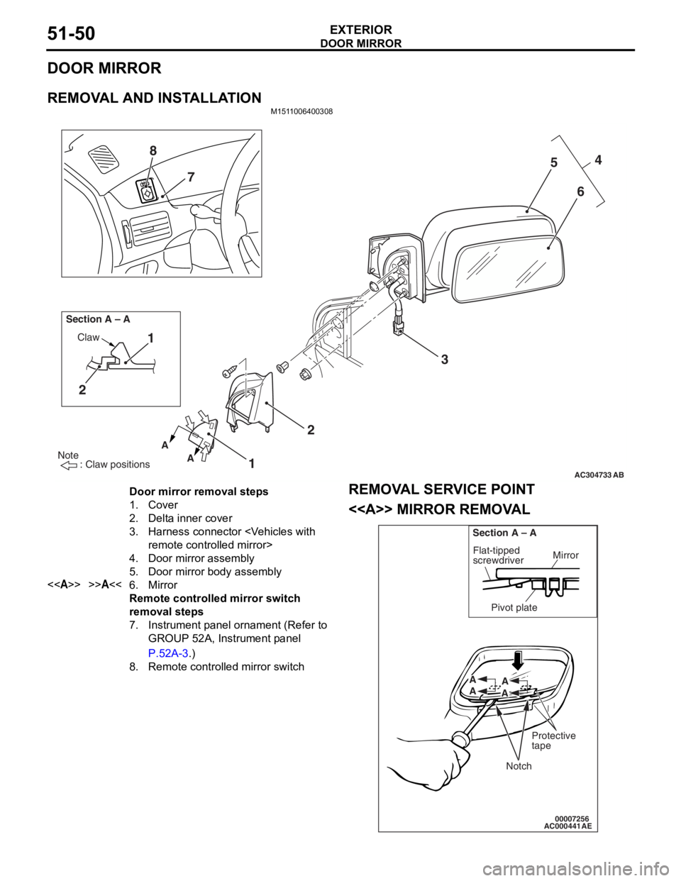
REMOVAL AND INSTALLATION
M1511006400308
AC304733
Note
: Claw positions
AB
AA
Section A – A
Claw1
2
12 3 4
5
6
7
8
Door mirror removal steps
1.Cover
2.Delta inner cover
3.Harness connector
4.Door mirror assembly
5.Door mirror body assembly
<>>>A<<6.Mirror
Remote controlled mirror switch
removal steps
7.Instrument panel ornament (Refer to
GROUP 52A, Instrument panel
P.52A-3.)
8.Remote controlled mirror switch
REMOV
A L SER VICE POINT
<> MIRROR REMOV A L
AC00044100007256
Mirror
Flat-tipped
screwdriver
Section A – A
Pivot plate
Notch
Protective
tape
A
A A
A
AE
Page 396 of 800
SENSOR
COMPONENT LOCATIONS70-6
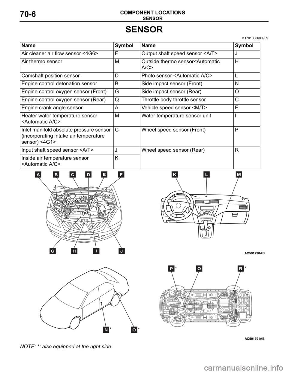
SENSOR
M1701000600909
NameSymbolNameSymbol
Air cleaner air flow sensor <4G6>FOutput shaft speed sensor J
Air thermo sensorMOutside thermo sensor
Camshaft position sensorDPhoto sensor
Engine control detonation sensorBSide impact sensor (Front)N
Engine control oxygen sensor (Front)GSide impact sensor (Rear)O
Engine control oxygen sensor (Rear)QThrottle body throttle sensorC
Engine crank angle sensorAVehicle speed sensor
Heater water temperature sensor
Inlet manifold absolute pressure sensor
(incorporating intake air temperature
sensor) <4G1>CWheel speed sensor (Front)P
Input shaft speed sensor JWheel speed sensor (Rear)R
Inside air temperature sensor
AC501790
BDCFEA
GHIJ
MKL
AB
AC501791AB
NO
POR
** *
*
NO
TE: *: also eq uipp ed at t he rig h t side.
Page 397 of 800
AC208762
A
AD
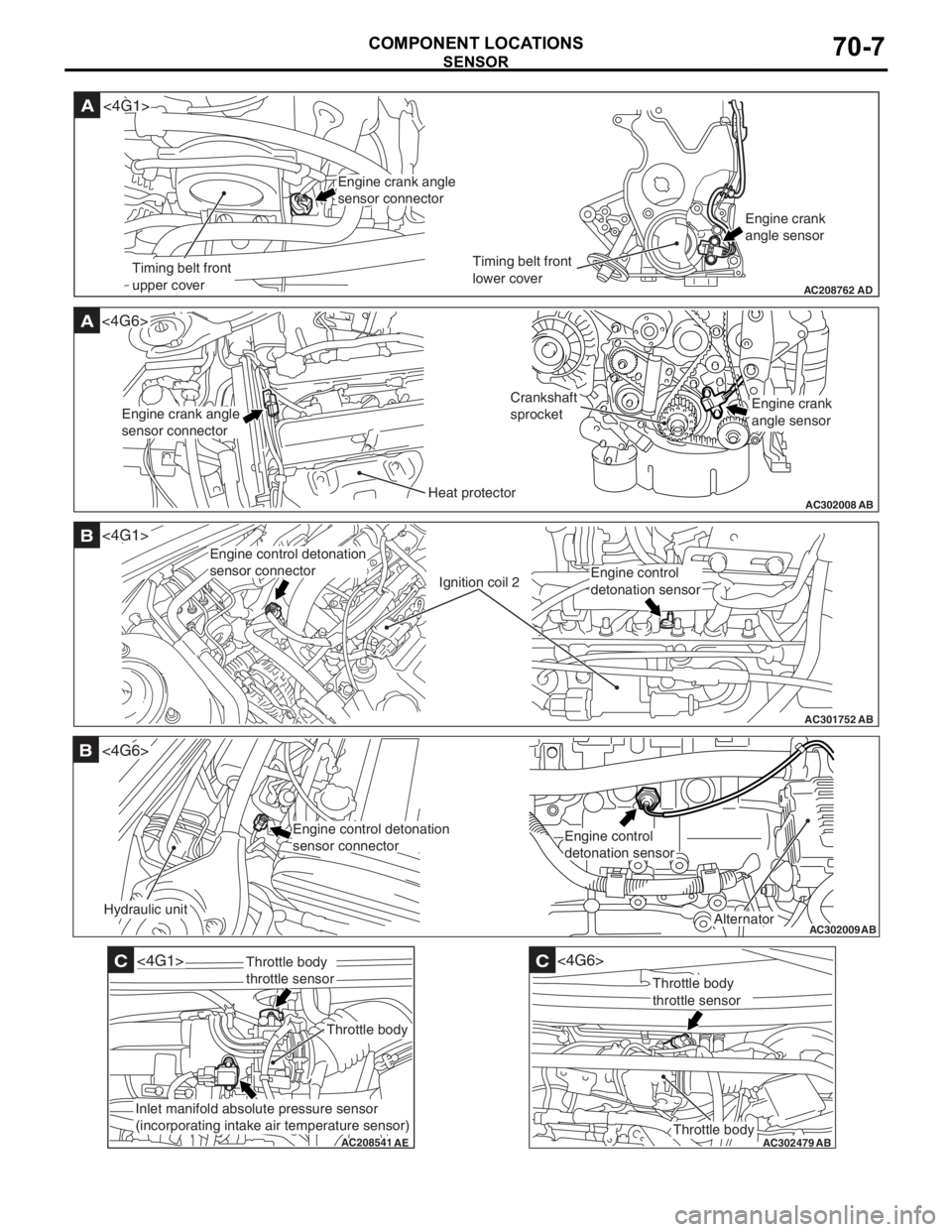
Timing belt front
upper coverTiming belt front
lower coverEngine crank
angle sensor
<4G1>
Engine crank angle
sensor connector
AC302008
A<4G6>
ABHeat protector
Crankshaft
sprocket
Engine crank angle
sensor connectorEngine crank
angle sensor
AC301752
B
AB
Ignition coil 2
<4G1>
Engine control detonation
sensor connector
Engine control
detonation sensor
AC302009
B
AB
Hydraulic unit
<4G6>
Alternator
Engine control detonation
sensor connectorEngine control
detonation sensor
AC208541
C
AE
<4G1>
Throttle body
Throttle body
throttle sensor
Inlet manifold absolute pressure sensor
(incorporating intake air temperature sensor)
AC302479
AB
C
Throttle body
<4G6>
Throttle body
throttle sensor
SENSOR
COMPONENT LOCA TIONS70-7
Page 402 of 800
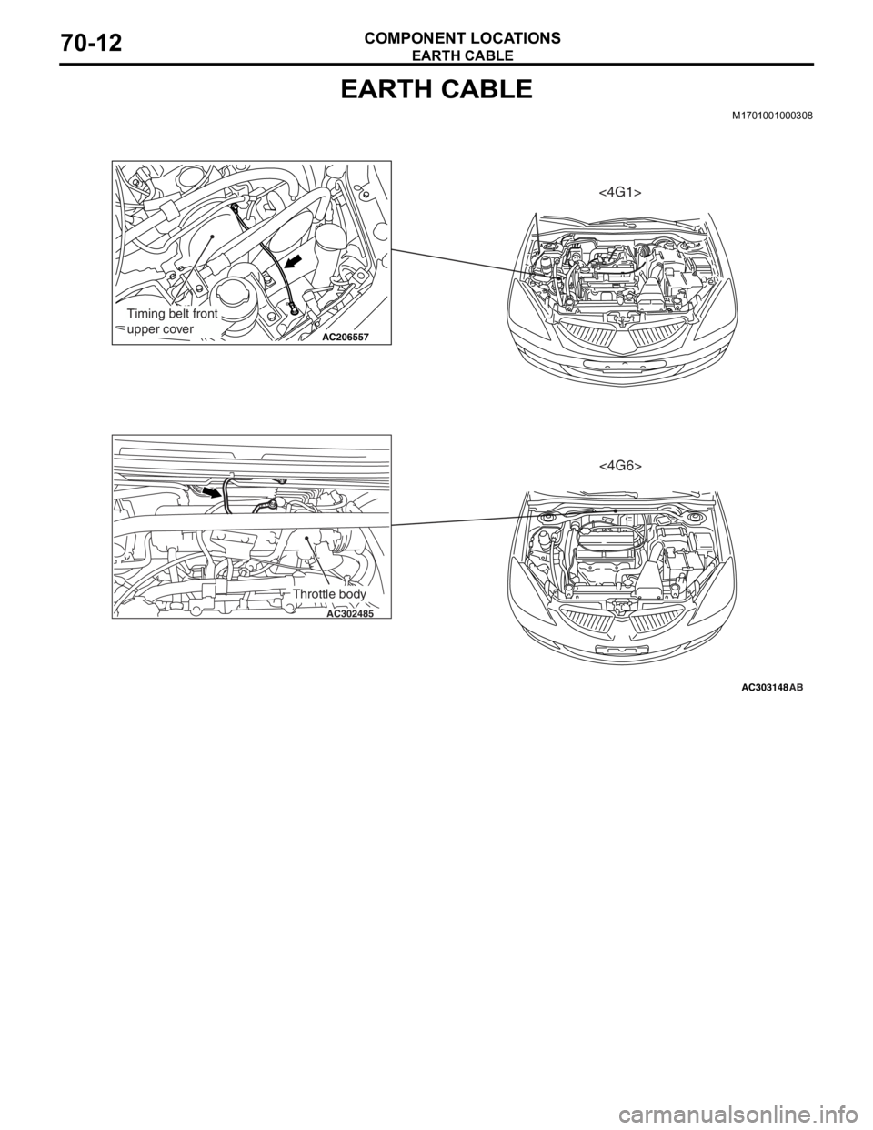
EARTH CABLE
COMPONENT LOCATIONS70-12
EARTH CABLE
M1701001000308
AC303148
AC206557
AC302485
AB
Timing belt front
upper cover
Throttle body
<4G1><4G6>
Page 420 of 800
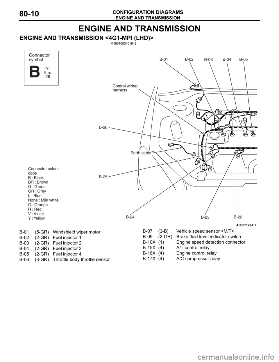
ENGINE AND TRANSMISSION
CONFIGURATION DIAGRAMS80-10
ENGINE AND TRANSMISSION
ENGINE AND TRANSMISSION <4G1-MPI (LHD)>M1801000401949
AC301129
AD
B-02
B-03B-04B-05
B-22
B-23
B-24
B-25
B-26
Control wiring
harnessB-01
Connector colour
code
B : Black
BR : Brown
G : Green
GR : Grey
L : Blue
None : Milk white
O : Orange
R : Red
V : Violet
Y : Yellow*
Connector
symbol
-01
thru
-26
B
Earth cable
B-01(5-GR)Windshield wiper motor
B-02(2-GR)Fuel injector 1
B-03(2-GR)Fuel injector 2
B-04(2-GR)Fuel injector 3
B-05(2-GR)Fuel injector 4
B-06(3-GR)Throttle body throttle sensor
B-07(3-B)Vehicle speed sensor
B-09(2-GR)Brake fluid level indicator switch
B-10X(1)Engine speed detection connector
B-15X(4)A/T control relay
B-16X(4)Engine control relay
B-17X(4)A/C compressor relay