service MITSUBISHI LANCER 2006 Workshop Manual
[x] Cancel search | Manufacturer: MITSUBISHI, Model Year: 2006, Model line: LANCER, Model: MITSUBISHI LANCER 2006Pages: 800, PDF Size: 45.03 MB
Page 313 of 800
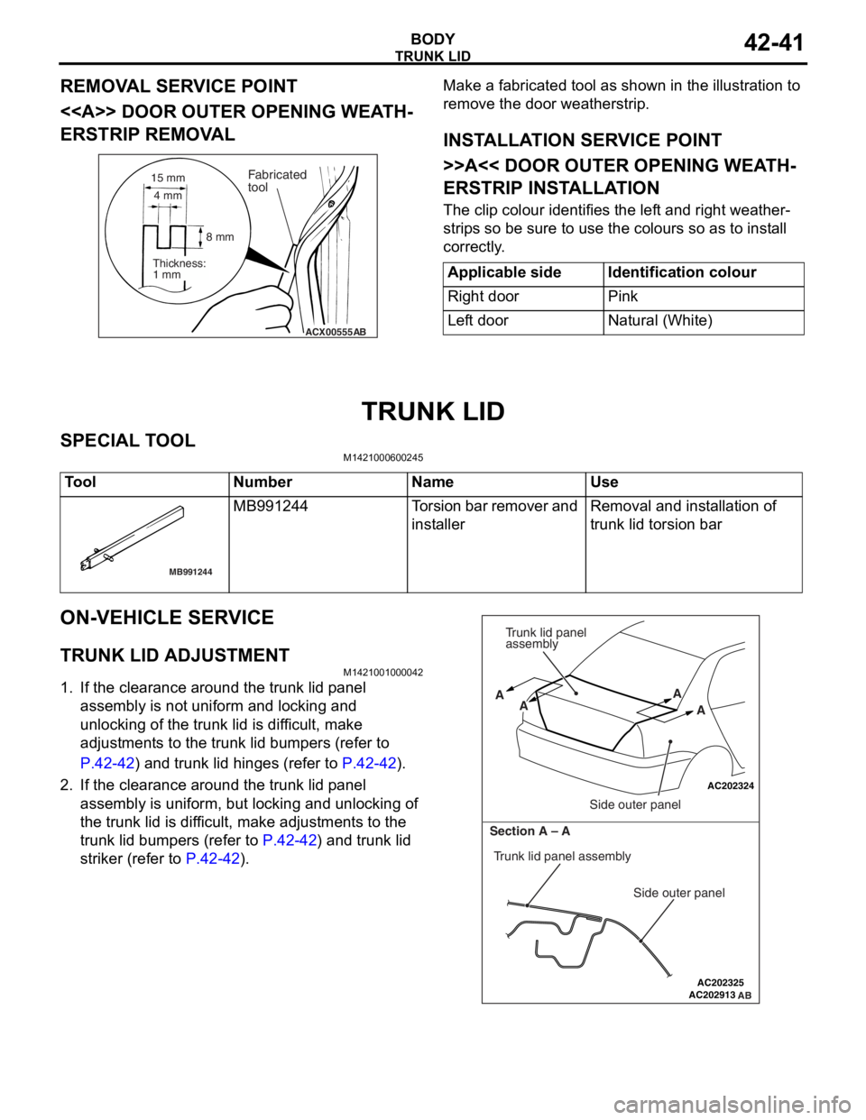
Page 318 of 800
TAILGATE
BODY42-46
TA I L G AT E
SERVICE SPECIFICATIONSM1421000300288
ItemStandard value
Tailgate handle play (mm)2.3 − 5.9
SEALANTS
M1424000500098
ItemSpecified sealant
Tailgate waterproof film3M ATD Part No.8633 or equivalent
Tailgate hinge3M ATD Part No.8531 Heavy drip check sealer, 3M
ATD Part No.8646 Automotive joint and seam sealer
or equivalent
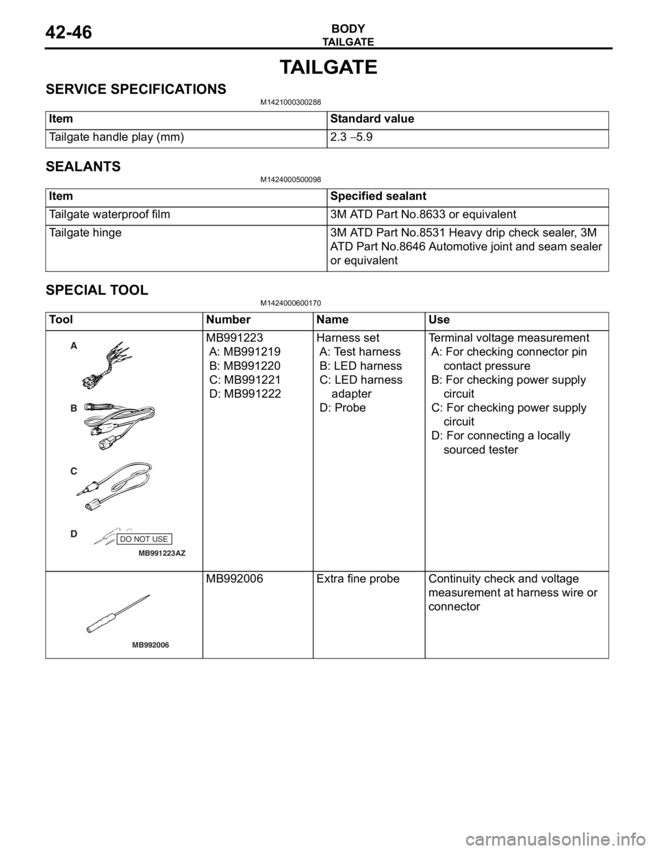
SPECIAL TOOLM1424000600170
ToolNumberNameUse
MB991223
A
D C
B
AZ
DO NOT USE
MB991223
A: MB9912 19
B: MB991220
C: MB99122 1
D: MB991222
Harness set
A: Te st harn e ss
B: LED harness
C: LED harness
adapt er
D: Probe
Te rminal volt a ge measu r emen t
A: For che cking connector pin
cont act pressure
B: For che cking po we r sup p ly
circuit
C: Fo r checking po we r supp ly
circuit
D: Fo r conn ecting a loca lly
sourced tester
MB992006
MB992 006Extra fine probeCont inuity check an d vo lt age
measurement at
harness wire or
conn
ector
Page 319 of 800
TAILGATE
BODY42-47
TROUBLESHOOTING
M1424000700207
The tailgate system is controlled by the Smart Wiring
System (SWS). For troubleshooting, refer to GROUP
54B, Troubleshooting
P.54B-15 or GROUP 54C,
Troubleshooting P.54C-4.
ON-VEHICLE SERVICE
TAILGATE FIT ADJUSTMENTM1424000900137
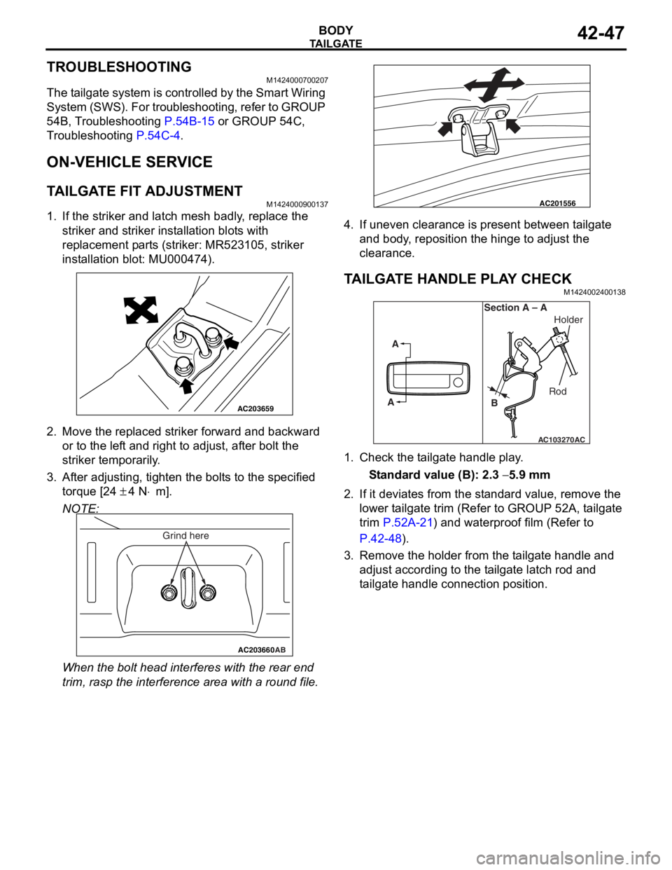
1. If the striker and latch mesh badly, replace the striker and striker installation blots with
replacement parts (striker: MR523105, striker
installation blot: MU000474).
AC203659
2.Move the rep l aced strike r forward a nd backward
or to the lef t and right to adjust, af te r bolt the
striker temporarily .
3.Af ter ad justing, tighte n the bolt s t o the specifie d
to rque [2 4
± 4 N⋅m].
NOTE:
AC203660AB
Grind here
When the bolt head interfe r es wit h the re ar end
trim, ra
sp th e int e rference are a with a round file .
AC201556
4.If uneven clearan ce is pre s en t between t a ilga te
a nd bod y , reposition the hing e to ad just the
clear ance .
TA ILGA TE HANDLE PLA Y CHECKM14240024 0013 8
AC103270
A
A Section A – A
RodHolder
B
AC
1. Check t he t a ilgate h andle play .
St andard va lue (B): 2.3 − 5.9 mm
2.If it de via t es fro m the st anda rd va lue, r e move the
lower t a ilgate trim (Refe r to GROUP 52A, t a ilgate
trim
P.52A-21) and waterproo f film (Refer to
P.42-48).
3.Remove the ho lder f r om th e t a ilg ate ha ndle and
a d just according to the t a ilgate latch rod an d
t a ilgate handle co nnection position .
Page 325 of 800
KEYLESS ENTRY SYSTEM
BODY42-53
TROUBLESHOOTING
M1428000700287
The keyless entry system is controlled by the Smart
Wiring System (SWS). For troubleshooting, refer to
GROUP 54B, Troubleshooting
P.54B-15 or GROUP
54C, Troubleshooting P.54C-4.
ON-VEHICLE SERVICE
KEYLESS ENTR Y SYSTEM CHECKM1428001400096
Check the system as described below. If the system
does not work, carry out troubleshooting. Refer to
GROUP 54B, Troubleshooting
P.54B-15, refer to
GROUP 54C, Troubleshooting P.54C-4.
•Operate the transmitter to check that the doors
and tailgate can be locked and unlocked.
•Operate the transmitter to check that the answer-
back function works in response to door and tail-
gate
NOTE: The adjustment function allows you to
change the answerback setting as follows. Prior
to that check, confirm which setting is activated.
.
•The hazard warning lamps flash twice when
locked and once when unlocked. The room
lamp flashes twice when locked and illumi
-
nates for 15 seconds when unlocked.
•The hazard warning lamps do not flash when
locked and flash once when unlocked. The
room lamp flashes twice when locked and illu
-
minates for 15 seconds when unlocked.
•The hazard warning lamps flash twice when
locked and do not flash when unlocked. The
room lamp flashes twice when locked and illu
-
minates for 15 seconds when unlocked.
•The hazard warning lamps do not flash when
both locked and unlocked. The room lamp
flashes twice when locked and illuminates for
15 seconds when unlocked.
KEYLESS ENTRY SYS TEM TIMER LOCK
FUNCTION INSPECTION
M1428004000138
Push the transmitter unlock button and check to see
that the doors and tailgate
seconds. If it doesn't, then execute troubleshooting
remedies. Refer to GROUP 54B, Troubleshooting
P.54B-15, refer to GROUP 54C, Troubleshooting
P.54C-4.
ENABLING/DISABLING THE
ANSWERBACK FUNCTION
M1428003200214
If the keyless entry system locks or unlocks the
doors, the room lamp flashes or illuminates, the haz
-
ard warning lamp flashes (hazard answerback func-
tion). The hazard answerback function can be
enabled or disabled according to the following proce
-
dure:
ENABLING/DISABLING THE HAZARD
ANSWERBACK FUNCTION
The hazard answerback function can be enabled or
disabled by one of the two following procedures.
1. Enter the hazard answerback customize mode by performing one of the following steps. If the
ETACS-ECU enters the customize mode, its
buzzer will sound once.
(1) Turn the ignition switch to “LOCK”(OFF) position.
(2) Turn off the hazard warning lamp switch.
CAUTION
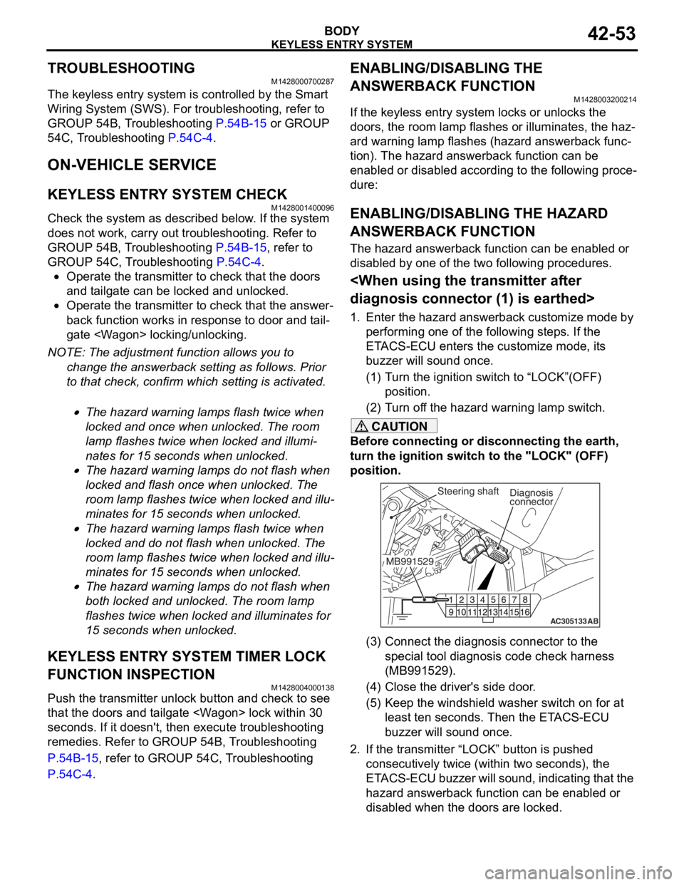
Before connecting or disconnecting the earth,
turn the ignition switch to the "LOCK" (OFF)
position.
AC305133AB
Diagnosis
connector
MB991529Steering shaft
(3) Connect the diagnosis connector to the special tool diagnosis code check harness
(MB991529).
(4) Close the driver's side door.
(5) Keep the windshield washer switch on for at least ten seconds. Then the ETACS-ECU
buzzer will sound once.
2. If the transmitter “LOCK” button is pushed consecutively twice (wit hin two seconds), the
ETACS-ECU buzzer will sound, indicating that the
hazard answerback function can be enabled or
disabled when the doors are locked.
Page 331 of 800
KEYLESS ENTRY SYSTEM
BODY42-59
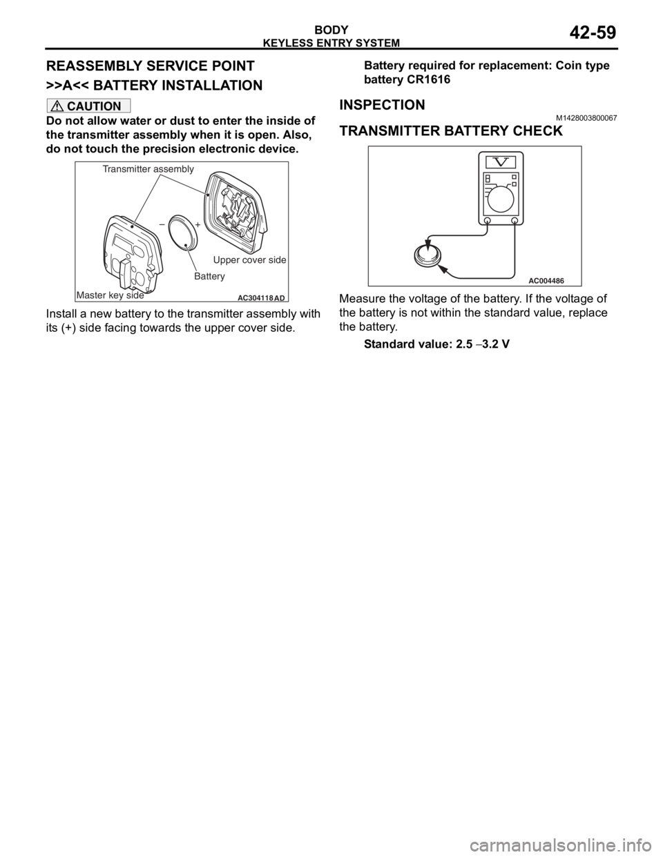
REASSEMBLY SERVICE POINT
>>A<< BATTERY INSTALLATION
CAUTION
Do not allow water or dust to enter the inside of
the transmitter assembly when it is open. Also,
do not touch the precision electronic device.
AC304118AD
+
–
Master key side Upper cover side
Battery
Transmitter assembly
Install a new battery to the transmitter assembly with
its (+) side facing towards the upper cover side.
Battery required for replacement: Coin type
battery CR1616
INSPECTION
M1428003800067
TRANSMITTER BATTERY CHECK
AC004486
Measure the voltage of the battery. If the voltage of
the battery is not within the standard value, replace
the battery.
Standard value: 2.5 − 3.2 V
Page 333 of 800
51-1
GROUP 51
EXTERIOR
CONTENTS
FRONT BUMPER ASSEMBLY . . . . .51-3
ADHESIVE . . . . . . . . . . . . . . . . . . . . . . . . . 51-3
FRONT BUMPER ASSEMBLY . . . . . . . . . . 51-3
REMOVAL AND INSTALLATION . . . . . . . . 51-3
DISASSEMBLY AND REASSEMBLY . . . . . 51-4
REAR BUMPER ASSEMBLY . . . . . .51-6
REMOVAL AND INSTALLATION . . . . . . . . 51-6
DISASSEMBLY AND REASSEMBLY . . . . . 51-7
MOULDINGS . . . . . . . . . . . . . . . . . . .51-8
SPECIAL TOOL . . . . . . . . . . . . . . . . . . . . . 51-8
ADHESIVE . . . . . . . . . . . . . . . . . . . . . . . . . 51-9
MOULDINGS . . . . . . . . . . . . . . . . . . . . . . . 51-9
REMOVAL AND INSTALLATION . . . . . . . . 51-9
SIDE AIR DAM . . . . . . . . . . . . . . . . . .51-14
ADHESIVE . . . . . . . . . . . . . . . . . . . . . . . . . 51-14
SIDE AIR DAM . . . . . . . . . . . . . . . . . . . . . . 51-14
REMOVAL AND INSTALLATION . . . . . . . . 51-14
GARNISHES . . . . . . . . . . . . . . . . . . .51-16
REMOVAL AND INSTALLATION . . . . . . . . 51-16
DOOR SASH TAPE . . . . . . . . . . . . . .51-17
SPECIAL TOOL . . . . . . . . . . . . . . . . . . . . . 51-17
DOOR SASH TAPE . . . . . . . . . . . . . . . . . . 51-17
REMOVAL AND INSTALLATION
REMOVAL AND INSTALLATION
REAR SPOILER
REMOVAL AND INSTALLATION . . . . . . . . 51-25
TAILGATE SPOILER
REMOVAL AND INSTALLATION . . . . . . . . 51-26
ROOF RAIL
REMOVAL AND INSTALLATION . . . . . . . . 51-27
WINDSHIELD WIPER AND
WASHER. . . . . . . . . . . . . . . . . . . . . . .51-28
GENERAL INFORMATION . . . . . . . . . . . . . 51-28
SERVICE SPECIFICATION . . . . . . . . . . . . 51-28
SPECIAL TOOLS . . . . . . . . . . . . . . . . . . . . 51-29
TROUBLESHOOTING . . . . . . . . . . . . . . . . 51-30
ON-VEHICLE SERVICE . . . . . . . . . . . . . . . 51-30
WINDSHIELD WIPER AND WASHER . . . . 51-31
REMOVAL AND INSTALLATION . . . . . . . . 51-31
INSPECTION. . . . . . . . . . . . . . . . . . . . . . . . 51-33
REAR WIPER AND WASHER
GENERAL INFORMATION . . . . . . . . . . . . . 51-35
SERVICE SPECIFICATION . . . . . . . . . . . . 51-35
TROUBLESHOOTING . . . . . . . . . . . . . . . . 51-36
ON-VEHICLE SERVICE . . . . . . . . . . . . . . . 51-36
REAR WIPER AND WASHER . . . . . . . . . . 51-36
REMOVAL AND INSTALLATION . . . . . . . . 51-36
INSPECTION. . . . . . . . . . . . . . . . . . . . . . . . 51-37
Continued on next page
Page 334 of 800
51-2
HEADLAMP WASHER
TROUBLESHOOTING . . . . . . . . . . . . . . . . 51-39
HEADLAMP WASHER . . . . . . . . . . . . . . . . 51-39
REMOVAL AND INSTALLATION . . . . . . . . 51-39
INSPECTION . . . . . . . . . . . . . . . . . . . . . . . 51-40
MARK . . . . . . . . . . . . . . . . . . . . . . . . .51-41
REMOVAL AND INSTALLATION . . . . . . . . 51-41
DOOR MIRROR . . . . . . . . . . . . . . . . .51-43
GENERAL INFORMATION . . . . . . . . . . . . . 51-43
SERVICE SPECIFICATION . . . . . . . . . . . . 51-43
SPECIAL TOOL. . . . . . . . . . . . . . . . . . . . . . 51-43
TROUBLESHOOTING . . . . . . . . . . . . . . . . 51-43
DIAGNOSIS TROUBLESHOOTING FLOW 51-43
TROUBLE SYMPTOM CHART . . . . . . . . . . 51-43
SYMPTOM PROCEDURES . . . . . . . . . . . . 51-44
DOOR MIRROR . . . . . . . . . . . . . . . . . . . . . 51-50
REMOVAL AND INSTALLATION . . . . . . . . 51-50
INSPECTION. . . . . . . . . . . . . . . . . . . . . . . . 51-51
Page 337 of 800

Page 340 of 800
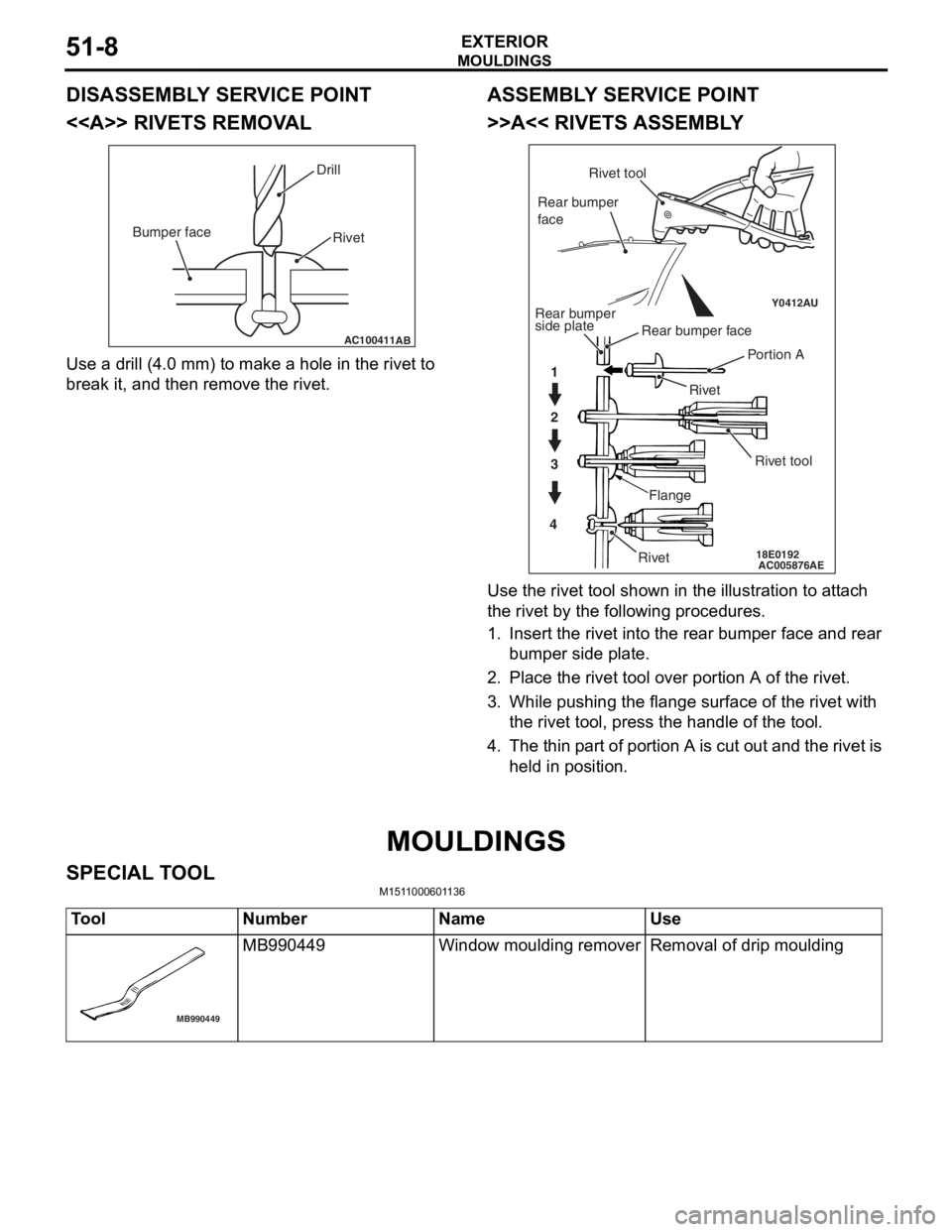
Page 343 of 800
MOULDINGS
EXTERIOR51-11
INSTALLATION SERVICE POINTS
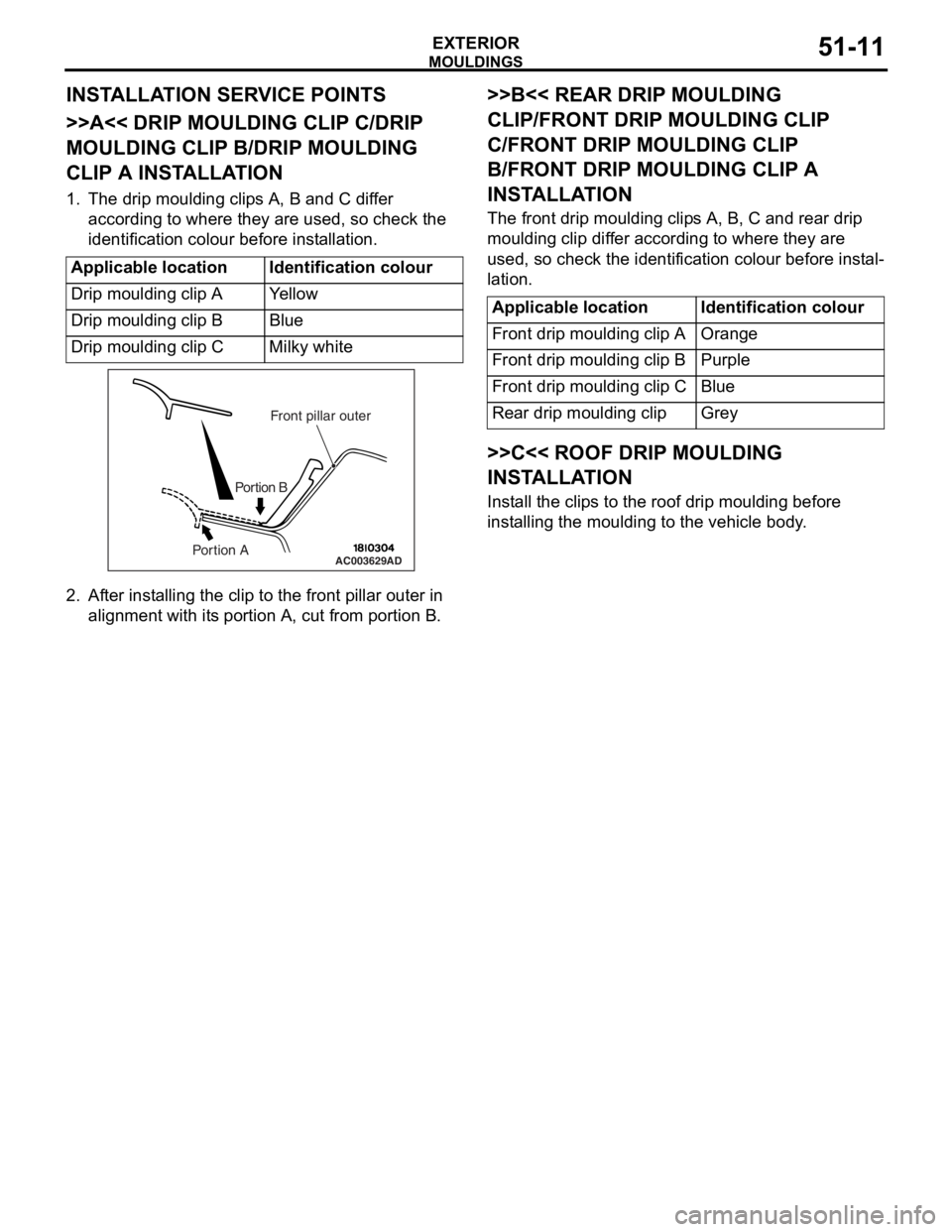
>>A<< DRIP MOULDING CLIP C/DRIP
MOULDING CLIP B/DRIP MOULDING
CLIP A INSTALLATION
1. The drip moulding clips A, B and C differ according to where they are used, so check the
identification colour before installation.
Applicable locationIdentification colour
Drip moulding clip AYe l l o w
Drip moulding clip BBlue
Drip moulding clip CMilky white
AC003629
Front pillar outer
Portion B
Portion AAD
2. Af ter inst alling the clip to the f r ont pilla r outer in
align m ent with it s portio n A, cu t from portion B.
>>B<< REAR DRIP MOULDING
CLIP/FRONT DRIP MOULDING CLIP
C/FRONT DRIP MOULDING CLIP
B/FRONT DRIP MOULDING CLIP A
INST
ALLA TION
The front drip mou l din g clip s A, B, C an d rear d r ip
moulding
clip dif f er accordin g to where they are
used
, so check th e ide n tification colou r before inst al
-
lation.
Applicable locationIdentification colour
Front drip moulding clip AOrange
Front drip moulding clip BPurple
Front drip moulding clip CBlue
Rear drip moulding clipGrey
>>C<< ROOF DRIP MOULDING
INSTALLA TION
Install the clip s to th e roof d r ip mould i ng before
inst
allin g the moulding to the vehicle body .