service MITSUBISHI LANCER 2006 Workshop Manual
[x] Cancel search | Manufacturer: MITSUBISHI, Model Year: 2006, Model line: LANCER, Model: MITSUBISHI LANCER 2006Pages: 800, PDF Size: 45.03 MB
Page 347 of 800
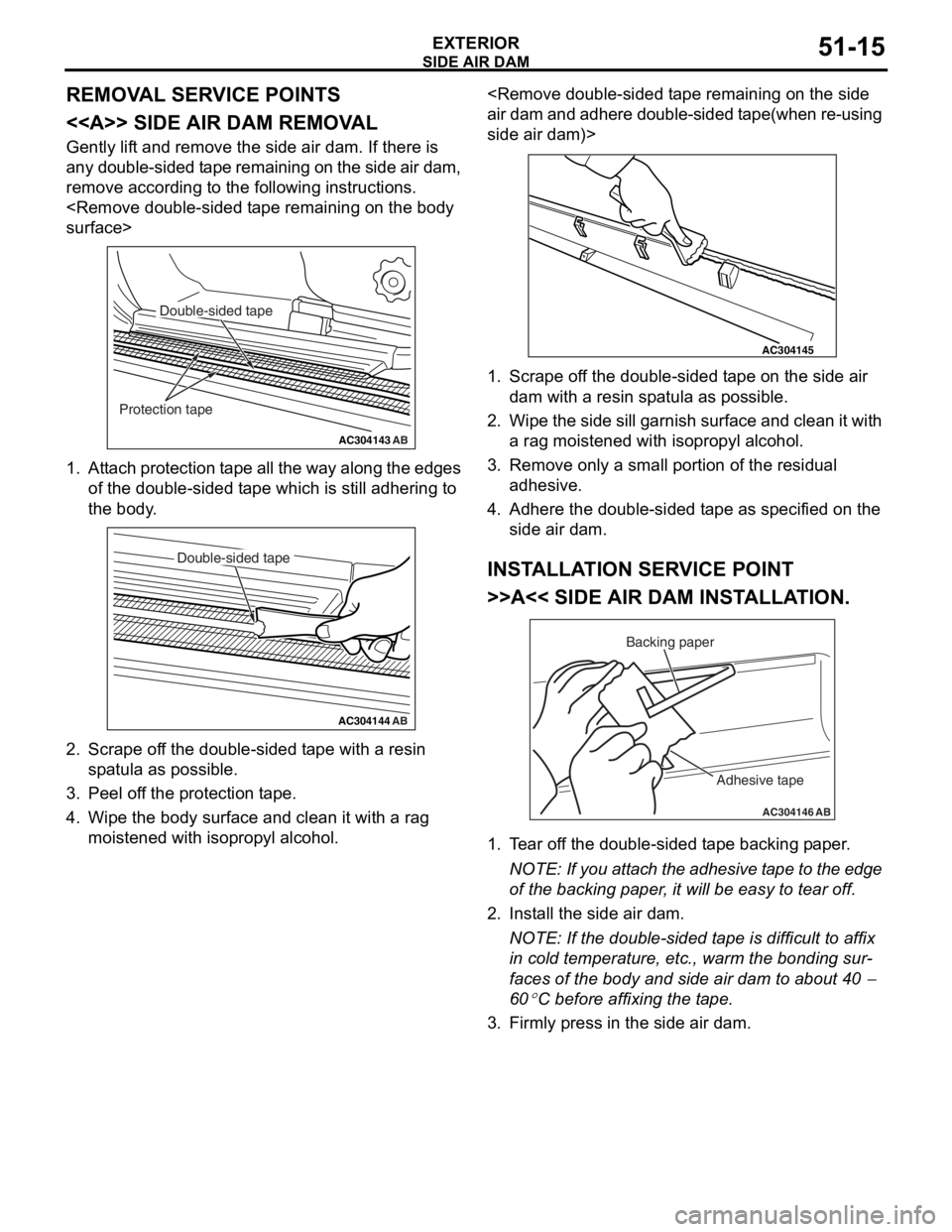
Page 350 of 800
DOOR SASH TAPE
EXTERIOR51-18
INSTALLATION SERVICE POINT
>>A<< DOOR SASH TAPES INSTALLA-
TION
CAUTION
•The ambient temperature should be 20 to
30
°C. Ensure that the working area is clean.
Ideally, the tape application should be done at
ambient temperature of 25
°C.
•If ambient temperature is less than 15°C, heat
the tape and application surface to a tempera
-
ture of 20 to 30°C. If ambient temperature is
35
°C or higher, cool down them. The adhe-
sive property of the tape is deteriorated at low
temperature, so the tape may come adrift eas
-
ily. Meanwhile, it gets softened at hot temper-
ature.
•When beginning to apply the tape, pay partic-
ular attention. If the end of the tape cannot be
applied to the specified position with an accu
-
racy of less than 1 mm, it may cause the poor
appearance or adhesion.
•
AC303428
40 to 50˚
30 to 45˚
10 to 20 mm
10 to 20 mm
AB
MB990528
MB990528 Door sash tapeDoor sash tape
Backing paper
Backing paper
3 to 7 cm/sec.
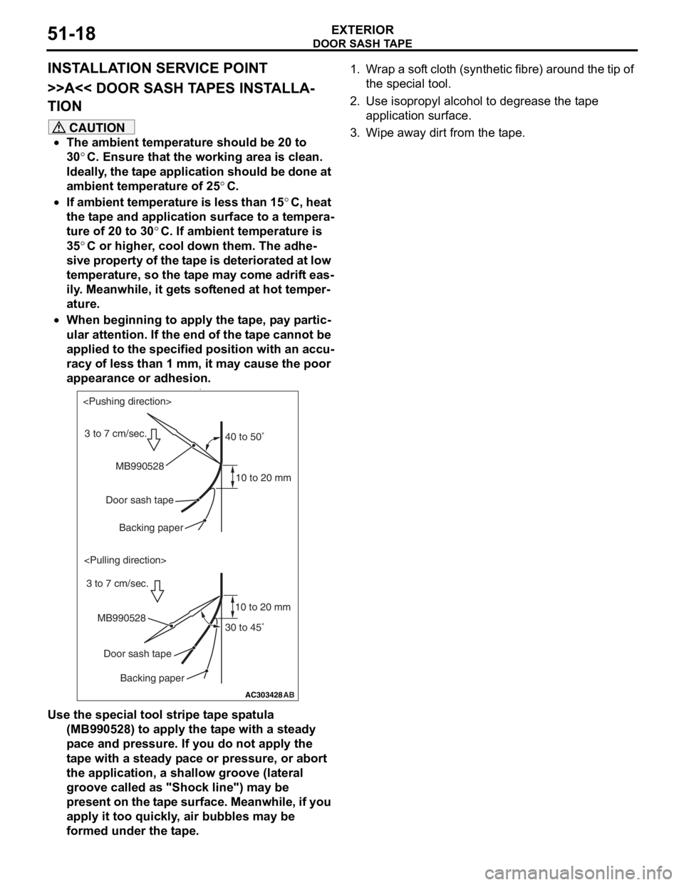
Use the special tool stripe tape spatula (MB990528) to apply the tape with a steady
pace and pressure. If you do not apply the
tape with a steady pace or pressure, or abort
the application, a shallow groove (lateral
groove called as "Shock line") may be
present on the tape surface. Meanwhile, if you
apply it too quickly, air bubbles may be
formed under the tape.
1. Wrap a soft cloth (synthetic fibre) around the tip of
the special tool.
2. Use isopropyl alcohol to degrease the tape application surface.
3. Wipe away dirt from the tape.
Page 354 of 800
DOOR SASH TAPE
EXTERIOR51-22
INSTALLATION SERVICE POINT
>>A<< DOOR SASH TAPES INSTALLA-
TION
CAUTION
•The ambient temperature should be 20 to
30
°C. Ensure that the working area is clean.
Ideally, the tape application should be done at
ambient temperature of 25
°C.
•If ambient temperature is less than 15°C, heat
the tape and application surface to a tempera
-
ture of 20 to 30°C. If ambient temperature is
35
°C or higher, cool down them. The adhe-
sive property of the tape is deteriorated at low
temperature, so the tape may come adrift eas
-
ily. Meanwhile, it gets softened at hot temper-
ature.
•When beginning to apply the tape, pay partic-
ular attention. If the end of the tape cannot be
applied to the specified position with an accu
-
racy of less than 1 mm, it may cause the poor
appearance or adhesion.
•
AC303428
40 to 50˚
30 to 45˚
10 to 20 mm
10 to 20 mm
AB
MB990528
MB990528 Door sash tapeDoor sash tape
Backing paper
Backing paper
3 to 7 cm/sec.
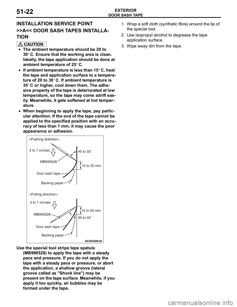
Use the special tool stripe tape spatula (MB990528) to apply the tape with a steady
pace and pressure. If you do not apply the
tape with a steady pace or pressure, or abort
the application, a shallow groove (lateral
groove called as "Shock line") may be
present on the tape surface. Meanwhile, if you
apply it too quickly, air bubbles may be
formed under the tape.
1. Wrap a soft cloth (synthetic fibre) around the tip of
the special tool.
2. Use isopropyl alcohol to degrease the tape application surface.
3. Wipe away dirt from the tape.
Page 360 of 800

WINDSHIELD WIPER AND WASHER
EXTERIOR51-28
WINDSHIELD WIPER AND WASHER
GENERAL INFORMATIONM1511000100514
WINDSHIELD WIPER AND WASHER
OPERATION
Windshield Low-speed (and High-speed)
Wiper Operation
•If the windshield low-speed wiper switch is turned
to the ON position with the ignition switch at the
"ACC" or "ON" position, the column switch sends
a low-speed wiper ON and high-speed wiper OFF
signals to the front-ECU. This turns the wiper sig
-
nal on and the wiper speed control relay off
(low-speed), causing the wipers to operate at
low-speed.
•If the windshield high-speed wiper switch is
turned to the ON position, the column switch
sends a low-speed wiper OFF and high-speed
wiper ON signals to the front-ECU. This turns
both the wiper signal and the wiper speed control
relay on (high-speed), causing the wipers to
operate at high-speed.
NOTE: The windshield wiper speed is switchable
with the built-in wiper speed control relay.
High-speed operations take place when the wiper
speed control relay is set to "ON" and low-speed
operations take place when the wiper speed control
relay is set to "OFF".
Windshield Intermittent Wiper Operation
The ETACS-ECU calculates the wiper operation
interval according to the voltage signal sent from the
column switch. Then the ETACS-ECU sends a signal
to the front-ECU. The front-ECU determines the
wiper operation interval and turns on the wiper relay
signal relay. This causes the wiper auto stop relay to
turn on. Then the wiper auto stop relay will turn off
after the wipers reach the park position. This causes
the wiper signal relay and then the wipers to turn off.
If the wiper signal relay remains off for the wiper
operation interval, the relay turns on again, causing
the wipers to operate in intermittent mode.
Windshield Mist Wiper Operation
•If the windshield mist wipe r switch is turned to the
ON position with the ignition switch at the "ACC"
or "ON" position, the mist wiper high-speed oper
-
ation signal is sent to the front-ECU. This signal
turns on the wiper speed control relay, causing
the wipers to work at high-speed while the mist
switch is on.
•While the windshield mist wiper switch remains
turned on when the intermittent mode is still work
-
ing, the wipers work as the mist wiper. However,
the wipers return to the intermittent mode again
when the switch is changed back to "INT" posi
-
tion.
•To prevent the windshield mist wiper from operat-
ing when the windshield wiper switch is turned
OFF, the windshield mist wiper does not work for
0.5 second after the windshi eld intermittent wiper
switch, the windshield low-speed wiper switch
and the windshield high-speed wiper switch are
turned OFF.
Windshield Washer Operation
•If the windshield washer switch is turned to ON
position with the ignition sw itch at "ACC" or "ON"
position, the windshield wa sher ON signal is sent
to the front-ECU. After 0.3 second, the windshield
wiper signal turns on. After the windshield washer
switch signal turns off, the windshield wiper signal
turns off in three seconds.
•If the windshield washer switch is turned on while
the windshield wiper is at intermittent mode,
when the windshield washer switch is turned OFF
within 0.2 second, the wiper works only once to
perform mist operation by the windshield washer
switch. When the ON condi tion of the windshield
washer switch continues more than 0.2 second,
the wiper performs the same movement as nor
-
mal condition from the time when 0.2 second has
elapsed and then returns to the intermittent
motion.
SERVICE SPECIFICATION
M1511000300325
ItemStandard value
Windshield wiper blade park position mm34 ± 5
Page 364 of 800
Wiper blade assembly removal steps
>>B<<1.Wiper blade assembly
>>A<<2.Wiper blade
Windshield wiper motor and link
assembly removal steps
3.Cover
4.Wiper arm
5.Hood weather strip
6.Front deck garnish (passenger's side)
7.Front deck garnish (driver's side)
<>8.Windshield wiper motor assembly
9.Link assembly
Washer hose removal steps
•Front splash shield (Refer to GROUP
42, Fender
P.42-6)
10.Rear washer hose
11 .Front washer hose
Windshield washer nozzle removal
steps
•Connection of front washer hose
11 .Washer nozzle
Washer tank and washer motor
removal steps
•Side undercover (RH)
•Front splash shield (Refer to GROUP
42, Fender
P.42-6)
•Connection of front washer hose and
rear washer hose
12.Washer tank assembly
13.Front washer motor
14.Rear washer motor
WINDSHIELD W I PER AND W A SHER
EXTERIOR51-32
NOTE: For re moval a nd in st allation of the wiper an d
washer switch, refer to GROUP 54A, Colu mn switch
P.5 4 A - 89.
REMOV A L SER V ICE POINT
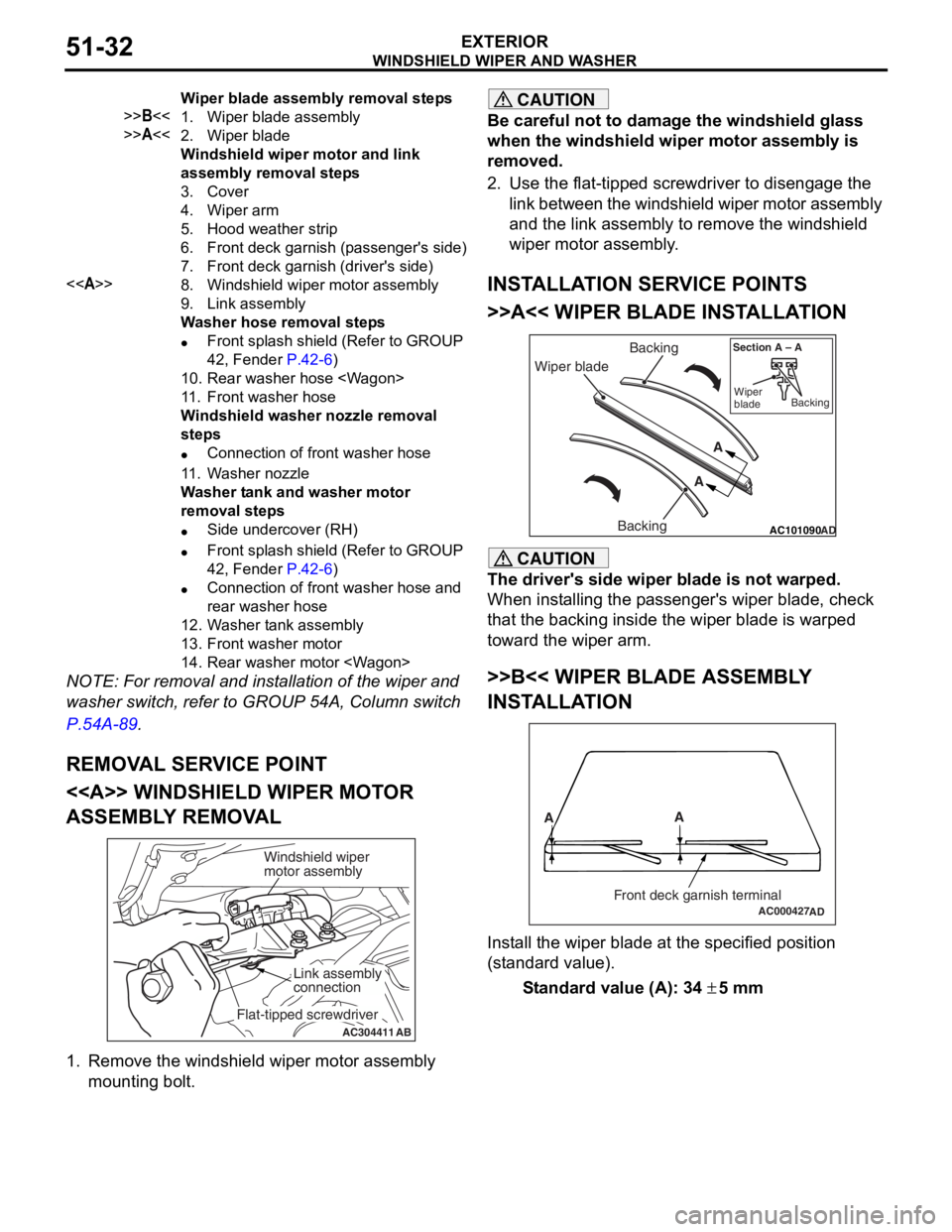
<> WI NDSHIELD W I PER MOT O R
ASSEMBL
Y REMOV A L
AC304411AB
Windshield wiper
motor assembly
Link assembly
connection
Flat-tipped screwdriver
1.
Remove the win d shield wiper motor asse mbly
mounting bo lt.
CAUTION
Be careful not to damage the windshield glass
when the windshield wiper motor assembly is
removed.
2. Use the flat-tipped screwdriver to disengage the link between the windshield wiper motor assembly
and the link assembly to remove the windshield
wiper motor assembly.
INSTALLATION SERVICE POINTS
>>A<< WIPER BLADE INSTALLATION
AC101090 AD
Wiper blade Backing
Backing A
A
Section A – A
Wiper
blade Backing
CAUTION
The driver's side wiper blade is not warped.
When installing the passenger's wiper blade, check
that the backing inside the wiper blade is warped
toward the wiper arm.
>>B<< WIPER BLADE ASSEMBLY
INSTALLATION
AC000427
A
A
Front deck garnish terminalAD
Install the wiper blade at the specified position
(standard value).
Standard value (A): 34 ± 5 mm
Page 368 of 800
REAR WIPER AND WASHER
EXTERIOR51-36
TROUBLESHOOTING
M1511000700334
The rear wiper and washer are controlled by the
Smart Wiring System (SWS). For troubleshooting,
refer to GROUP 54B, Troubleshooting
P.54B-15 or
GROUP 54C, Troubleshooting P.54C-4.
ON-VEHICLE SERVICE
M1511000800472
CHECK OF REAR WIPER OPERATION
WHEN SELECTOR LEVER IS AT THE "R"
POSITION
1. When the selector lever is moved to the "R" position with the rear wiper switch at the "INT"
position, the wiper should operate twice or three
times at low speed after approximately one
second.
2. If not, carry out the troubleshooting (Refer to GROUP 54B, Troubleshooting
P.54B-15 or
GROUP 54C, Troubleshooting P.54C-4).
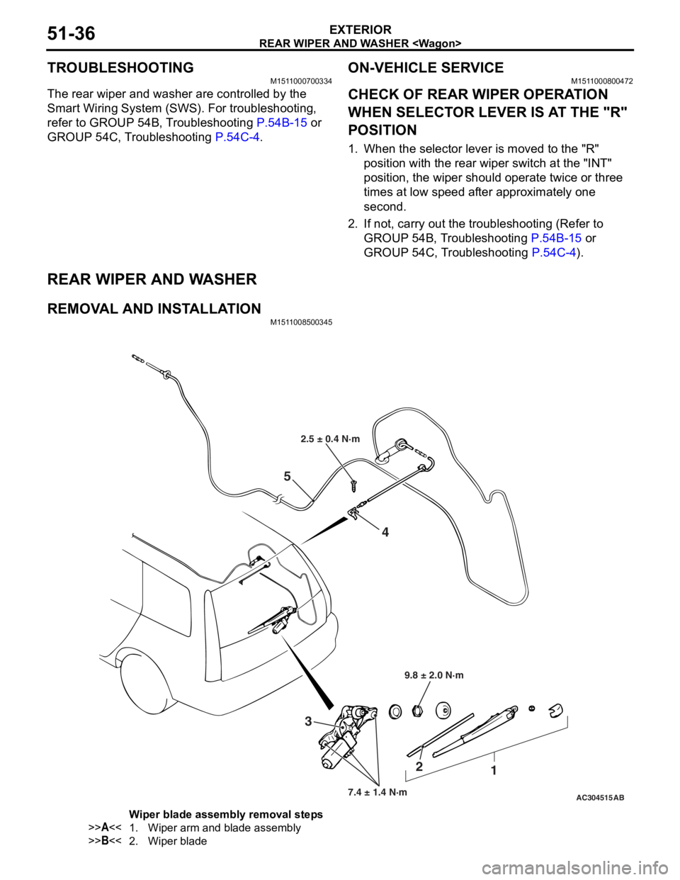
REAR WIPER AND WASHER
REMOVAL AND INSTALLATIONM1511008500345
AC304515
2.5 ± 0.4 N·m
9.8 ± 2.0 N·m
7.4 ± 1.4 N·m
3 2
1
4
5
AB
Wiper blade assembly removal steps
>>A<<1.Wiper arm and blade assembly
>>B<<2.Wiper blade
Page 375 of 800
DOOR MIRROR
EXTERIOR51-43
DOOR MIRROR
GENERAL INFORMATIONM1511000100536
DOOR MIRROR OPERATION
Remote Controlled Mirror Operation
•The mirror on the door mirror moves up/down
and left/right by operating the remote controlled
door mirror switch when the ignition switch is in
the "ON" or "ACC" position.
Heated Door Mirror operation
•The defogger relay switch is activated (ON) by
turning on the A/C-ECU built-in defogger switch
when the ignition switch is in the "ON" position.
When the defogger relay is turned ON, power is
supplied to the defogger and door mirror, and the
heater of the door mirror (heated door mirror)
starts operations. The defogger comes with a
timer function and will automatically turn OFF the
switch approximately 11 minutes after the defog
-
ger switch is turned ON. The heated door mirror
operations are also terminated along with the
defogger, at this time.
SERVICE SPECIFICATION
M1511000300347
ItemStandard value
Heated door mirror operation current Ω5.9 − 7.8
SPECIAL TOOL
M1511000601103
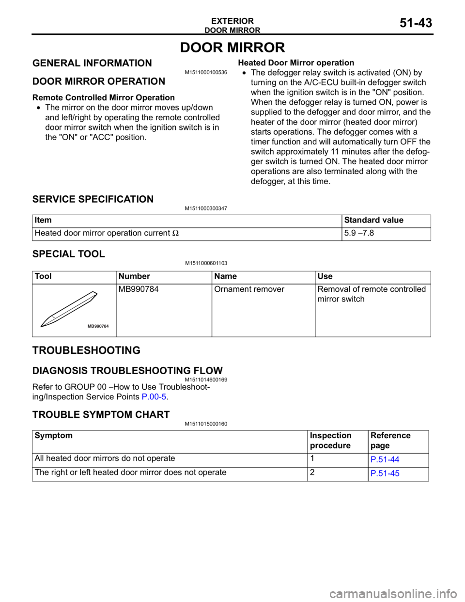
ToolNumberNameUse
MB990784
MB990 784Ornament removerRemoval of remote controlled
mirror switch
TROUBLESHOOTING
DIAGNOSIS TROUBLESHOOTING FLOW
M151 1 0146 0016 9
Refe r to GROUP 00 − How to Use T r o ubleshoot-
ing/Inspectio n Service Point s P.00-5.
TR OUBLE SYM PT OM CHARTM151 1 0150 0016 0
SymptomInspection
procedureReference
page
All heated door mirrors do not operate1P.51-44
The right or left heated door mirror does not operate2P.51-45
Page 383 of 800
DOOR MIRROR
EXTERIOR51-51
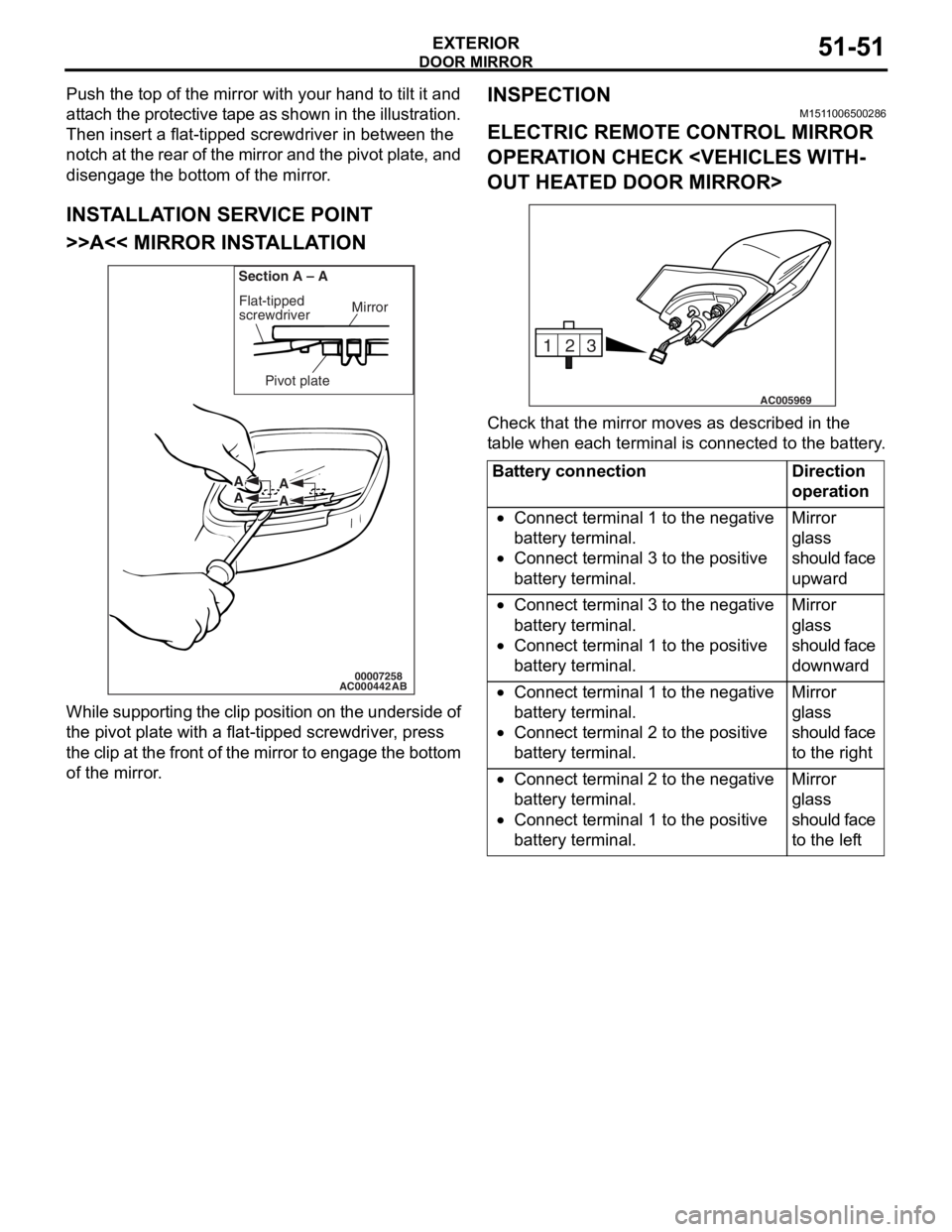
Push the top of the mirror with your hand to tilt it and
attach the protective tape as shown in the illustration.
Then insert a flat-tipped screwdriver in between the
notch at the rear of the mirror and the pivot plate, and
disengage the bottom of the mirror.
INSTALLATION SERVICE POINT
>>A<< MIRROR INSTALLATION
AC00044200007258
Mirror
Flat-tipped
screwdriver
Section A – A
Pivot plate
A
A A
A
AB
W h il e su pp ort i ng t he clip po siti on on th e u nde rsi de of
the pivot p
l ate with a flat -tipped screwdr i ver , press
t
he clip at th e front of the mirror t o engage t he botto m
of the mirro
r .
INSPECTION
M151 1 0065 0028 6
ELECTRIC REMOTE CONTROL MIRROR
OPERA
T ION CHECK < V EHICLES WITH
-
OUT HEAT ED DOOR MIRROR>
3
2
1
AC005969
Ch eck that th e mirror moves as describe d in the
t
a b l e when each terminal is conn ecte d to the batte ry .
Battery connectionDirection
operation
•Connect terminal 1 to the negative
battery terminal.
•Connect terminal 3 to the positive
battery terminal.
Mirror
glass
should face
upward
•Connect terminal 3 to the negative
battery terminal.
•Connect terminal 1 to the positive
battery terminal.
Mirror
glass
should face
downward
•Connect terminal 1 to the negative
battery terminal.
•Connect terminal 2 to the positive
battery terminal.
Mirror
glass
should face
to the right
•Connect terminal 2 to the negative
battery terminal.
•Connect terminal 1 to the positive
battery terminal.
Mirror
glass
should face
to the left