control MITSUBISHI LANCER 2006 Workshop Manual
[x] Cancel search | Manufacturer: MITSUBISHI, Model Year: 2006, Model line: LANCER, Model: MITSUBISHI LANCER 2006Pages: 800, PDF Size: 45.03 MB
Page 442 of 800
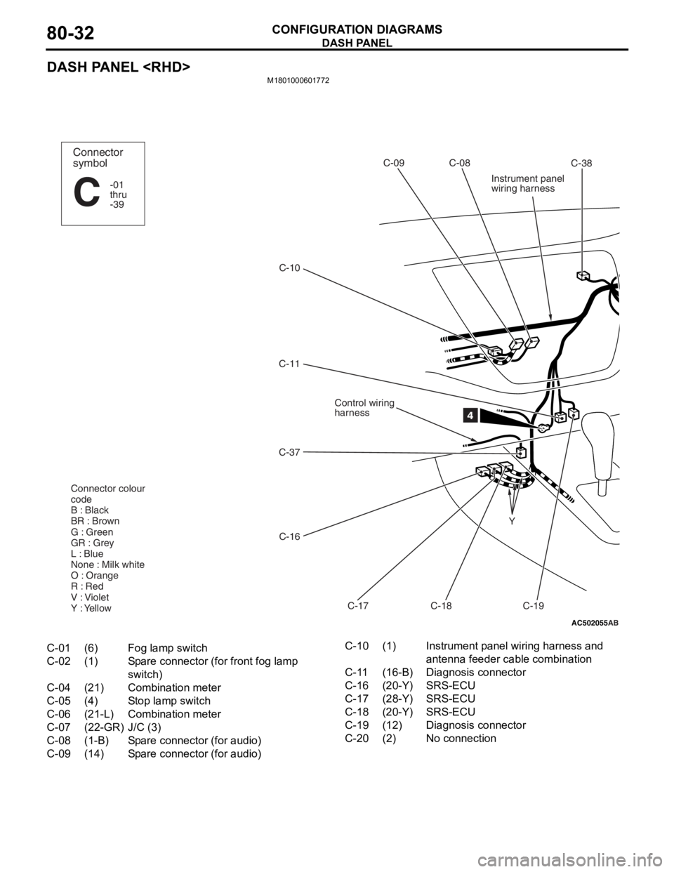
DASH PANEL
CONFIGURATION DIAGRAMS80-32
DASH PANEL
M1801000601772
AC502055
C-10C-09 C-08
Control wiring
harness
C-37
C-16 C-17 C-18
C-11
C-19
Y
4
Connector
symbol
-01
thru
-39
C
Connector colour
code
B : Black
BR : Brown
G : Green
GR : Grey
L : Blue
None : Milk white
O : Orange
R : Red
V : Violet
Y : Yellow
Instrument panel
wiring harness
C-38
AB
C-01(6)Fog lamp switch
C-02(1)Spare connector (for front fog lamp
switch)
C-04(21)Combination meter
C-05(4)Stop lamp switch
C-06(21-L)Combination meter
C-07(22-GR)J/C (3)
C-08(1-B)Spare connector (for audio)
C-09(14)Spare connector (for audio)
C-10(1)Instrument panel wiring harness and
antenna feeder cable combination
C-11(16-B)Diagnosis connector
C-16(20-Y)SRS-ECU
C-17(28-Y)SRS-ECU
C-18(20-Y)SRS-ECU
C-19(12)Diagnosis connector
C-20(2)No connection
Page 443 of 800
AC502056
C-39
AB
C-04 C-07 C-06 C-05 C-02 C-01J/B C-34
C-33
C-31
C-30
C-28
C-26
C-23 C-24
C-20 C-32
C-35
2
C-36
6
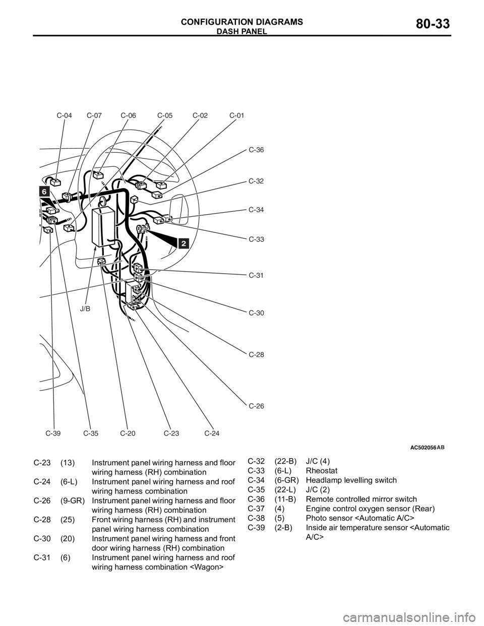
C-23(13)Instrument panel wiring harness and floor
wiring harness ( RH) combination
C-24(6-L)Instrument panel wiring harness and roof
wiring harness combination
C-26(9-GR)Instrument panel wiring harness and floor
wiring harness (RH) combination
C-28(25)Front wiring harness (RH) and instrument
panel wiring harn ess combination
C-30(20)Instrument panel wiring harness and front
door wiring harness (RH) combination
C-31(6)Instrument panel wiring harness and roof
wiring harness combination
C-32(22-B)J/C (4)
C-33(6-L)Rheostat
C-34(6-GR)Headlamp levelling switch
C-35(22-L)J/C (2)
C-36(11-B)Remote controlled mirror switch
C-37(4)Engine control oxygen sensor (Rear)
C-38(5)Photo sensor
C-39(2-B)Inside air temperature sensor
DASH P ANEL
CONF IGURA TION D I A G RA MS80-33
Page 444 of 800
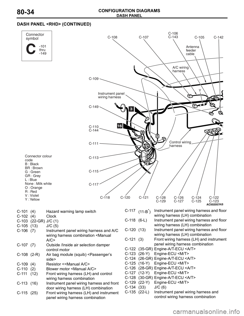
DASH PANEL
CONFIGURATION DIAGRAMS80-34
DASH PANEL
AC502057
Y
16
C-105
C-106
C-143
C-107
C-108
A/C wiring
harness
C-109
C-149
C-110
C-144
C-111
C-113
C-115
C-117
Instrument panel
wiring harness
Control wiring
harness
C-118 C-120
C-121C-128
C-129 C-126
C-127C-124
C-125
C-122
C-123
Connector colour
code
B : Black
BR : Brown
G : Green
GR : Grey
L : Blue
None : Milk white
O : Orange
R : Red
V : Violet
Y : Yellow
3
Connector
symbol
-101
thru
-149
C
Antenna
feeder
cable
AB
C-142
C-101(4)Hazard warning lamp switch
C-102(4)Clock
C-103(22-GR)J/C (1)
C-105(13)J/C (5)
C-106(7)Instrument panel wiring harness and A/C
wiring harness combination
C-107(7)Outside /Inside air selection damper
control motor
C-108(2-R)Air bag module (squib)
C-109(4)Resistor <
C-110(2)Blower motor
C-111(12)Front wiring harness (LH) and control
wiring harness combination
C-113(16)Instrument panel wiring harness and front
door wiring harness (LH) combination
C-115(25)Front wiring harness (LH) and instrument
panel wiring harn
ess combination
C-117(11-B*)Instrument panel wiring harness and floor
wiring harness (LH) combination
C-118(6-L)Instrument panel wiring harness and floor
wiring harness (LH) combination
C-120(13)Instrument panel wiring harness and floor
wiring harness (LH) combination
C-121(3)Front wiring harness (LH) and instrument
panel wiring harness combination
C-122(35-GR)Engine-A/T-ECU
C-123(26-Y)Engine-ECU
C-124(26-GR)Engine-A/T-ECU
C-125(16-Y)Engine-ECU
C-126(28-GR)Engine-A/T-ECU
C-127(12-Y)Engine-ECU
C-128(30-GR)Engine-A/T-ECU
C-129(22-Y)Engine-ECU
C-134(33)J/C (6)
C-135(22-L)Instrument panel wiring harness and
control wiring harness combination
Page 445 of 800
AC502058AB
5
14
15
C-103C-102
C-101
C-148
C-147C-138
C-146
C-137 C-140
C-139
C-136
C-135
C-134
C-145
C-141
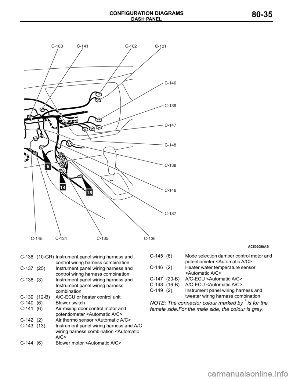
C-136(10-GR)Instrument panel wiring harness and
control wiring harness combination
C-137(25)Instrument panel wiring harness and
control wiring harness combination
C-138(3)Instrument panel wiring harness and
Instrument panel wiring harness
combination
C-139(12-B)A/C-ECU or heater control unit
C-140(6)Blower switch
C-141(6)Air mixing door control motor and
potentiometer
C-142(2)Air thermo sensor
C-143(13)Instrument panel wiring harness and A/C
wiring harness combination
C-144(6)Blower motor
C-145(6)Mode selection damper control motor and
potentiometer
C-146(2)Heater water temperature sensor
C-147(20-B)A/C-ECU
C-148(16-B)A/C-ECU
C-149(2)Instrument panel wiring harness and
tweeter wiring harn ess combination
DASH P ANEL
CONF IGURA TION D I A G RA MS80-35
NOTE: The conn ecto r colour marked by * is fo r the
female side.F
o
r the male
sid
e
, the
colour is grey .
Page 456 of 800
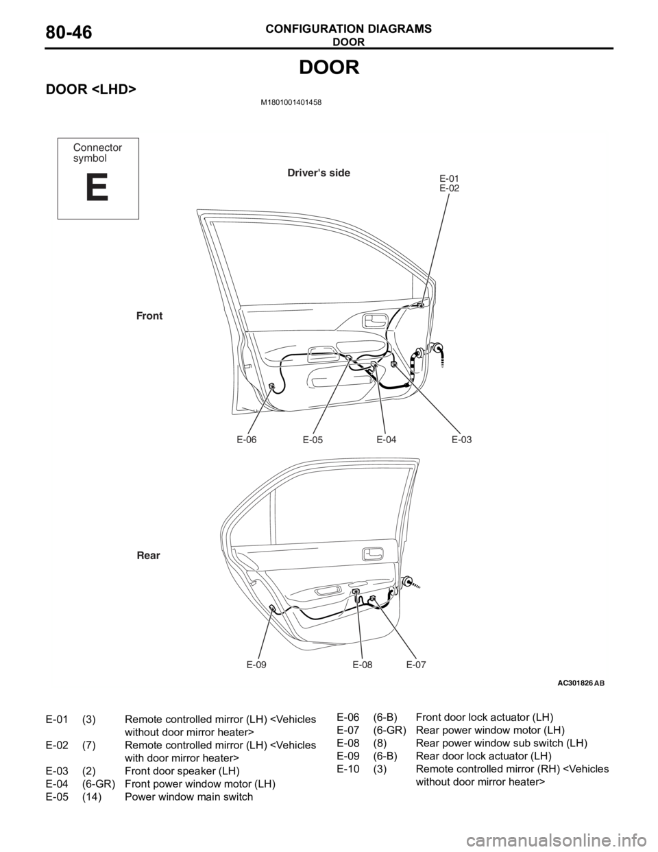
DOOR
CONFIGURATION DIAGRAMS80-46
DOOR
DOOR
AC301826
Connector
symbol
E
Driver's sideE-01
E-02E-03
E-04
E-05
E-06
E-07
E-08
E-09
Front
Rear
AB
E-01(3)Remote controlled mirror (LH)
E-02(7)Remote controlled mirror (LH)
E-03(2)Front door speaker (LH)
E-04(6-GR)Front power window motor (LH)
E-05(14)Power window main switch
E-06(6-B)Front door lock actuator (LH)
E-07(6-GR)Rear power window motor (LH)
E-08(8)Rear power window sub switch (LH)
E-09(6-B)Rear door lock actuator (LH)
E-10(3)Remote controlled mirr or (RH)
Page 457 of 800
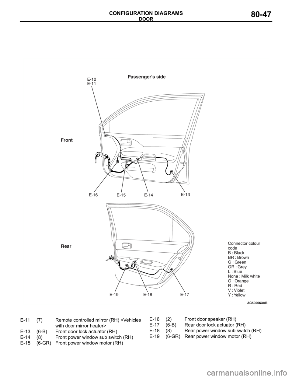
AC502063
Passenger's sideE-10
E-11E-14
E-15
E-16
E-17
E-18
E-19
Front
Rear
AB
E-13 Connector colour
code
B : Black
BR : Brown
G : Green
GR : Grey
L : Blue
None : Milk white
O : Orange
R : Red
V : Violet
Y : Yellow
E-11(7)Remote controlled mirror (RH)
E-13(6-B)Front door lock actuator (RH)
E-14(8)Front power window sub switch (RH)
E-15(6-GR)Front power window motor (RH)
E-16(2)Front door speaker (RH)
E-17(6-B)Rear door lock actuator (RH)
E-18(8)Rear power window sub switch (RH)
E-19(6-GR)Rear power window motor (RH)
DOOR
CONF IGURA TION D I A G RA MS80-47
Page 458 of 800
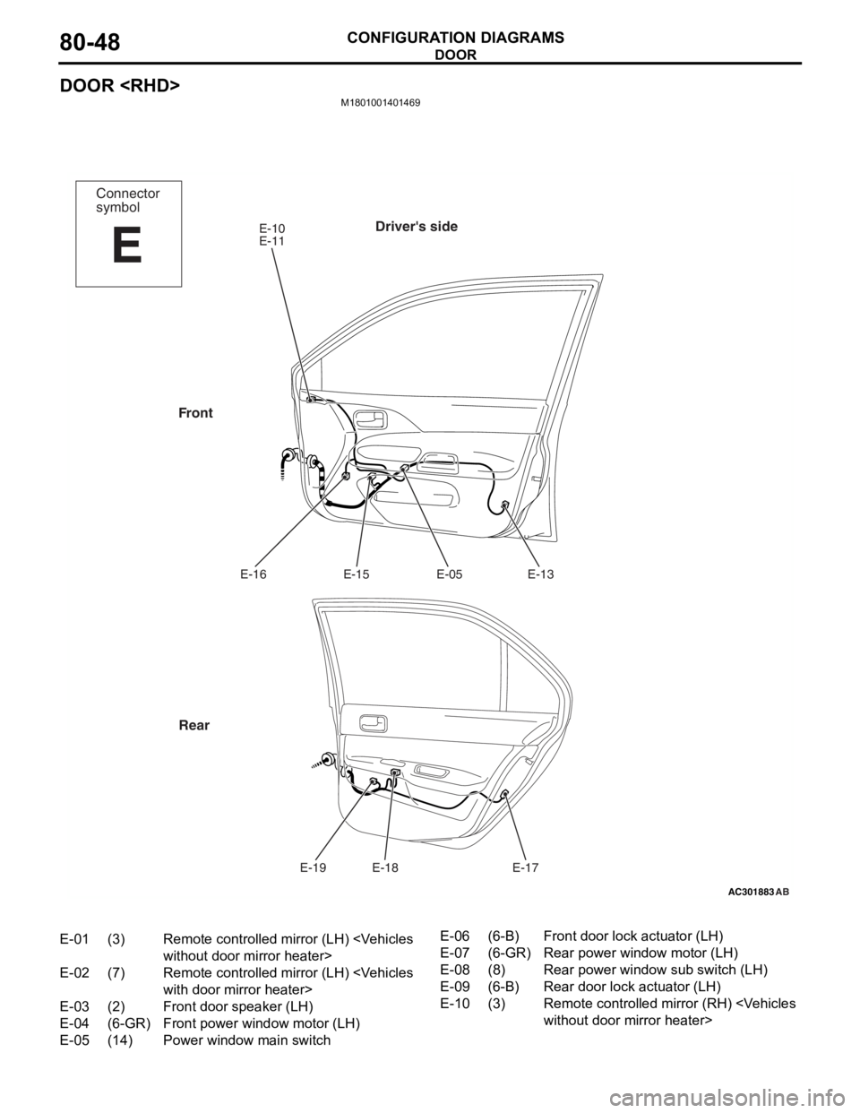
DOOR
CONFIGURATION DIAGRAMS80-48
DOOR
M1801001401469
AC301883
Connector
symbol
E
Driver's sideE-10
E-11E-13
E-05
E-15
E-16
E-17
E-18
E-19
Front
Rear
AB
E-01(3)Remote controlled mirror (LH)
E-02(7)Remote controlled mirror (LH)
E-03(2)Front door speaker (LH)
E-04(6-GR)Front power window motor (LH)
E-05(14)Power window main switch
E-06(6-B)Front door lock actuator (LH)
E-07(6-GR)Rear power window motor (LH)
E-08(8)Rear power window sub switch (LH)
E-09(6-B)Rear door lock actuator (LH)
E-10(3)Remote controlled mirr or (RH)
Page 459 of 800
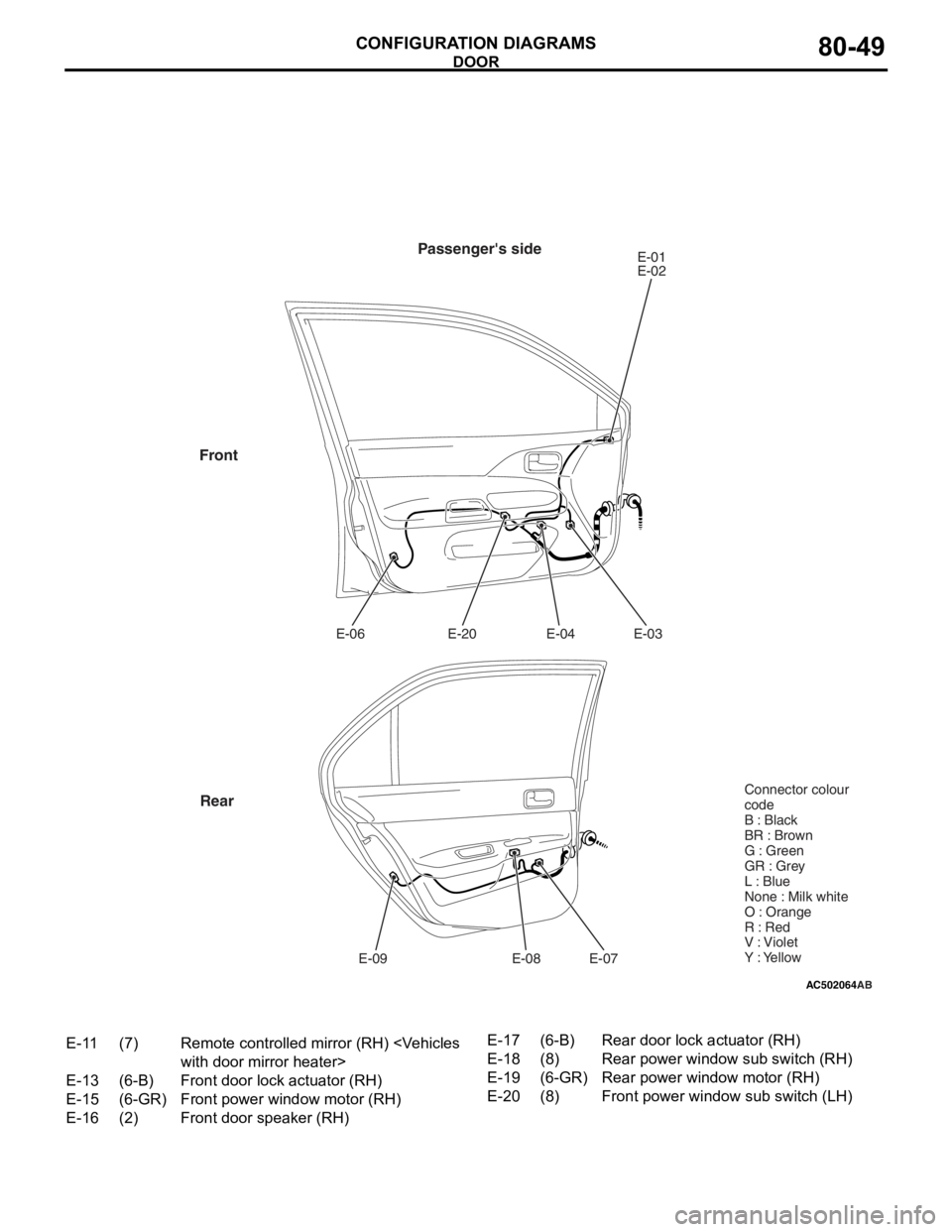
AC502064
Passenger's sideE-01
E-02
E-03
E-04
E-20
E-06
E-07
E-08
E-09
Front
Rear
AB
Connector colour
code
B : Black
BR : Brown
G : Green
GR : Grey
L : Blue
None : Milk white
O : Orange
R : Red
V : Violet
Y : Yellow
E-11(7)Remote controlled mirror (RH)
E-13(6-B)Front door lock actuator (RH)
E-15(6-GR)Front power window motor (RH)
E-16(2)Front door speaker (RH)
E-17(6-B)Rear door lock actuator (RH)
E-18(8)Rear power window sub switch (RH)
E-19(6-GR)Rear power window motor (RH)
E-20(8)Front power window sub switch (LH)
DOOR
CON F IGURA TION D I A G RA MS80-49
Page 465 of 800
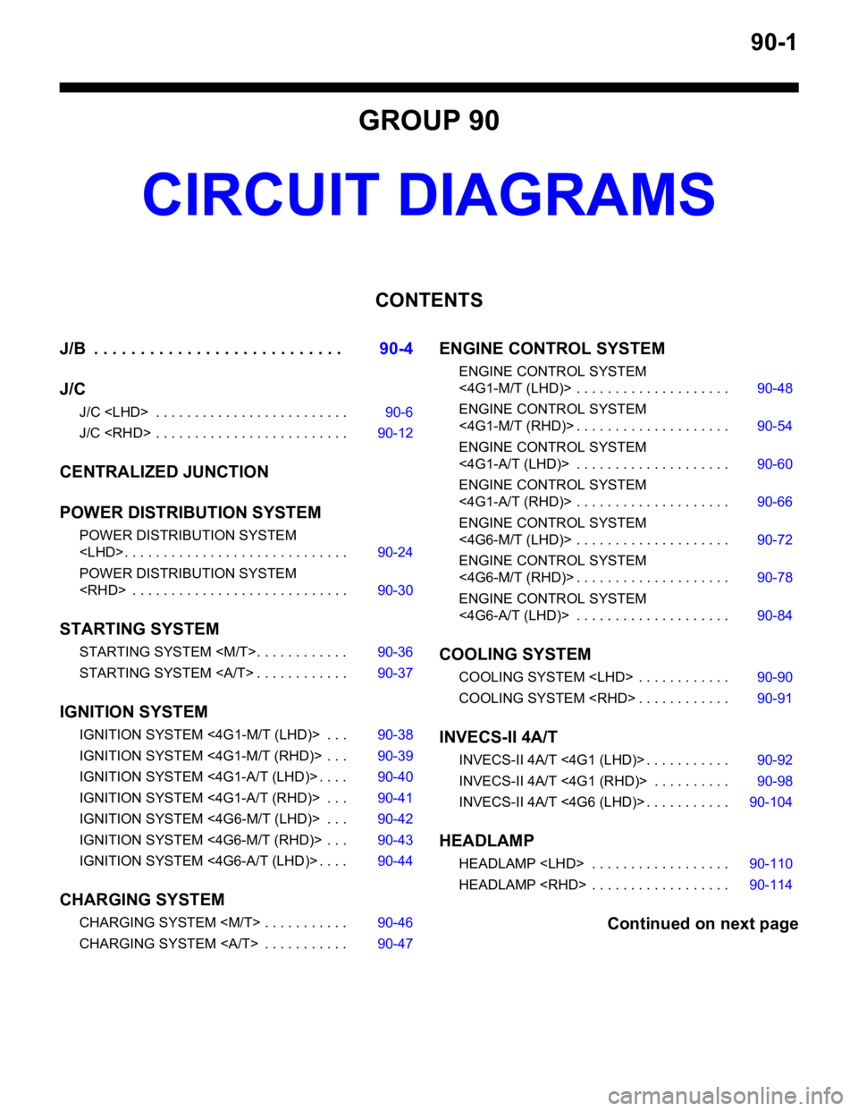
90-1
GROUP 90
CIRCUIT DIAGRAMS
CONTENTS
J/B . . . . . . . . . . . . . . . . . . . . . . . . . . .90-4
J/C
J/C
J/C
CENTRALIZED JUNCTION
POWER DISTRIBUTION SYSTEM
POWER DISTRIBUTION SYSTEM
POWER DISTRIBUTION SYSTEM
STARTING SYSTEM
STARTING SYSTEM
STARTING SYSTEM . . . . . . . . . . . . 90-37
IGNITION SYSTEM
IGNITION SYSTEM <4 G1-M/T (LHD)> . . . 90-38
IGNITION SYSTEM <4G1-M/T (RHD)> . . . 90-39
IGNITION SYSTEM <4G1-A/T (LHD)> . . . . 90-40
IGNITION SYSTEM <4G1-A/T (RHD)> . . . 90-41
IGNITION SYSTEM <4G6-M/T (LHD)> . . . 90-42
IGNITION SYSTEM <4G6-M/T (RHD)> . . . 90-43
IGNITION SYSTEM <4G6-A/T (LHD)> . . . . 90-44
CHARGING SYSTEM
CHARGING SYSTEM
CHARGING SYSTEM . . . . . . . . . . . 90-47
ENGINE CONTROL SYSTEM
ENGINE CONTROL SYSTEM
<4G1-M/T (LHD)> . . . . . . . . . . . . . . . . . . . . 90-48
ENGINE CONTROL SYSTEM
<4G1-M/T (RHD)> . . . . . . . . . . . . . . . . . . . . 90-54
ENGINE CONTROL SYSTEM
<4G1-A/T (LHD)> . . . . . . . . . . . . . . . . . . . . 90-60
ENGINE CONTROL SYSTEM
<4G1-A/T (RHD)> . . . . . . . . . . . . . . . . . . . . 90-66
ENGINE CONTROL SYSTEM
<4G6-M/T (LHD)> . . . . . . . . . . . . . . . . . . . . 90-72
ENGINE CONTROL SYSTEM
<4G6-M/T (RHD)> . . . . . . . . . . . . . . . . . . . . 90-78
ENGINE CONTROL SYSTEM
<4G6-A/T (LHD)> . . . . . . . . . . . . . . . . . . . . 90-84
COOLING SYSTEM
COOLING SYSTEM
COOLING SYSTEM
INVECS-II 4A/T
INVECS-II 4A/T <4G1 (LHD)> . . . . . . . . . . . 90-92
INVECS-II 4A/T <4G1 (RHD)> . . . . . . . . . . 90-98
INVECS-II 4A/T <4G6 (LHD)> . . . . . . . . . . . 90-104
HEADLAMP
HEADLAMP
HEADLAMP
Continued on next page
Page 467 of 800
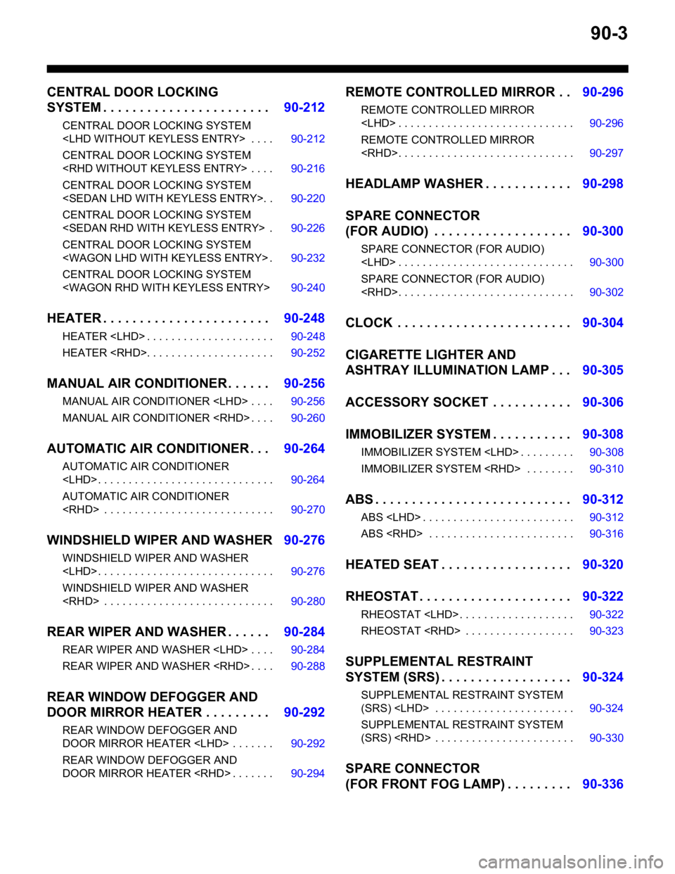
90-3
CENTRAL DOOR LOCKING
SYSTEM . . . . . . . . . . . . . . . . . . . . . . .90-212
CENTRAL DOOR LOCKING SYSTEM
CENTRAL DOOR LOCKING SYSTEM
CENTRAL DOOR LOCKING SYSTEM
CENTRAL DOOR LOCKING SYSTEM
CENTRAL DOOR LOCKING SYSTEM
CENTRAL DOOR LOCKING SYSTEM
HEATER . . . . . . . . . . . . . . . . . . . . . . .90-248
HEATER
HEATER
MANUAL AIR CONDITIONER . . . . . .90-256
MANUAL AIR CONDITIONER
MANUAL AIR CONDITIONER
AUTOMATIC AIR CONDITIONER . . .90-264
AUTOMATIC AIR CONDITIONER
AUTOMATIC AIR CONDITIONER
WINDSHIELD WIPER AND WASHER90-276
WINDSHIELD WIPER AND WASHER
WINDSHIELD WIPER AND WASHER
REAR WIPER AND WASHER . . . . . .90-284
REAR WIPER AND WASHER
REAR WIPER AND WASHER
REAR WINDOW DEFOGGER AND
DOOR MIRROR HEATER . . . . . . . . .90-292
REAR WINDOW DEFOGGER AND
DOOR MIRROR HEATER
REAR WINDOW DEFOGGER AND
DOOR MIRROR HEATER
REMOTE CONTROLLED MIRROR . .90-296
REMOTE CONTROLLED MIRROR
REMOTE CONTROLLED MIRROR
HEADLAMP WASHER . . . . . . . . . . . .90-298
SPARE CONNECTOR
(FOR AUDIO) . . . . . . . . . . . . . . . . . . .90-300
SPARE CONNECTOR (FOR AUDIO)
SPARE CONNECTOR (FOR AUDIO)
CLOCK . . . . . . . . . . . . . . . . . . . . . . . .90-304
CIGARETTE LIGHTER AND
ASHTRAY ILLUMINATION LAMP . . .90-305
ACCESSORY SOCKET . . . . . . . . . . .90-306
IMMOBILIZER SYSTEM . . . . . . . . . . .90-308
IMMOBILIZER SYSTEM
IMMOBILIZER SYSTEM
ABS . . . . . . . . . . . . . . . . . . . . . . . . . . .90-312
ABS
ABS
HEATED SEAT . . . . . . . . . . . . . . . . . .90-320
RHEOSTAT . . . . . . . . . . . . . . . . . . . . .90-322
RHEOSTAT
RHEOSTAT
SUPPLEMENTAL RESTRAINT
SYSTEM (SRS) . . . . . . . . . . . . . . . . . .90-324
SUPPLEMENTAL RESTRAINT SYSTEM
(SRS)
SUPPLEMENTAL RESTRAINT SYSTEM
(SRS)
SPARE CONNECTOR
(FOR FRONT FOG LAMP) . . . . . . . . .90-336