control MITSUBISHI LANCER 2006 Manual Online
[x] Cancel search | Manufacturer: MITSUBISHI, Model Year: 2006, Model line: LANCER, Model: MITSUBISHI LANCER 2006Pages: 800, PDF Size: 45.03 MB
Page 382 of 800
DOOR MIRROR
EXTERIOR51-50
DOOR MIRROR
REMOVAL AND INSTALLATION
M1511006400308
AC304733
Note
: Claw positions
AB
AA
Section A – A
Claw1
2
12 3 4
5
6
7
8
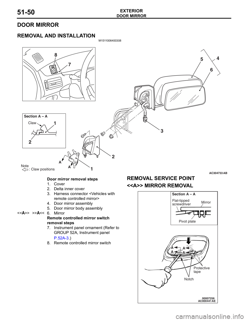
Door mirror removal steps
1.Cover
2.Delta inner cover
3.Harness connector
4.Door mirror assembly
5.Door mirror body assembly
<>>>A<<6.Mirror
Remote controlled mirror switch
removal steps
7.Instrument panel ornament (Refer to
GROUP 52A, Instrument panel
P.52A-3.)
8.Remote controlled mirror switch
REMOV
A L SER VICE POINT
<> MIRROR REMOV A L
AC00044100007256
Mirror
Flat-tipped
screwdriver
Section A – A
Pivot plate
Notch
Protective
tape
A
A A
A
AE
Page 383 of 800
DOOR MIRROR
EXTERIOR51-51
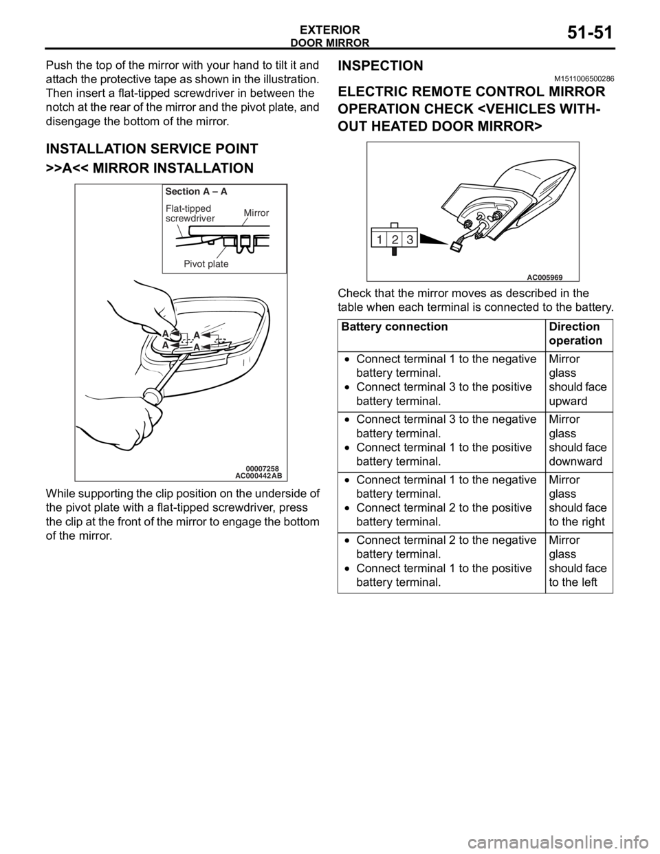
Push the top of the mirror with your hand to tilt it and
attach the protective tape as shown in the illustration.
Then insert a flat-tipped screwdriver in between the
notch at the rear of the mirror and the pivot plate, and
disengage the bottom of the mirror.
INSTALLATION SERVICE POINT
>>A<< MIRROR INSTALLATION
AC00044200007258
Mirror
Flat-tipped
screwdriver
Section A – A
Pivot plate
A
A A
A
AB
W h il e su pp ort i ng t he clip po siti on on th e u nde rsi de of
the pivot p
l ate with a flat -tipped screwdr i ver , press
t
he clip at th e front of the mirror t o engage t he botto m
of the mirro
r .
INSPECTION
M151 1 0065 0028 6
ELECTRIC REMOTE CONTROL MIRROR
OPERA
T ION CHECK < V EHICLES WITH
-
OUT HEAT ED DOOR MIRROR>
3
2
1
AC005969
Ch eck that th e mirror moves as describe d in the
t
a b l e when each terminal is conn ecte d to the batte ry .
Battery connectionDirection
operation
•Connect terminal 1 to the negative
battery terminal.
•Connect terminal 3 to the positive
battery terminal.
Mirror
glass
should face
upward
•Connect terminal 3 to the negative
battery terminal.
•Connect terminal 1 to the positive
battery terminal.
Mirror
glass
should face
downward
•Connect terminal 1 to the negative
battery terminal.
•Connect terminal 2 to the positive
battery terminal.
Mirror
glass
should face
to the right
•Connect terminal 2 to the negative
battery terminal.
•Connect terminal 1 to the positive
battery terminal.
Mirror
glass
should face
to the left
Page 384 of 800
DOOR MIRROR
EXTERIOR51-52
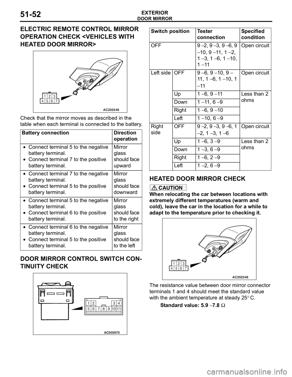
ELECTRIC REMOTE CONTROL MIRROR
OPERATION CHECK
AC202548
1
4567 23
Che
c k that th e mirror moves as describe d in the
t
a b l e when each terminal is conn ecte d to the batter y .
Battery connectionDirection
operation
•Connect terminal 5 to the negative
battery terminal.
•Connect terminal 7 to the positive
battery terminal.
Mirror
glass
should face
upward
•Connect terminal 7 to the negative
battery terminal.
•Connect terminal 5 to the positive
battery terminal.
Mirror
glass
should face
downward
•Connect terminal 5 to the negative
battery terminal.
•Connect terminal 6 to the positive
battery terminal.
Mirror
glass
should face
to the right
•Connect terminal 6 to the negative
battery terminal.
•Connect terminal 5 to the positive
battery terminal.
Mirror
glass
should face
to the left
DOOR MIRROR CONTROL SWITCH CON-
TINUITY CHECK
AC005970
2
14
3
510 9
8
7
6
11
Switch positionTester
connectionSpecified
condition
OFF9 − 2, 9 − 3, 9 − 6, 9
− 10, 9 − 11, 1 − 2,
1
− 3, 1 − 6, 1 − 10,
1
− 11
Open circuit
Left sideOFF9 − 6, 9 − 10, 9 −
11 , 1
− 6, 1 − 10, 1
− 11
Open circuit
Up1 − 6, 9 − 11Less than 2
ohms
Down1 − 11, 6 − 9
Right1 − 6, 9 − 10
Left1 − 10, 6 − 9
Right
sideOFF9 − 2, 9 − 3, 9 − 6, 1
− 2, 1 − 3, 1 − 6
Open circuit
Up1 − 6, 3 − 9Less than 2
ohms
Down1 − 3, 6 − 9
Right1 − 6, 2 − 9
Left1 − 2, 6 − 9
HEA T ED DOOR MIRROR CHECK
CAUTION
When relocating the car between locations with
extremely different temperatures (warm and
cold), leave the car in the location for a while to
adapt to the temperature prior to checking it.
AC202548
1
4567 23
The resistance value between door mirror connector
terminals 1 and 4 should meet the standard value
with the ambient temperature at steady 25
°C.
Standard value: 5.9 − 7.8 Ω
Page 392 of 800
ECU
COMPONENT LOCATIONS70-2
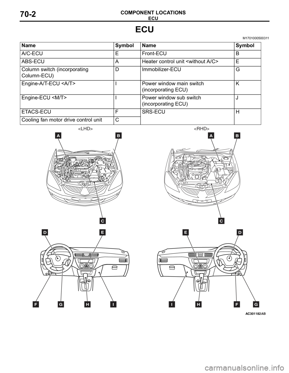
ECU
M1701000500311
NameSymbolNameSymbol
A/C-ECUEFront-ECUB
ABS-ECUAHeater control unit
Column switch (incorporating
Column-ECU)DImmobilizer-ECUG
Engine-A/T-ECU IPower window main switch
(incorporating ECU)K
Engine-ECU
(incorporating ECU)J
ETACS-ECUFSRS-ECUH
Cooling fan motor drive control unitC
AC301182
DE
AB
C
FGHI
AB
DE
AB
C
FGHI
Page 393 of 800
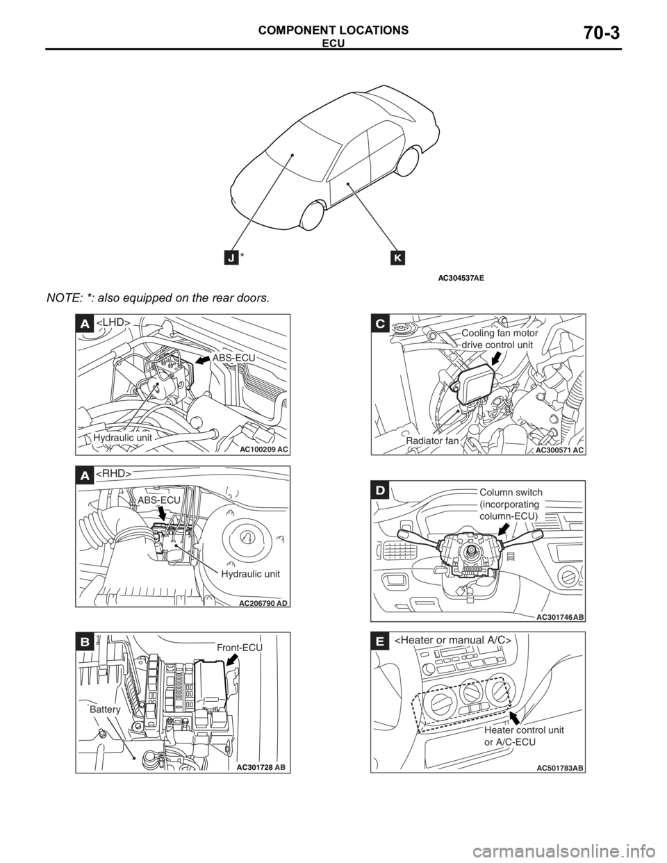
AC304537
JK*
AE
ECU
COMPONENT LOCA TIONS70-3
NOTE: *: also eq uipp ed on the rear doors.
AC100209AC
A
ABS-ECU
Hydraulic unit
AC206790
A
AD
ABS-ECU
Hydraulic unit
AC301728AB
BFront-ECU
Battery
AC300571
C
ACRadiator fan
Cooling fan motor
drive control unit
AC301746
DColumn switch
(incorporating
column-ECU)
AB
AC501783AB
E
Heater control unit
or A/C-ECU
Page 395 of 800
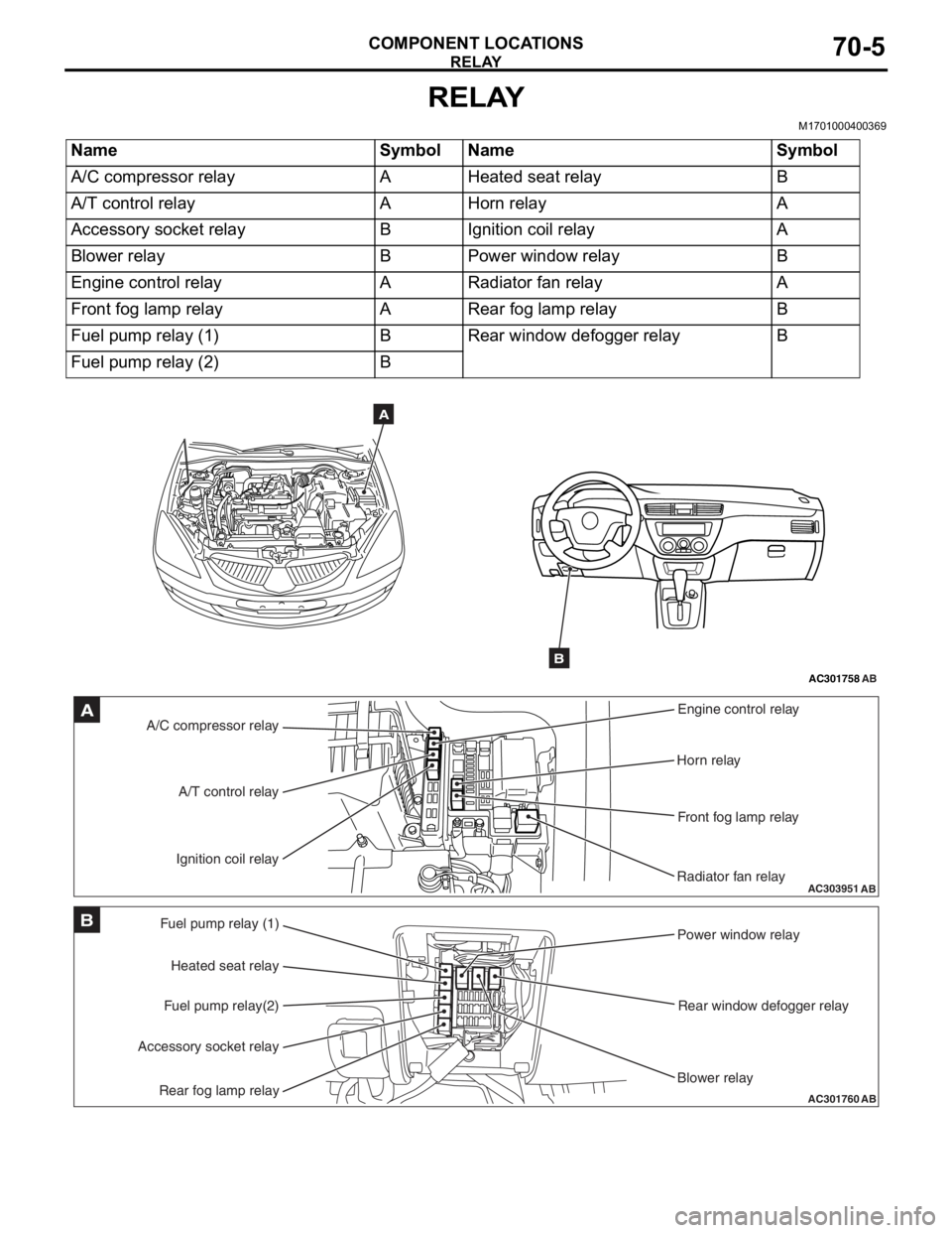
RELAY
COMPONENT LOCATIONS70-5
RELAY
M1701000400369
NameSymbolNameSymbol
A/C compressor relayAHeated seat relayB
A/T control relayAHorn relayA
Accessory socket relayBIgnition coil relayA
Blower relayBPower window relayB
Engine control relayARadiator fan relayA
Front fog lamp relayARear fog lamp relayB
Fuel pump relay (1)BRear window defogger relayB
Fuel pump relay (2)B
AC301758AB
A
B
AC303951AB
A/C compressor relayEngine control relay
Horn relay
Front fog lamp relay
Radiator fan relay
A/T control relay
Ignition coil relayA
AC301760
Fuel pump relay (1) Power window relay
Rear window defogger relay
Blower relay
Heated seat relay
Fuel pump relay(2)
Accessory socket relay
Rear fog lamp relayAB
B
Page 396 of 800
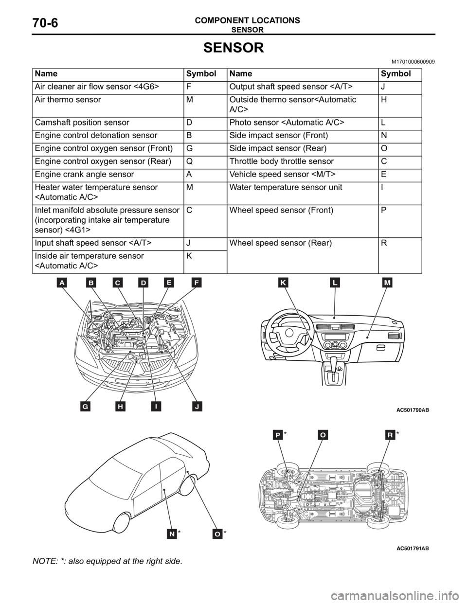
SENSOR
COMPONENT LOCATIONS70-6
SENSOR
M1701000600909
NameSymbolNameSymbol
Air cleaner air flow sensor <4G6>FOutput shaft speed sensor J
Air thermo sensorMOutside thermo sensor
Camshaft position sensorDPhoto sensor
Engine control detonation sensorBSide impact sensor (Front)N
Engine control oxygen sensor (Front)GSide impact sensor (Rear)O
Engine control oxygen sensor (Rear)QThrottle body throttle sensorC
Engine crank angle sensorAVehicle speed sensor
Heater water temperature sensor
Inlet manifold absolute pressure sensor
(incorporating intake air temperature
sensor) <4G1>CWheel speed sensor (Front)P
Input shaft speed sensor JWheel speed sensor (Rear)R
Inside air temperature sensor
AC501790
BDCFEA
GHIJ
MKL
AB
AC501791AB
NO
POR
** *
*
NO
TE: *: also eq uipp ed at t he rig h t side.
Page 397 of 800
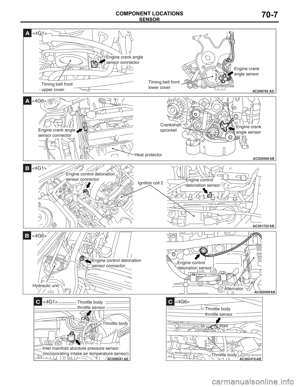
AC208762
A
AD
Timing belt front
upper coverTiming belt front
lower coverEngine crank
angle sensor
<4G1>
Engine crank angle
sensor connector
AC302008
A<4G6>
ABHeat protector
Crankshaft
sprocket
Engine crank angle
sensor connectorEngine crank
angle sensor
AC301752
B
AB
Ignition coil 2
<4G1>
Engine control detonation
sensor connector
Engine control
detonation sensor
AC302009
B
AB
Hydraulic unit
<4G6>
Alternator
Engine control detonation
sensor connectorEngine control
detonation sensor
AC208541
C
AE
<4G1>
Throttle body
Throttle body
throttle sensor
Inlet manifold absolute pressure sensor
(incorporating intake air temperature sensor)
AC302479
AB
C
Throttle body
<4G6>
Throttle body
throttle sensor
SENSOR
COMPONENT LOCA TIONS70-7
Page 398 of 800
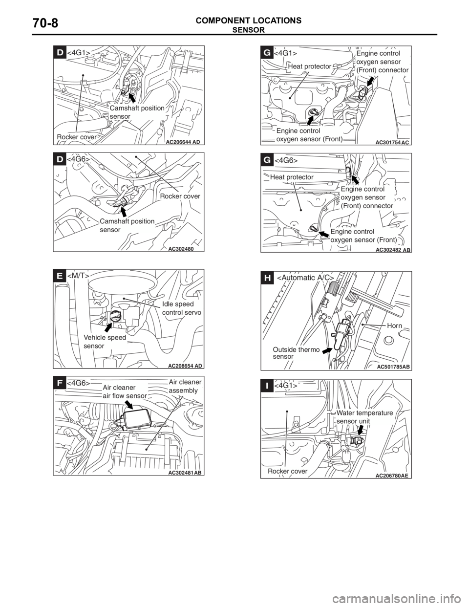
AC206644AD
Camshaft position
sensor
D<4G1>
Rocker cover
AC302480AB
D
Camshaft position
sensor
Rocker cover
<4G6>
AC208654
AD
E
Vehicle speed
sensor
Idle speed
control servo
AC302481AB
FAir cleaner
assembly<4G6>Air cleaner
air flow sensor
AB
AC301754
G<4G1>
AC
Heat protector
Engine control
oxygen sensor (Front)
Engine control
oxygen sensor
(Front) connector
AC302482
G
AB
Heat protector
<4G6>
Engine control
oxygen sensor
(Front) connector
Engine control
oxygen sensor (Front)
AC501785AB
H
Horn
Outside thermo
sensor
AC206780 AE
I
Rocker cover
<4G1>
Water temperature
sensor unit
SE
NSOR
COMPONENT LOCA TIONS70-8
Page 400 of 800
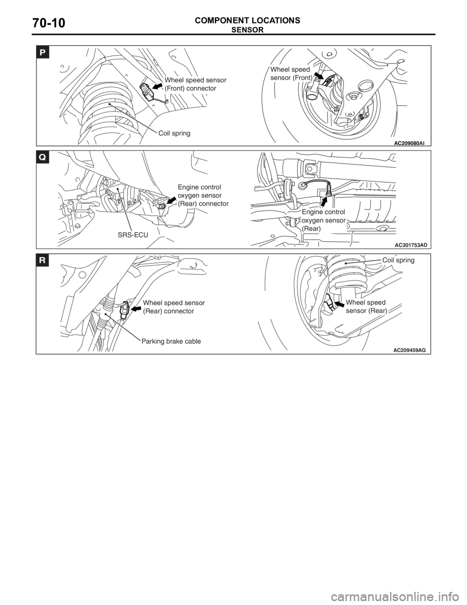
AC209080
P
AI
Wheel speed sensor
(Front) connector
Coil spring
Wheel speed
sensor (Front)
AC301753AD
SRS-ECU
Q
Engine control
oxygen sensor
(Rear) connector
Engine control
oxygen sensor
(Rear)
AC209459
R
Wheel speed sensor
(Rear) connector
Parking brake cable
Coil spring
AG
Wheel speed
sensor (Rear)
SE NSOR
COMPONENT LOCA TIONS70-10