check oil MITSUBISHI LANCER 2006 User Guide
[x] Cancel search | Manufacturer: MITSUBISHI, Model Year: 2006, Model line: LANCER, Model: MITSUBISHI LANCER 2006Pages: 800, PDF Size: 45.03 MB
Page 91 of 800
AK202734
STARTING SYSTEM
ENGINE ELECTRICAL16-29
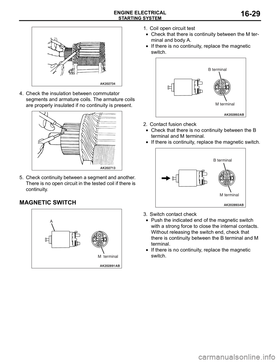
4. Check t he in sulation between commut ator
segment s an d arma ture coils. Th e armature coils
are prope rly insu lated if no con t inuity is pre s ent .
AK202713
5. Check continuit y bet ween a segment and another .
Th ere is n o ope n circui t in th e t e s t e d c o il if t h e r e is
continuity .
MA GNETIC SW ITCH
AK202891
A
M terminal
AB
1.Coil ope n circuit test
•Check that there is continuity be twe en the M te r-
minal and body A.
•
AK202892
M terminal
B terminal
AB
If th
ere is no continuit y , replace t he ma gnetic
sw
itc h .
2.Cont act fusion check
•Check that there is no co ntinu i ty between the B
termina
l and M te rmin al.
•
AK202893
M terminal
B terminal
AB
If th
ere is co ntinu i ty , re place the magn etic switch.
3.Switch cont act check
•Push the indicated end o f the magne tic switch
with
a stro ng force to close th e inte rnal cont act s .
Without re
leasing the switch end, check tha t
the
r e is con t inuity b e tween th e B terminal and M
termina
l .
•If there is no continuit y , replace t he ma gnetic
sw
itc h .
Page 94 of 800
IGNITION SYSTEM
ENGINE ELECTRICAL16-32
ON-VEHICLE SERVICE
IGNITION COIL (WITH BUILT-IN POWER
TRANSISTOR) CHECK
M1163001200324
Check by the following procedure, and replace if
there is a malfunction.
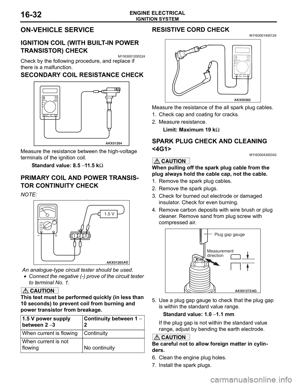
SECONDARY COIL RESISTANCE CHECK
AKX01264
Measure the resist ance bet we en the high- volt ag e
terminals of th
e ign i tio n coil.
St andard va lue: 8.5 − 11 .5 kΩ
PRIM AR Y COIL AND POWER TRANSIS-
TO R CONTINUITY CHECK
NO TE: .•
AKX01265 AD
1.5 V
1 23
+
–
An analogue-t y pe circuit t e ster shou ld be use d .
•Connect the n egative (-) pro v e of the circuit t e ster
to t
e rminal No. 1.
CAUTION
This test must be performed quickly (in less than
10 seconds) to prevent coil from burning and
power transistor from breakage.
1.5 V power supply
between 2
− 3
Continuity between 1 −
2
When current is flowingContinuity
When current is not
flowing
No continuity
RESISTIVE CORD CHECK
M1163001400124
AKX00382
Measure the resistance of the all spark plug cables.
1. Check cap and coating for cracks.
2. Measure resistance.
Limit: Maximum 19 kΩ
SPARK PLUG CHECK AND CLEANING
<4G1>
M1163004300342
CAUTION
When pulling off the spark plug cable from the
plug always hold the cable cap, not the cable.
1. Remove the spark plug cables.
2. Remove the spark plugs.
3. Check for burned out electrode or damaged insulator. Check for even burning.
4. Remove carbon deposits with wire brush or plug cleaner. Remove sand from plug screw with
compressed air.
AKX01272 AG
Plug gap gauge
Measurement
direction
5. Use a plug gap gauge to check that the plug gap is within the standard value range.
Standard value: 1.0 − 1.1 mm
If the plug gap is not within the standard value
range, adjust by bending the earth electrode.
CAUTION
Be careful not to allow foreign matter in cylin-
ders.
6. Clean the engine plug holes.
7. Install the spark plugs.
Page 99 of 800
IGNITION SYSTEM
ENGINE ELECTRICAL16-37
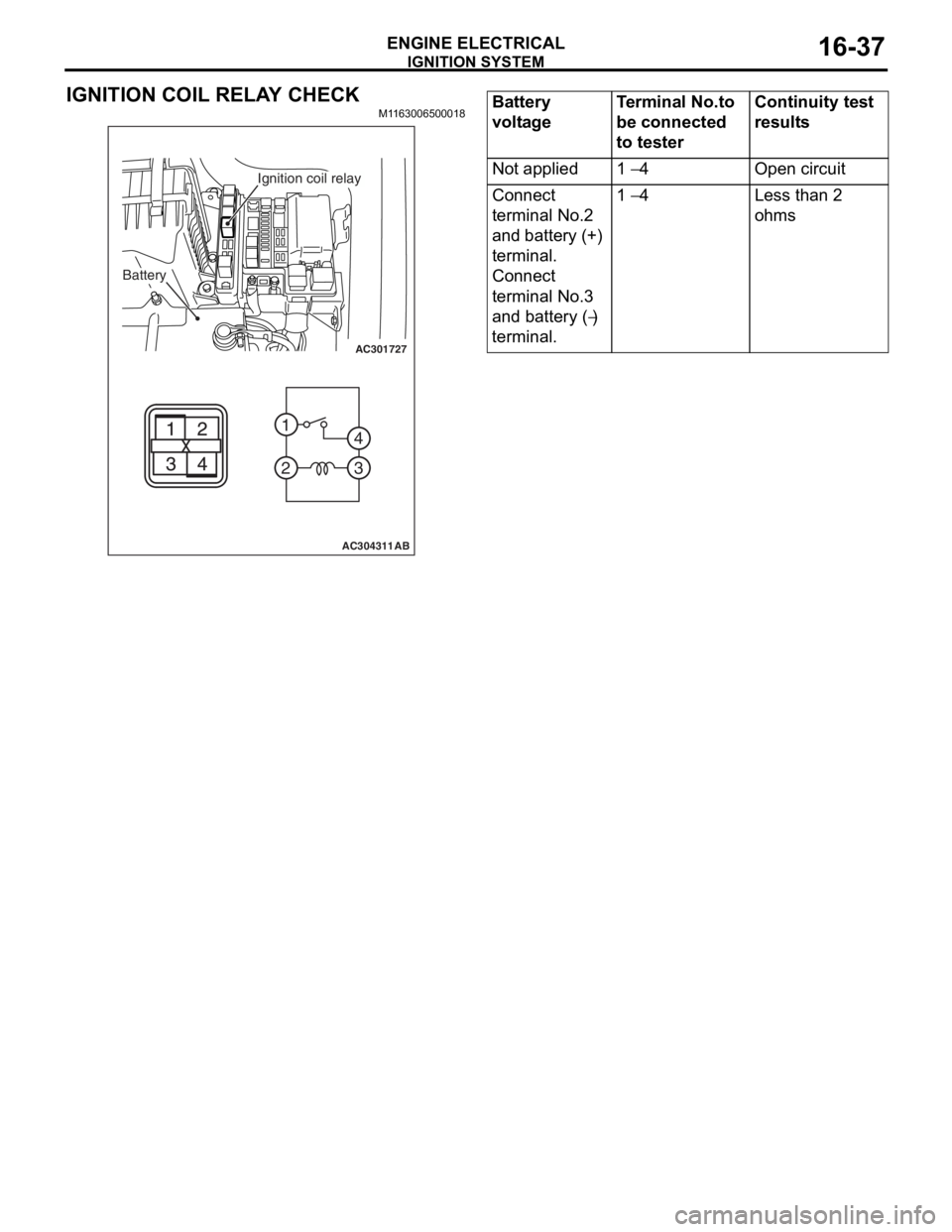
IGNITION COIL RELAY CHECK
M1163006500018
AC301727
2 1
3
4
AC304311AB
Battery
Ignition coil relay
Battery
voltageTerminal No.to
be connected
to testerContinuity test
results
Not applied1 − 4Open circuit
Connect
terminal No.2
and battery (+)
terminal.
Connect
terminal No.3
and battery (
−)
terminal.
1 − 4Less than 2
ohms
Page 144 of 800
FRONT AXLE HUB ASSEMBLY
FRONT AXLE26-12
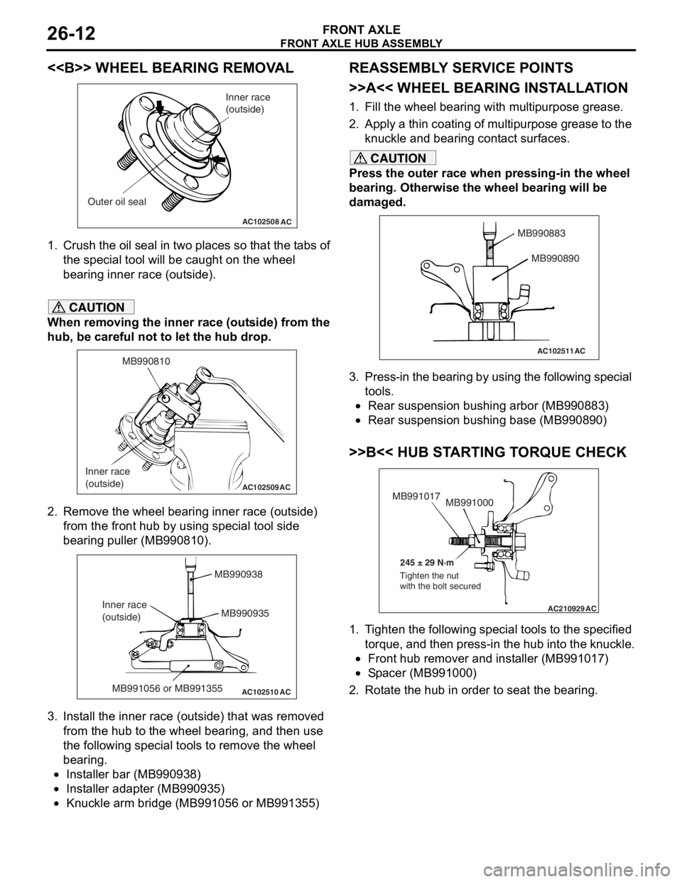
<> WHEEL BEARING REMOVAL
AC102508AC
Inner race
(outside)
Outer oil seal
1. Crush th e oil seal in two pl ace s so t hat t he t abs of
th e spe c ia l too l will be caugh t on th e wheel
be aring inne r race (out side).
CAUTION
When removing the inner race (outside) from the
hub, be careful not to let the hub drop.
AC102509
MB990810
Inner race
(outside)
AC
2. Remove the wheel bearing inner race (outside) from the front hub by using special tool side
bearing puller (MB990810).
AC102510 AC
MB990938
MB990935
MB991056 or MB991355
Inner race
(outside)
3. Install the inner race (outside) that was removed
from the hub to the wheel bearing, and then use
the following special tools to remove the wheel
bearing.
•Installer bar (MB990938)
•Installer adapter (MB990935)
•Knuckle arm bridge (MB991056 or MB991355)
REASSEMBLY SERVICE POINTS
>>A<< WHEEL BEARING INSTALLATION
1. Fill the wheel bearing with multipurpose grease.
2. Apply a thin coating of multipurpose grease to the knuckle and bearing contact surfaces.
CAUTION
Press the outer race when pressing-in the wheel
bearing. Otherwise the wheel bearing will be
damaged.
AC102511
MB990883
MB990890
AC
3. Press-in the bearing by using the following special tools.
•Rear suspension bushing arbor (MB990883)
•Rear suspension bushing base (MB990890)
>>B<< HUB STARTING TORQUE CHECK
AC210929AC
MB991000
MB991017
245 ± 29 N·m
Tighten the nut
with the bolt secured
1. Tighten the following special tools to the specified torque, and then press-in the hub into the knuckle.
•Front hub remover and installer (MB991017)
•Spacer (MB991000)
2. Rotate the hub in order to seat the bearing.
Page 146 of 800
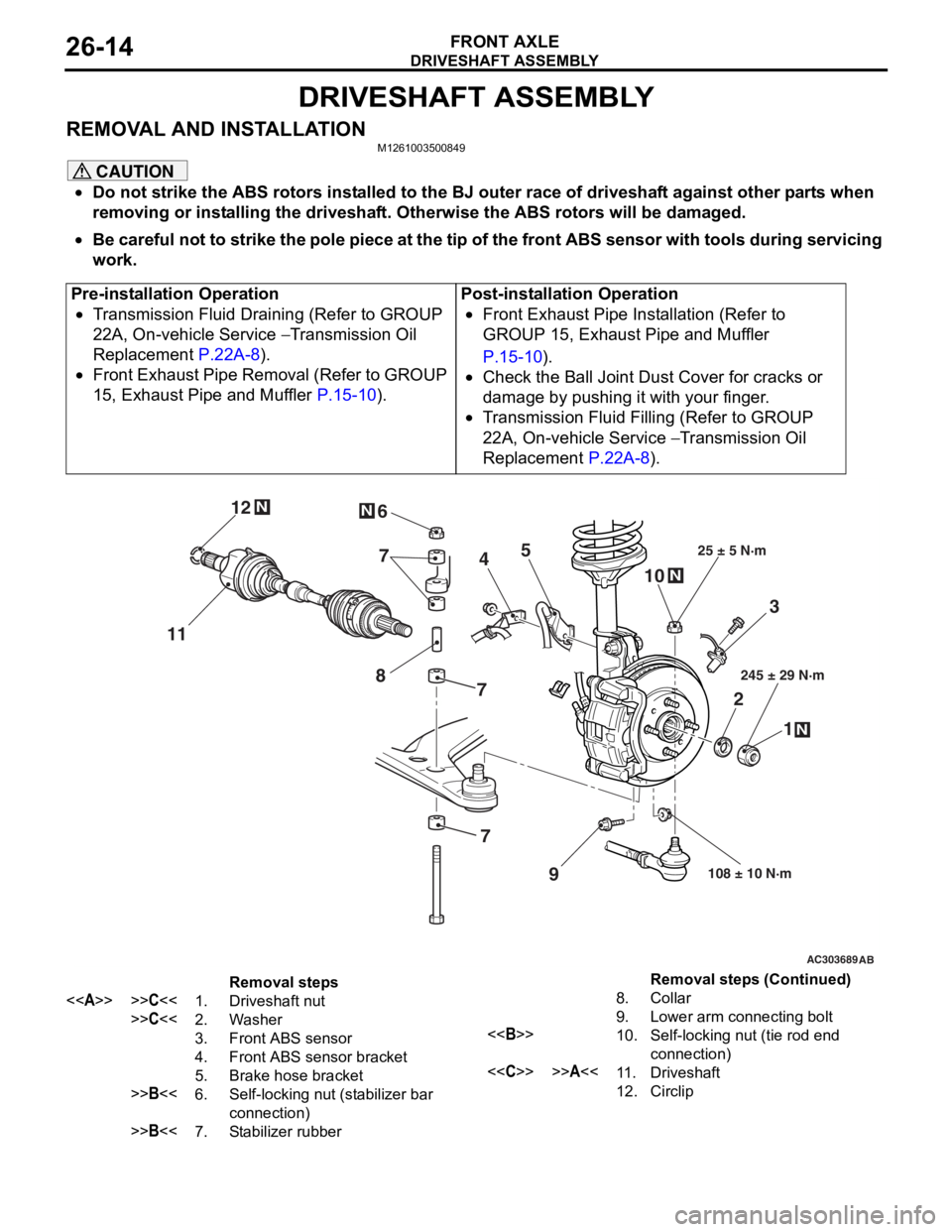
DRIVESHAFT ASSEMBLY
FRONT AXLE26-14
DRIVESHAFT ASSEMBLY
REMOVAL AND INSTALLATIONM1261003500849
CAUTION
•Do not strike the ABS rotors installed to the BJ outer race of driveshaft against other parts when
removing or installing the driveshaft. Otherwise the ABS rotors will be damaged.
•
Pre-installation Operation
•Transmission Fluid Draining (Refer to GROUP
22A, On-vehicle Service
− Transmission Oil
Replacement
P.22A-8).
•Front Exhaust Pipe Removal (Refer to GROUP
15, Exhaust Pipe and Muffler
P.15-10).
Post-installation Operation
•Front Exhaust Pipe Installation (Refer to
GROUP 15, Exhaust Pipe and Muffler
P.15-10).
•Check the Ball Joint Dust Cover for cracks or
damage by pushing it with your finger.
•Transmission Fluid Filling (Refer to GROUP
22A, On-vehicle Service
− Transmission Oil
Replacement
P.22A-8).
AC303689AB
9
N
N
NN
10
7
4
3
2 1
25 ± 5 N·m
245 ± 29 N·m
108 ± 10 N·m
8
5
6
11 12
77
Removal steps
<>>>C<<1.Driveshaft nut
>>C<<2.Washer
3.Front ABS sensor
4.Front ABS sensor bracket
5.Brake hose bracket
>>B<<6.Self-locking nut (stabilizer bar
connection)
>>B<<7.Stabilizer rubber
8.Collar
9.Lower arm connecting bolt
<>10.Self-locking nut (tie rod end
connection)
<
12.Circlip
Be careful not to strike the pole piece at the tip of the front ABS sensor with tools during servicing
work.
Removal steps (Continued)
Page 162 of 800
REAR AXLE HUB ASSEMBLY
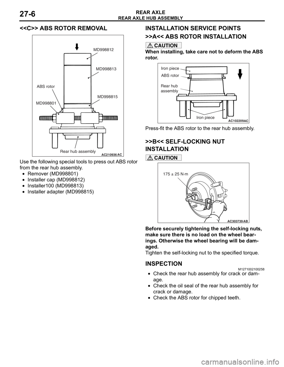
REAR AXLE27-6
<
AC210936AC
MD998815
MD998801 MD998813
MD998812
Rear hub assembly
ABS rotor
Use
the fo llowing specia l to ols t o press o u t ABS rot o r
from th
e rear h ub assembly .
•Remover (MD99880 1)
•Insta lle r cap (MD9988 12)
•Insta lle r100 (MD9 98813 )
•Insta lle r adapte r (MD998 815)
INSTALLA T ION SER VICE POINTS
>>A<< ABS ROTO R INST ALLA TION
CAUTION
When installing, take care not to deform the ABS
rotor.
AC102209
Iron piece
ABS rotor
Rear hub
assembly
Iron piece
AC
Press-fit the ABS rotor to the rear hub assembly.
>>B<< SELF-LOCKING NUT
INSTALLATION
AC303739
175 ± 25 N·m
AB
CAUTION
Before securely tightening the self-locking nuts,
make sure there is no load on the wheel bear
-
ings. Otherwise the wheel bearing will be dam-
aged.
Tighten the self-locking nut to the specified torque.
INSPECTIONM1271002100258
•Check the rear hub assembly for crack or dam-
age.
•Check the oil seal of the rear hub assembly for
crack or damage.
•Check the ABS rotor for chipped teeth.
Page 186 of 800
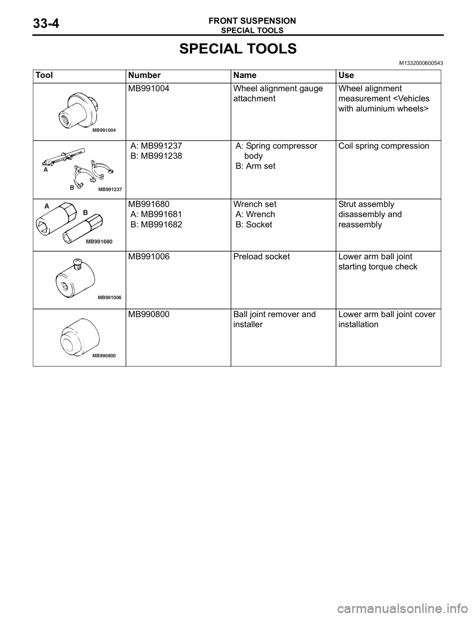
SPECIAL TOOLS
FRONT SUSPENSION33-4
SPECIAL TOOLS
M1332000600543
ToolNumberNameUse
MB991004
MB991004Wheel alignme n t gau ge
att
a chmentWheel alig nme n t
measurement
with aluminium wheels>
MB991237
A
B
A: MB9912 37
B: MB991238
A: Sp ring compressor
b ody
B: Arm set
Coil spring compression
MB991680
A BMB991680
A: MB9916 81
B: MB991682
Wr ench set
A: W r ench
B: Socket
Str u t a s s e m b l y
d
i sa ssembly an d
reassembly
MB991006
MB991006Prel oad socketLo wer arm ball joint
st
arting torque check
MB990800
MB990800Ball j o int remo ver an d
inst
al lerLo wer arm ball joint cover
inst
allation
Page 189 of 800
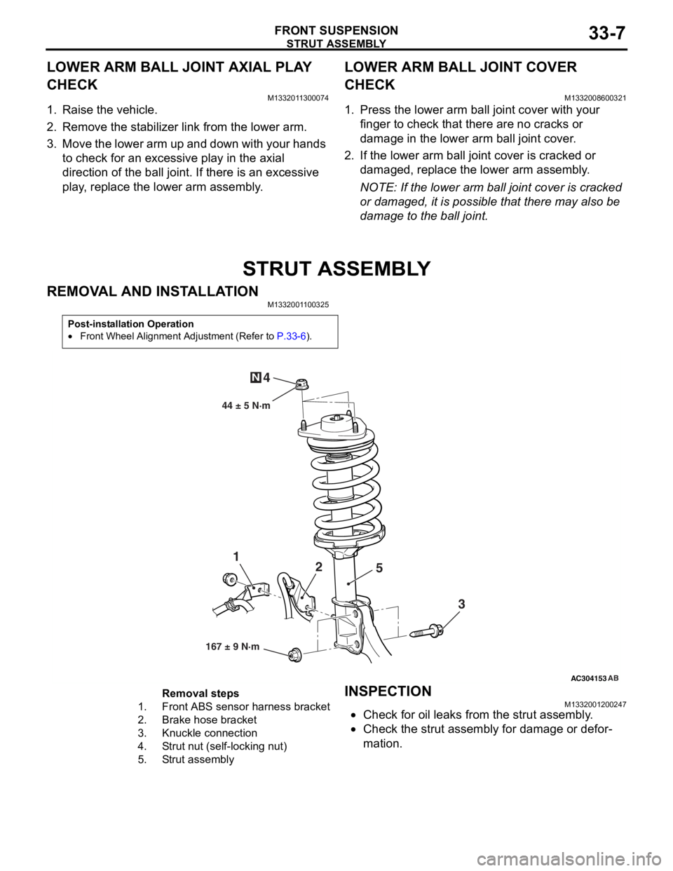
STRUT ASSEMBLY
FRONT SUSPENSION33-7
LOWER ARM BALL JOINT AXIAL PLAY
CHECK
M1332011300074
1. Raise the vehicle.
2. Remove the stabilizer link from the lower arm.
3. Move the lower arm up and down with your hands to check for an excessive play in the axial
direction of the ball joint. If there is an excessive
play, replace the lower arm assembly.
LOWER ARM BALL JOINT COVER
CHECK
M1332008600321
1. Press the lower arm ball joint cover with your finger to check that there are no cracks or
damage in the lower arm ball joint cover.
2. If the lower arm ball joint cover is cracked or damaged, replace the lower arm assembly.
NOTE: If the lower arm ball joint cover is cracked
or damaged, it is possible that there may also be
damage to the ball joint.
STRUT ASSEMBLY
REMOVAL AND INSTALLATION
M1332001100325
Post-installation Operation
•Front Wheel Alignment Adjustment (Refer to P.33-6).
AC304153
44 ± 5 N·m
1 2
3
4
N
AB
167 ± 9 N·m
5
Removal steps
1.Front ABS sensor
harness bracket
2.Brake hose bracket
3.Knuckle connection
4.Strut nut (self-locking nut)
5.Strut assembly
INSPECTION
M13320012 0024 7
•Check for oil leaks fro m the stru t assemb ly .
•Check the stru t assemb ly for damage o r defor-
mation.
Page 192 of 800
STRUT ASSEMBLY
FRONT SUSPENSION33-10
>>B<< STRUT NUT (SELF-LOCKING NUT)
INSTALLATION
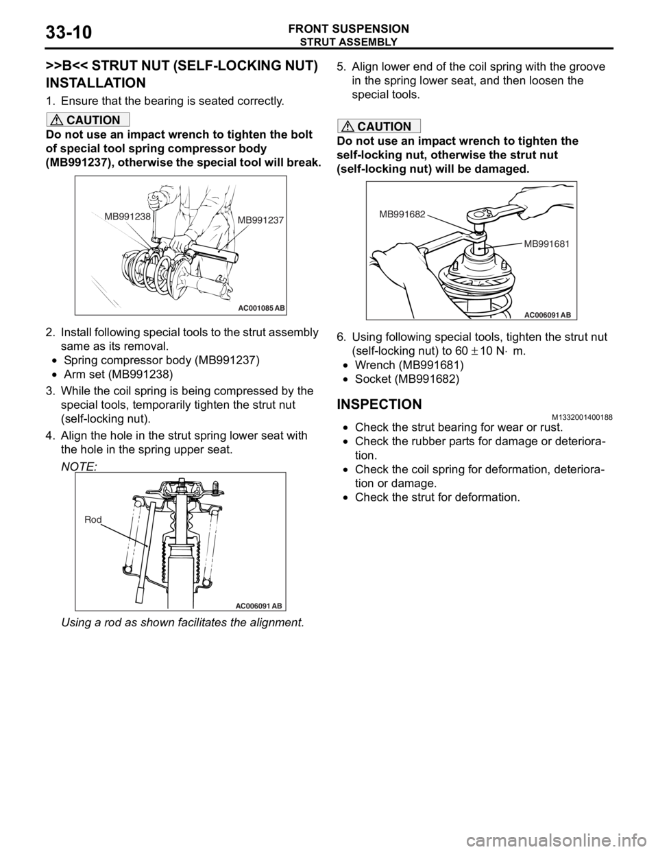
1. Ensure that the bearing is seated correctly.
CAUTION
Do not use an impact wrench to tighten the bolt
of special tool spring compressor body
(MB991237), otherwise the special tool will break.
AC001085 AB
MB991238MB991237
2. Install following special tools to the strut assembly
same as its removal.
•Spring compressor body (MB991237)
•Arm set (MB991238)
3. While the coil spring is being compressed by the
special tools, temporarily tighten the strut nut
(self-locking nut).
4. Align the hole in the strut spring lower seat with the hole in the spring upper seat.
NOTE:
AC006091 AB
Rod
Using a rod as shown fa cilitates the alignment.
5. Align lower end of the coil spring with the groove
in the spring lower seat, and then loosen the
special tools.
CAUTION
Do not use an impact wrench to tighten the
self-locking nut, otherwise the strut nut
(self-locking nut) will be damaged.
AC006091 AB
MB991681
MB991682
6. Using following special tools, tighten the strut nut
(self-locking nut) to 60
± 10 N⋅m.
•Wrench (MB991681)
•Socket (MB991682)
INSPECTIONM1332001400188
•Check the strut bearing for wear or rust.
•Check the rubber parts for damage or deteriora-
tion.
•Check the coil spring for deformation, deteriora-
tion or damage.
•Check the strut for deformation.
Page 213 of 800
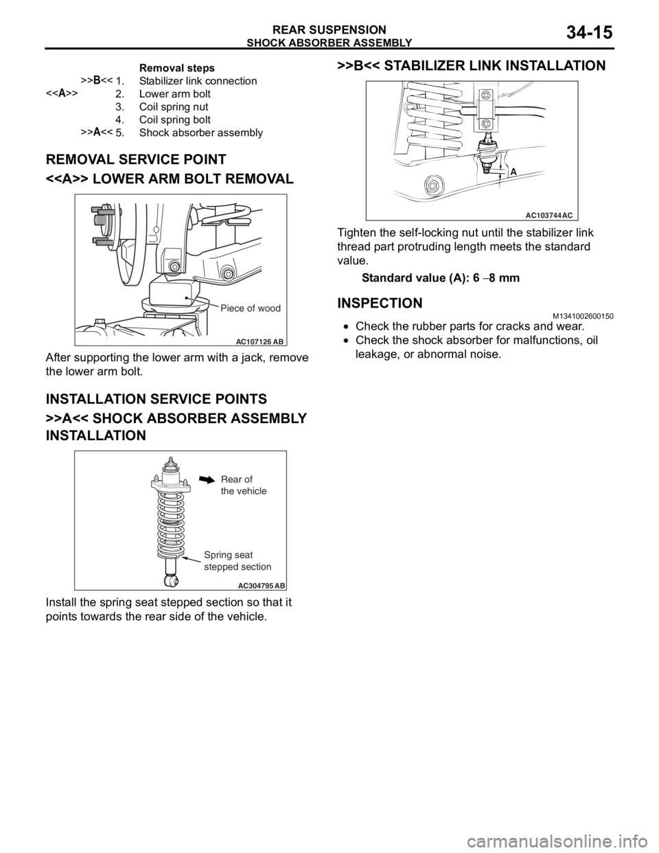
Removal steps
>>B<<1.Stabilizer link connection
<>2.Lower arm bolt
3.Coil spring nut
4.Coil spring bolt
>>A<<5.Shock absorber assembly
SHOCK ABSORBER ASSEMBLY
REAR SUSPENSION34-15
REMOVAL SERVICE POINT
<> LOWER ARM BOLT REMOVAL
AC107126AB
Piece of wood
After suppo rting the lo we r arm with a jack, remove
the lo
we r arm b o lt.
INSTALLA T ION SER VICE POINT S
>>A<< SHOCK ABSORBER ASSEMBL Y
INST
ALLA TION
AC304795 AB
Spring seat
stepped section
Rear of
the vehicle
Install the sprin g se at ste pped section so th at it
point
s towards the rea r side of th e ve hicle.
>>B<< STABILIZER LINK INST ALLA TION
AC103744
A
AC
Ti ghten the self-locking nut un til t he st ab ilizer link
thread
p a rt protrud i ng length mee t s the st a ndard
value.
St andard va lue (A): 6 − 8 mm
INSPECTIONM13410026 0015 0
•Check the rubbe r p a rt s for cracks a nd wear .
•Check the sho c k abso r ber for malfunct i ons, oil
le
akag e, or a bnormal no ise .