gasket MITSUBISHI LANCER 2006 User Guide
[x] Cancel search | Manufacturer: MITSUBISHI, Model Year: 2006, Model line: LANCER, Model: MITSUBISHI LANCER 2006Pages: 800, PDF Size: 45.03 MB
Page 61 of 800
AC303695AC
1
3
50 ± 10 N·m
2
7
N
N
45
8 4
N9
10
59 ± 10 N·m
45 ± 5 N·m
13 ± 2 N·m
45 ± 5 N·m
13 ± 2 N·m
10
<4G6-M/T>
AC504798AB
<4G6-A/T> 1
2
3N
4
7N8
N9
10
13 ± 2 N·m
13 ± 2 N·m
45 ± 5 N·m
59 ± 10 N·m
6N
10
4
50 ± 10 N·m
13 ± 2 N·m
13 ± 2 N·m
50 ± 10 N·m
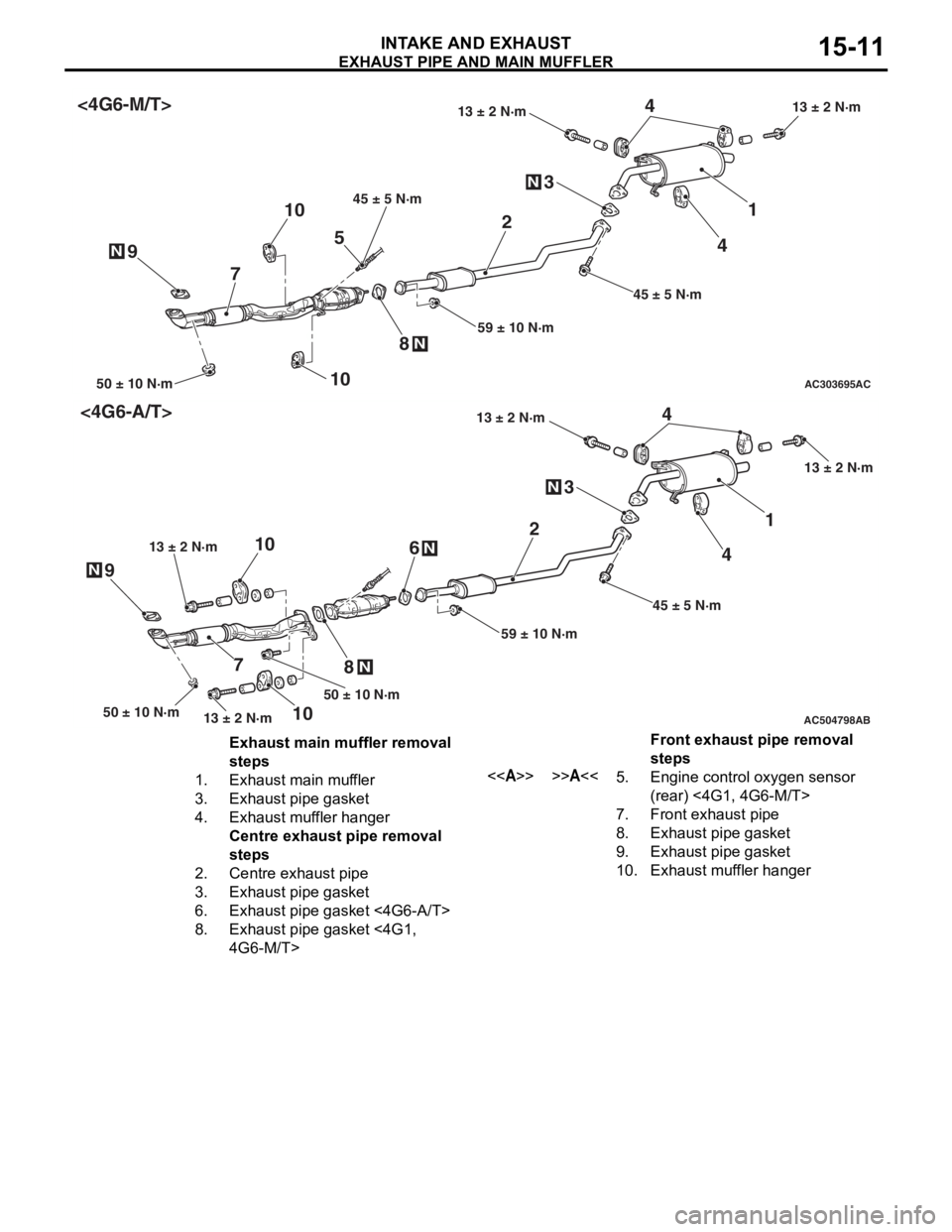
Exhaust main muffler removal
steps
1.Exhaust main muffler
3.Exhaust pipe gasket
4.Exhaust muffler hanger
Centre exhaust pipe removal
steps
2.Centre exhaust pipe
3.Exhaust pipe gasket
6.Exhaust pipe gasket <4G6-A/T>
8.Exhaust pipe gasket <4G1,
4G6-M/T>
Front exhaust pipe removal
steps
<>>>A<<5.Engine control oxygen sensor
(rear) <4G1, 4G6-M/T>
7.Front exhaust pipe
8.Exhaust pipe gasket
9.Exhaust pipe gasket
10.Exhaust muffler hanger
EX HAUS T PIPE AND MAIN MU FFLER
INTAKE AN D EXHAU ST15-11
Page 85 of 800
STARTING SYSTEM
ENGINE ELECTRICAL16-23
STARTER MOTOR ASSEMBLY INSPECTION
M1162001100205
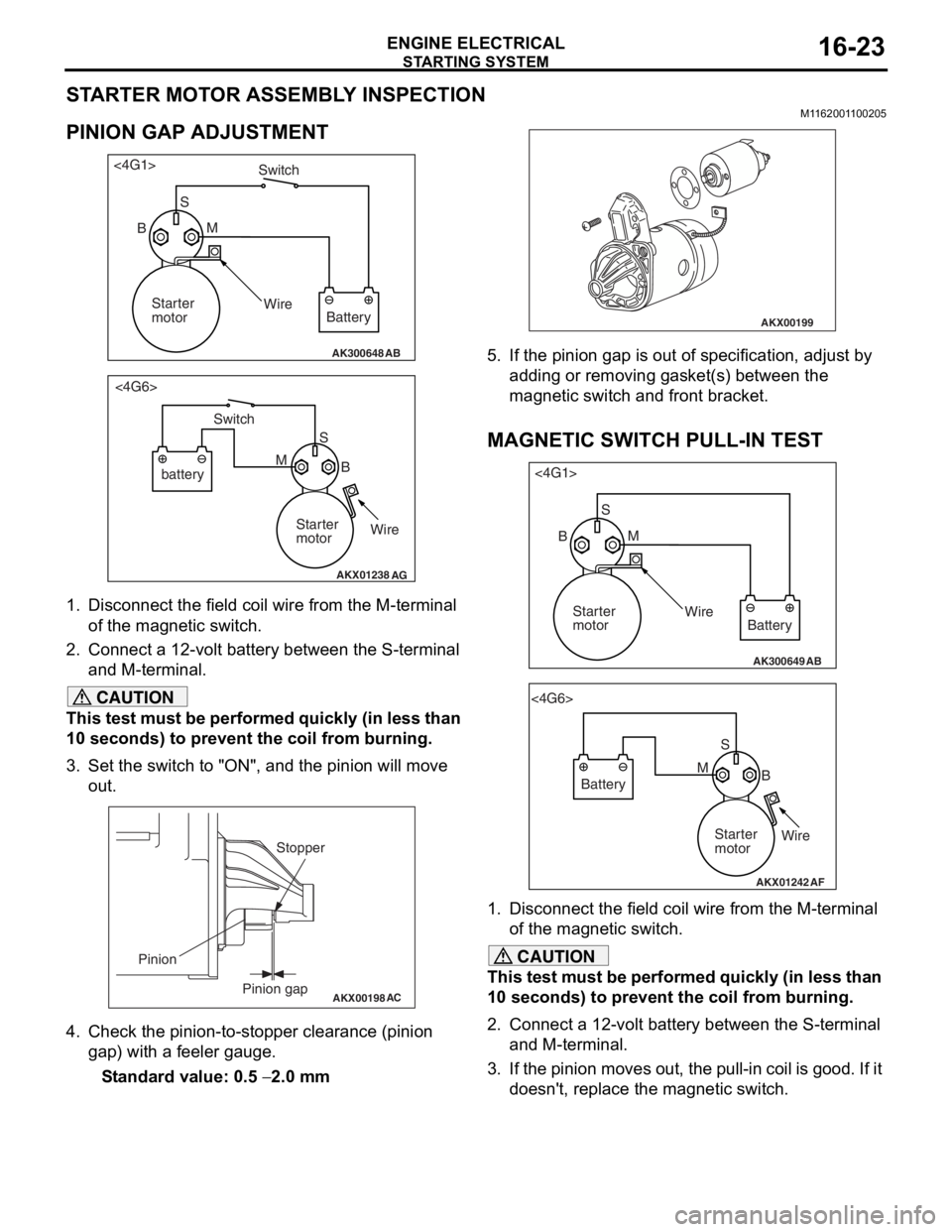
PINION GAP ADJUSTMENT
AK300648AB
<4G1>
Switch
S M
Wire Battery
Starter
motor
B
AKX01238
<4G6>
B
M S
battery Switch
Starter
motorWire
AG
1.
Disco nnect the field coil wire f r om th e M-te rmin al
of the magnet ic switch.
2.Conn ect a 12-volt b a ttery between the S-termina l
an d M-t e rminal.
CAUTION
This test must be performed quickly (in less than
10 seconds) to prevent the coil from burning.
3. Set the switch to "ON", and the pinion will move out.
AKX00198
Stopper
Pinion gap
Pinion
AC
4. Check the pinion-to-stopper clearance (pinion
gap) with a feeler gauge.
Standard value: 0.5 − 2.0 mm
AKX00199
5. If the pinion gap is out of specification, adjust by adding or removing gasket(s) between the
magnetic switch and front bracket.
MAGNETIC SWITCH PULL-IN TEST
AK300649AB
<4G1>
SM
Wire Battery
Starter
motor
B
AKX01242
<4G6>
SB
M
Battery
Starter
motorWire
AF
1. Disconnect the field coil wire from the M-terminal
of the magnetic switch.
CAUTION
This test must be performed quickly (in less than
10 seconds) to prevent the coil from burning.
2. Connect a 12-volt battery between the S-terminal and M-terminal.
3. If the pinion moves out, the pull-in coil is good. If it doesn't, replace the magnetic switch.
Page 122 of 800
EMISSION CONTROL
ENGINE AND EMISSION CONTROL17-16
5. Replace the gasket, and tighten to the specified torque.
Tightening torque:
<4G1> 21 ± 4 N⋅m
<4G6> 20 ± 2 N⋅m
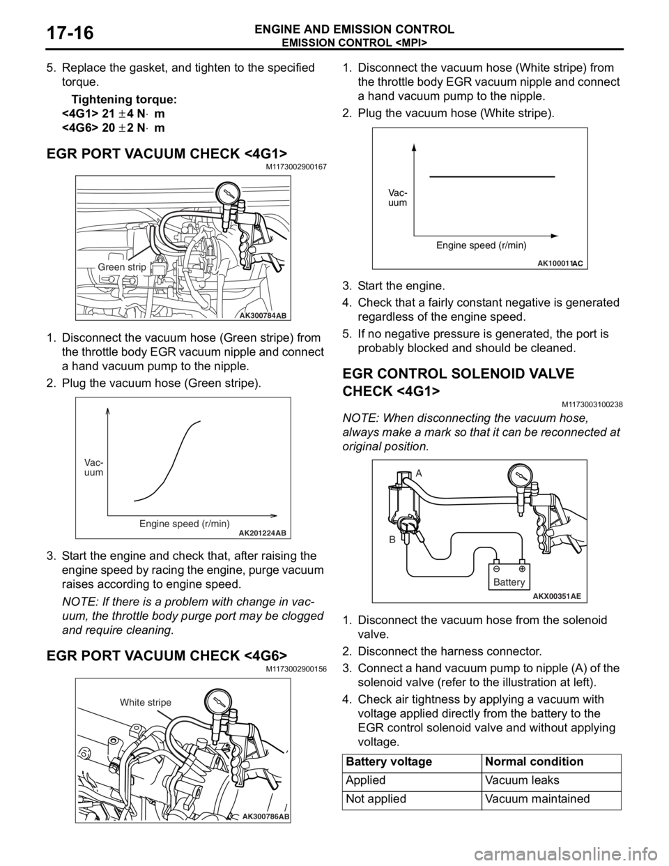
EGR PORT VACUUM CHECK <4G1>M1173002900167
AK300784AB
Green strip
1.Disco nnect the vacu um ho se (Green stripe) from
th e t h ro tt le b o d y EGR va cuu m ni pp le an d co nn ec t
a hand vacu um p u mp to the nipple.
2.Plu g the vacuum hose (Gree n stripe).
AK201224AB
Vac-
uum
Engine speed (r/min)
3.S t art the engin e and check t hat, af ter ra ising th e
engine spe ed by ra cin g the e ngine, p u rge vacuu m
raises according to engine speed.
NOTE: If ther e is a prob lem with change in vac-
uum, the t h rottle bod y p u rge port may be clo gged
an
d requ ire clean ing.
EGR PORT VA CUUM CHECK <4G6>M1173 0029 0015 6
AK300786AB
White stripe
1.Disco nnect the vacu um h o se (W hite strip e ) from
th e t h ro tt le b o d y EGR va cuu m ni pp le an d co nn ec t
a hand vacuum p u mp to the nipple.
2.Plug the vacuum hose (White stripe).
AK100011AC
Vac-
uum
Engine speed (r/min)
3.S t art the engine.
4.Check that a fairly const a nt n egative is gene rated
re gardle s s of the engine sp eed.
5.If no neg ative pressur e is genera t ed, th e port is
p r obably blocked an d sh ould be cleane d.
EGR CONTROL SOLENOID VA L V E
CHECK <
4 G1 >
M1173 0031 0023 8
NOTE: Whe n discon nect i ng th e va cuum hose,
always make a mark so th at it can be reconnected at
original p o sition.
AKX00351
A
B
AE
Battery
1. Disco nnect the vacu um h o se f r om th e solenoid
valve.
2.Disco nnect the ha rness connector .
3.Con nect a ha nd vacu um pump to nipp le (A) of the
solen o id valve (ref e r to th e ill ust r ation at le f t ).
4.Check a i r tightness b y ap plying a vacuum with
volt age applied d i rectly from t he batt e ry to the
EGR cont rol solen o id valve and withou t applyin g
volt age .
Battery voltageNormal condition
AppliedVa c u u m l e a k s
Not appliedVacuum maintained
Page 124 of 800
EMISSION CONTROL
ENGINE AND EMISSION CONTROL17-18
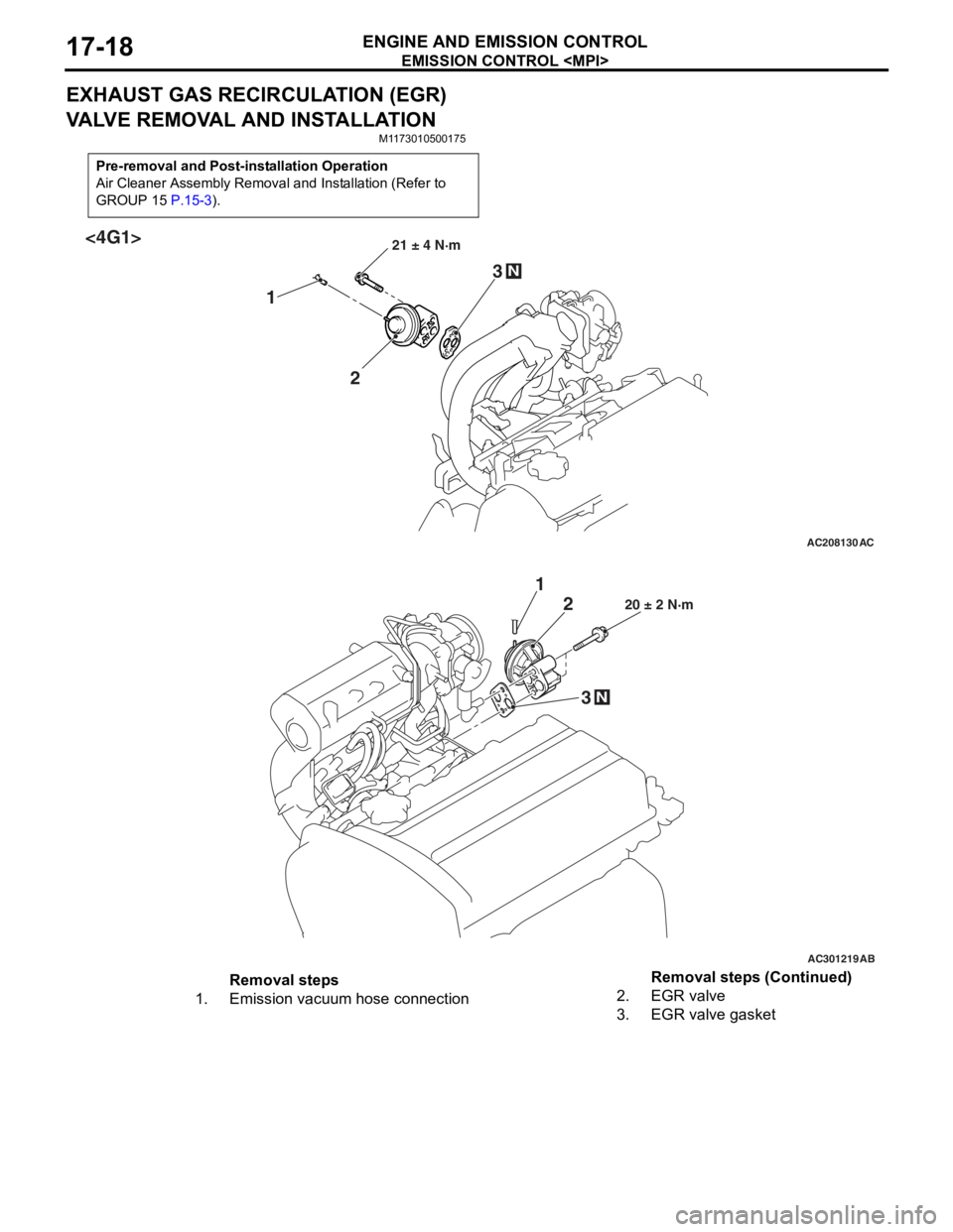
EXHAUST GAS RECIRCULATION (EGR)
VALVE REMOVAL AND INSTALLATION
M1173010500175
Pre-removal and Post-installation Operation
Air Cleaner Assembly Removal and Installation (Refer to
GROUP 15
P.15-3).
AC208130
21 ± 4 N·m
2
1
3
N
AC
<4G1>
AC301219
20 ± 2 N·m2
1
3
N
AB
Removal steps
1.Emission vacuum hose connection2.EGR valve
3.EGR valve gasket
Removal steps (Continued)
Page 125 of 800
EMISSION CONTROL
ENGINE AND EMISSION CONTROL17-19
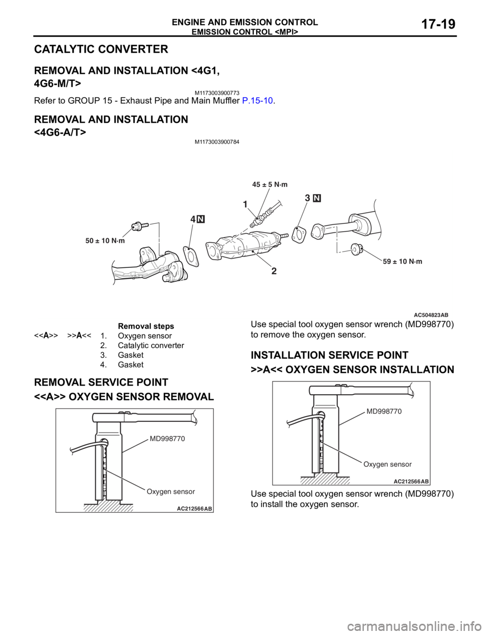
CATALYTIC CONVERTER
REMOVAL AND INSTALLATION <4G1,
4G6-M/T>
M1173003900773
Refer to GROUP 15 - Exhaust Pipe and Main Muffler P.15-10.
REMOVAL AND INSTALLATION
<4G6-A/T>
M1173003900784
AC504823
2
3N
N4
59 ± 10 N·m
50 ± 10 N·m
1
45 ± 5 N·m
AB
Removal steps
<>>>A<<1.Oxygen sensor
2.Catalytic converter
3.Gasket
4.Gasket
REMOVA L SER V ICE POINT
<> OXYGEN SENSOR REMOV A L
AC212566AB
MD998770
Oxygen sensor
Use spec ia l tool oxyg en sen s or wrench (MD9987 70)
to remove
the oxyge n sen s or .
INSTALLA T ION SER VICE POINT
>>A<< OXYGEN SENSOR INST ALL A TION
AC212566AB
MD998770
Oxygen sensor
Use spec ia l tool oxyg en sen s or wrench (MD9987 70)
to inst
all the oxyge n sen s or .
Page 179 of 800
CROSSMEMBER
POWER PLANT MOUNT32-9
AC304000
108 ± 10 N·m25 ± 4 N·m 18 ± 2 N·m
70 ± 10 N·m
21 ± 4 N·m
21 ± 4 N·m
186 ± 10 N·m* 167 ± 9 N·m49 ± 10 N·m
52 ± 7 N·m* 45 ± 5 N·m*
70 ± 10 N·m
57 ± 7 N·m
12 ± 2 N·m
5
4
10
9
11
8
12
1413
6
7 16
15
17 2
3
1
N
N
N
2
1 1
AB
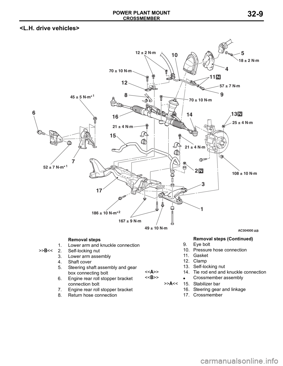
Removal steps
1.Lower arm and knuckle connection
>>B<<2.Self-locking nut
3.Lower arm assembly
4.Shaft cover
5.Steering shaft assembly and gear
box connecting bolt
6.Engine rear roll stopper bracket
connection bolt
7.Engine rear roll stopper bracket
8.Return hose connection
9.Eye bolt
10.Pressure hose connection
11 .Gasket
12.Clamp
13.Self-locking nut
<>14.Tie rod end and knuckle connection
<>•Crossmember assembly
>>A<<15.Stabilizer bar
16.Steering gear and linkage
17.Crossmember
Removal steps (Continued)
Page 180 of 800
CROSSMEMBER
POWER PLANT MOUNT32-10
AC101614
12
3
4
5
6 7
8
9
10
11
12
13 14
15
16
45 ± 5 N·m*¹
52 ± 7 N·m*¹ 186 ± 10 N·m*²167 ± 9 N·m
49 ± 10 N·m 108 ± 10 N·m25 ± 4 N·m
21 ± 4 N·m 70 ± 10 N·m
5.0 ± 1.0 N·m
18 ± 2 N·m
57 ± 7 N·m
N
N
N
AE
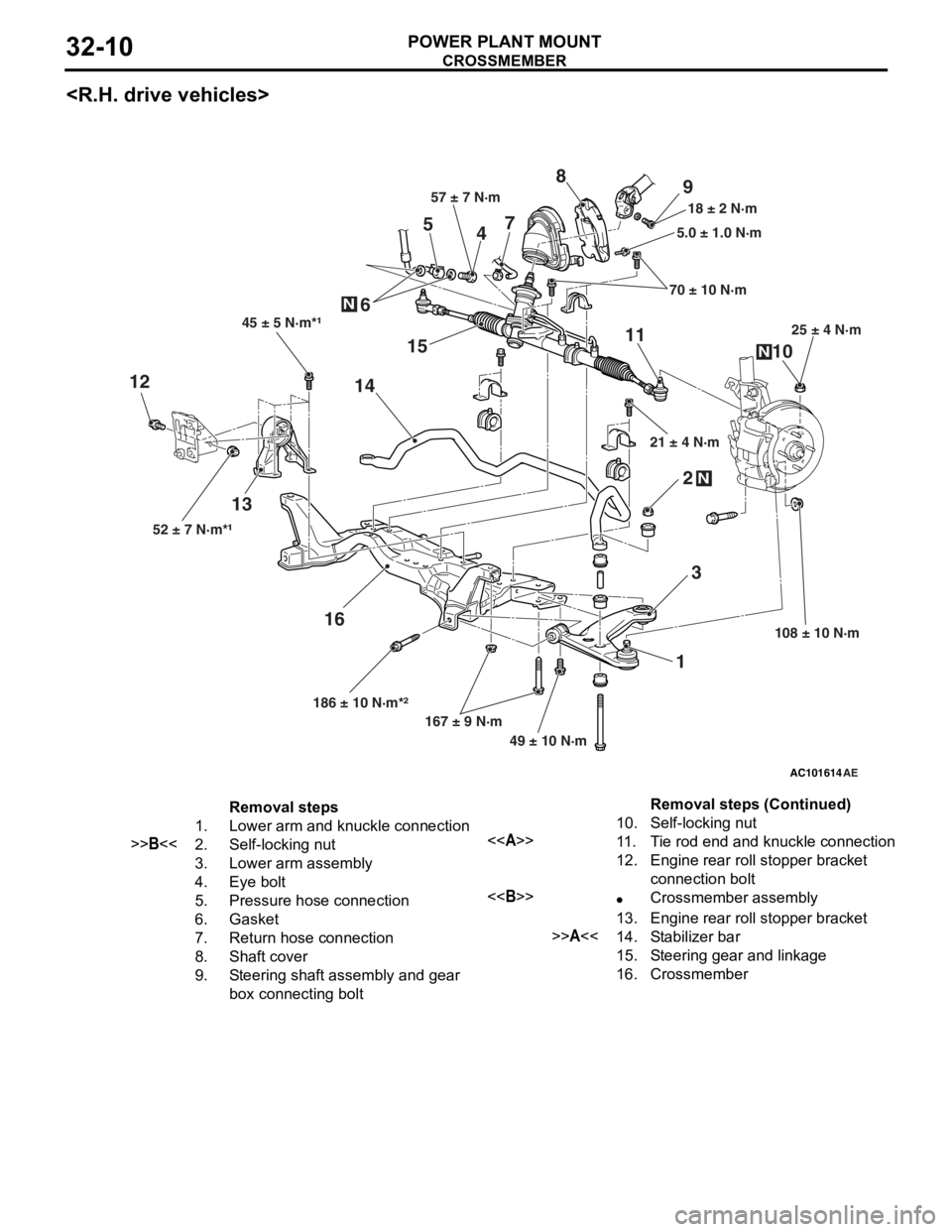
Removal steps
1.Lower arm and knuckle connection
>>B<<2.Self-locking nut
3.Lower arm assembly
4.Eye bolt
5.Pressure hose connection
6.Gasket
7.Return hose connection
8.Shaft cover
9.Steering shaft assembly and gear
box connecting bolt
10.Self-locking nut
<>11 .Tie rod end and knuckle connection
12.Engine rear roll stopper bracket
connection bolt
<>•Crossmember assembly
13.Engine rear roll stopper bracket
>>A<<14.Stabilizer bar
15.Steering gear and linkage
16.Crossmember
Removal steps (Continued)
Page 272 of 800
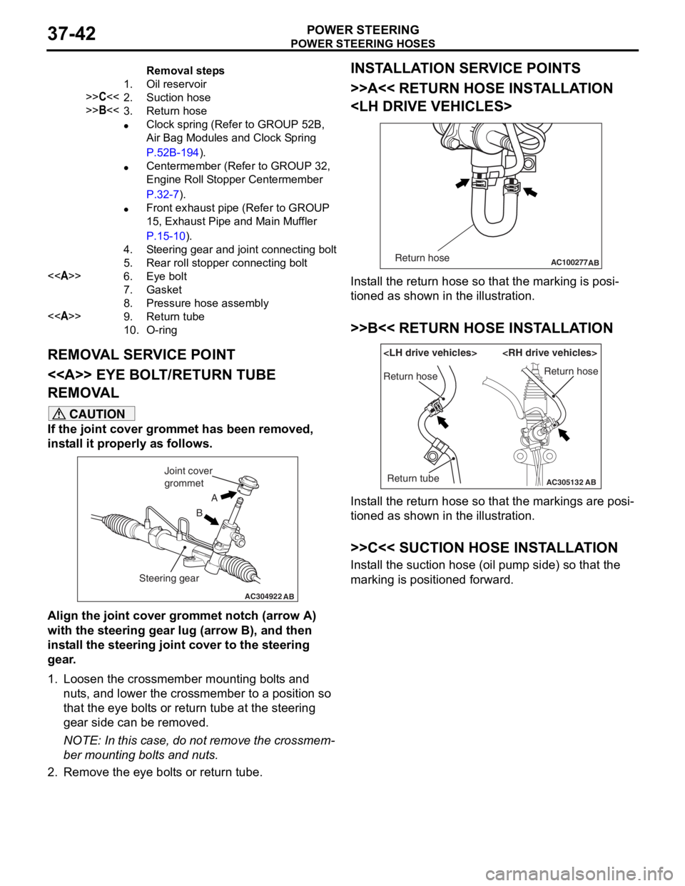
Removal steps
1.Oil reservoir
>>C<<2.Suction hose
>>B<<3.Return hose
•Clock spring (Refer to GROUP 52B,
Air Bag Modules and Clock Spring
P.52B-194).
•Centermember (Refer to GROUP 32,
Engine Roll Stopper Centermember
P.32-7).
•Front exhaust pipe (Refer to GROUP
15, Exhaust Pipe and Main Muffler
P.15-10).
4.Steering gear and joint connecting bolt
5.Rear roll stopper connecting bolt
<>6.Eye bolt
7.Gasket
8.Pressure hose assembly
<>9.Return tube
10.O-ring
POWE R STEERING HOSES
POWER S T E E RING37-42
REMOVA L SER V ICE POINT
<> EYE BOLT /RETURN TUBE
REMOV
A L
CAUTION
If the joint cover grommet has been removed,
install it properly as follows.
AC304922AB
A
B
Joint cover
grommet
Steering gear
Align the joint cover grommet notch (arrow A)
with the steering gear lug (arrow B), and then
install the steering joint cover to the steering
gear.
1. Loosen the crossmember mounting bolts and nuts, and lower the crossmember to a position so
that the eye bolts or return tube at the steering
gear side can be removed.
NOTE: In this case, do not remove the crossmem-
ber mounting bolts and nuts.
2. Remove the eye bolts or return tube.
INSTALLATION SERVICE POINTS
>>A<< RETURN HOSE INSTALLATION
AC100277 ABReturn hose
Install the return hose so that the marking is posi-
tioned as shown in the illustration.
>>B<< RETURN HOSE INSTALLATION
AC305132AB
Return hose
Return tubeReturn hose
Install the return hose so that the markings are posi-
tioned as shown in the illustration.
>>C<< SUCTION HOSE INSTALLATION
Install the suction hose (oil pump side) so that the
marking is positioned forward.
Page 292 of 800
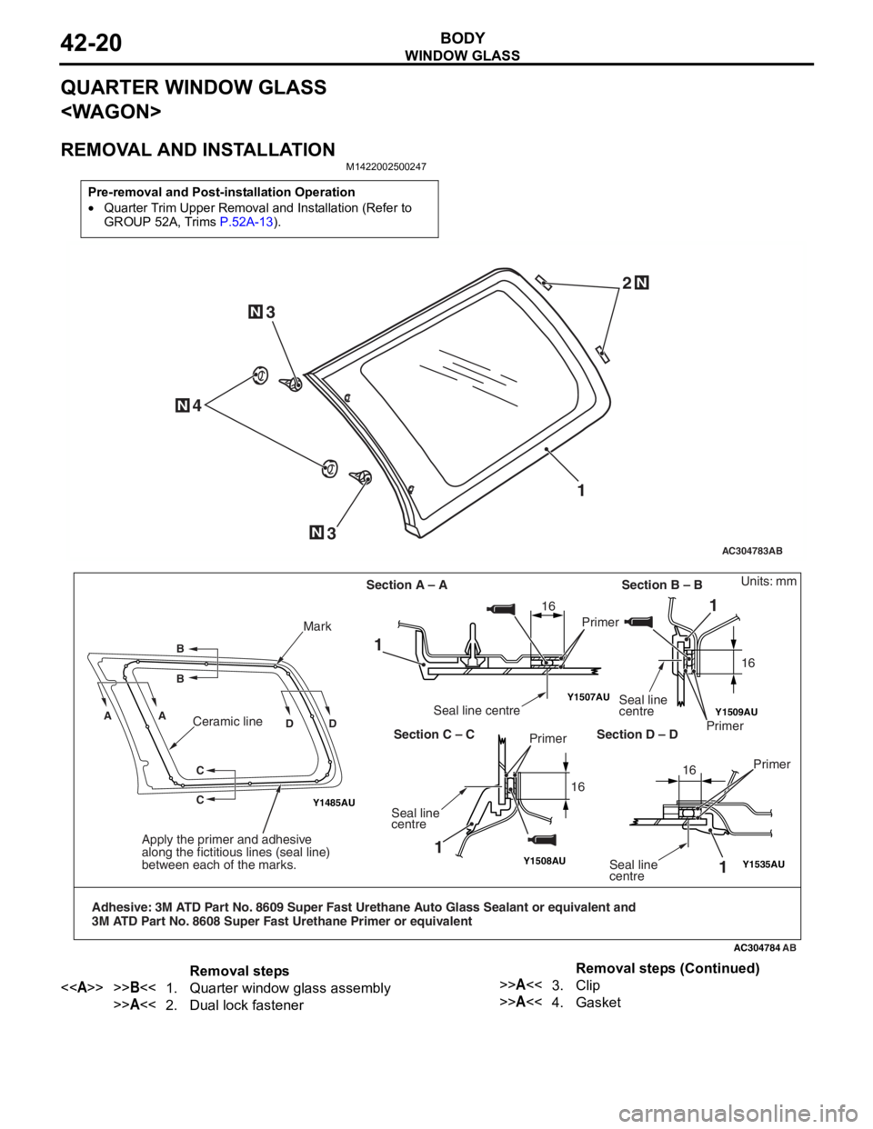
WINDOW GLASS
BODY42-20
QUARTER WINDOW GLASS
REMOVAL AND INSTALLATION
M1422002500247
Pre-removal and Post-installation Operation
•Quarter Trim Upper Removal and Installation (Refer to
GROUP 52A, Trims
P.52A-13).
AC304783
N
N
N
12
3
N3
4
AB
Y1509AU
Y1508AU
Y1507AU
Y1485AU
Y1535AU
AC304784
AA B B
DD
C
C
Mark
Apply the primer and adhesive
along the fictitious lines (seal line)
between each of the marks.
Adhesive: 3M ATD Part No. 8609 Super Fast Urethane Auto Glass Sealant or equivalent and
3M ATD Part No. 8608 Super Fast Urethane Primer or equivalent
1
1
1
Seal line centrePrimer
Section A – A Section B – BSeal line
centre
Primer
Section C – C Section D – D
Seal line
centre Primer
1Seal line
centre
Units: mm
Primer
16
16 1616
Ceramic line
AB
Removal steps
<>>>B<<1.Quarter window glass assembly
>>A<<2.Dual lock fastener
>>A<<3.Clip
>>A<<4.Gasket
Removal steps (Continued)
Page 294 of 800
WINDOW GLASS
BODY42-22
INSTALLATION SERVICE POINTS
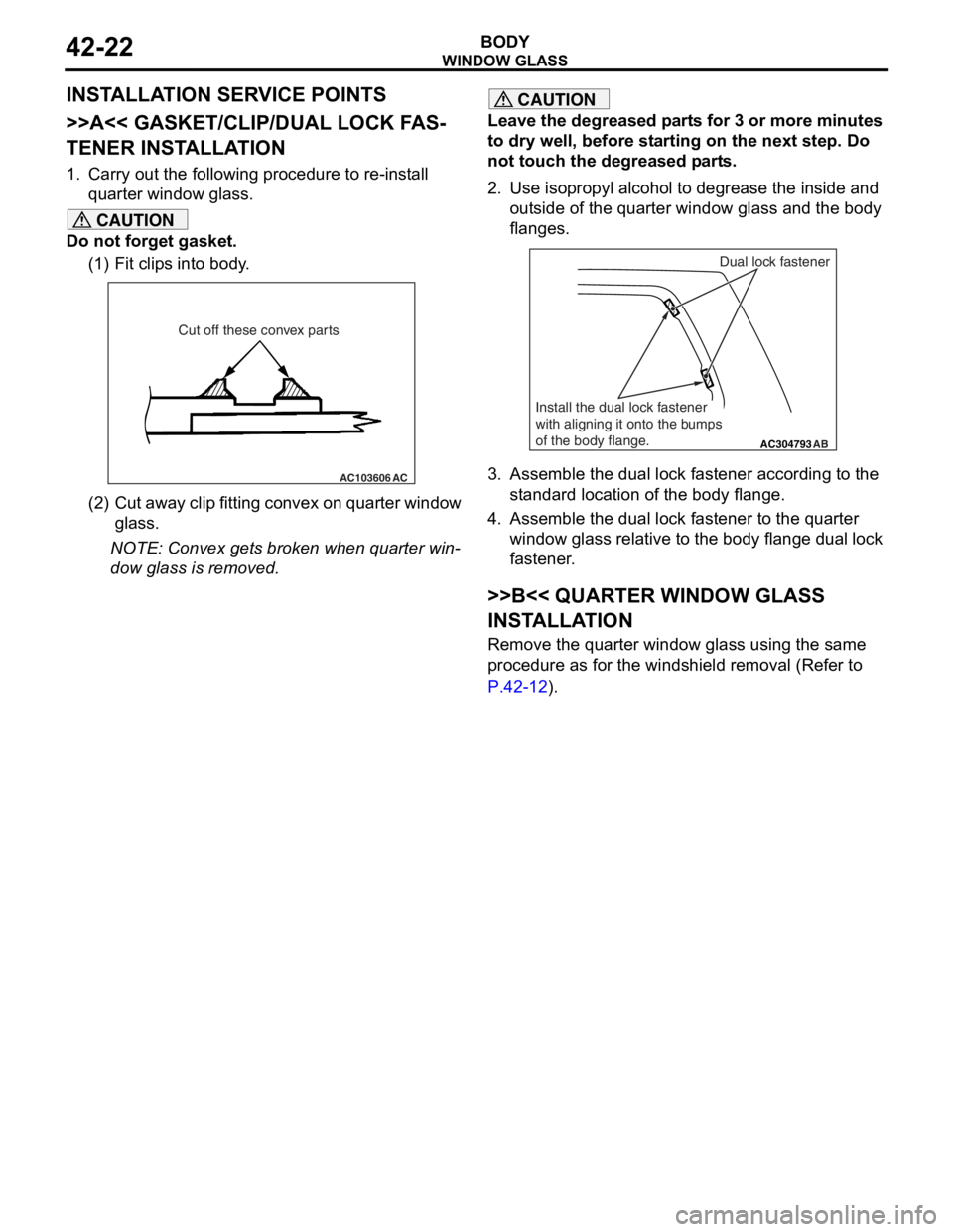
>>A<< GASKET/CLIP/DUAL LOCK FAS-
TENER INSTALLATION
1. Carry out the following procedure to re-install quarter window glass.
CAUTION
Do not forget gasket.
(1) Fit clips into body.
AC103606 AC
Cut off these convex parts
(2) Cut away clip fitting convex on quarter window
glass.
NOTE: Convex gets broken when quarter win-
dow glass is removed.
CAUTION
Leave the degreased parts for 3 or more minutes
to dry well, before starting on the next step. Do
not touch the degreased parts.
2. Use isopropyl alcohol to degrease the inside and
outside of the quarter window glass and the body
flanges.
AC304793AB
Dual lock fastener
Install the dual lock fastener
with aligning it onto the bumps
of the body flange.
3. Assemble the dual lock fastener according to the standard location of the body flange.
4. Assemble the dual lock fastener to the quarter window glass relative to the body flange dual lock
fastener.
>>B<< QUARTER WINDOW GLASS
INSTALLATION
Remove the quarter window glass using the same
procedure as for the windshield removal (Refer to
P.42-12).