ABS MITSUBISHI LANCER 2006 Owner's Guide
[x] Cancel search | Manufacturer: MITSUBISHI, Model Year: 2006, Model line: LANCER, Model: MITSUBISHI LANCER 2006Pages: 800, PDF Size: 45.03 MB
Page 250 of 800
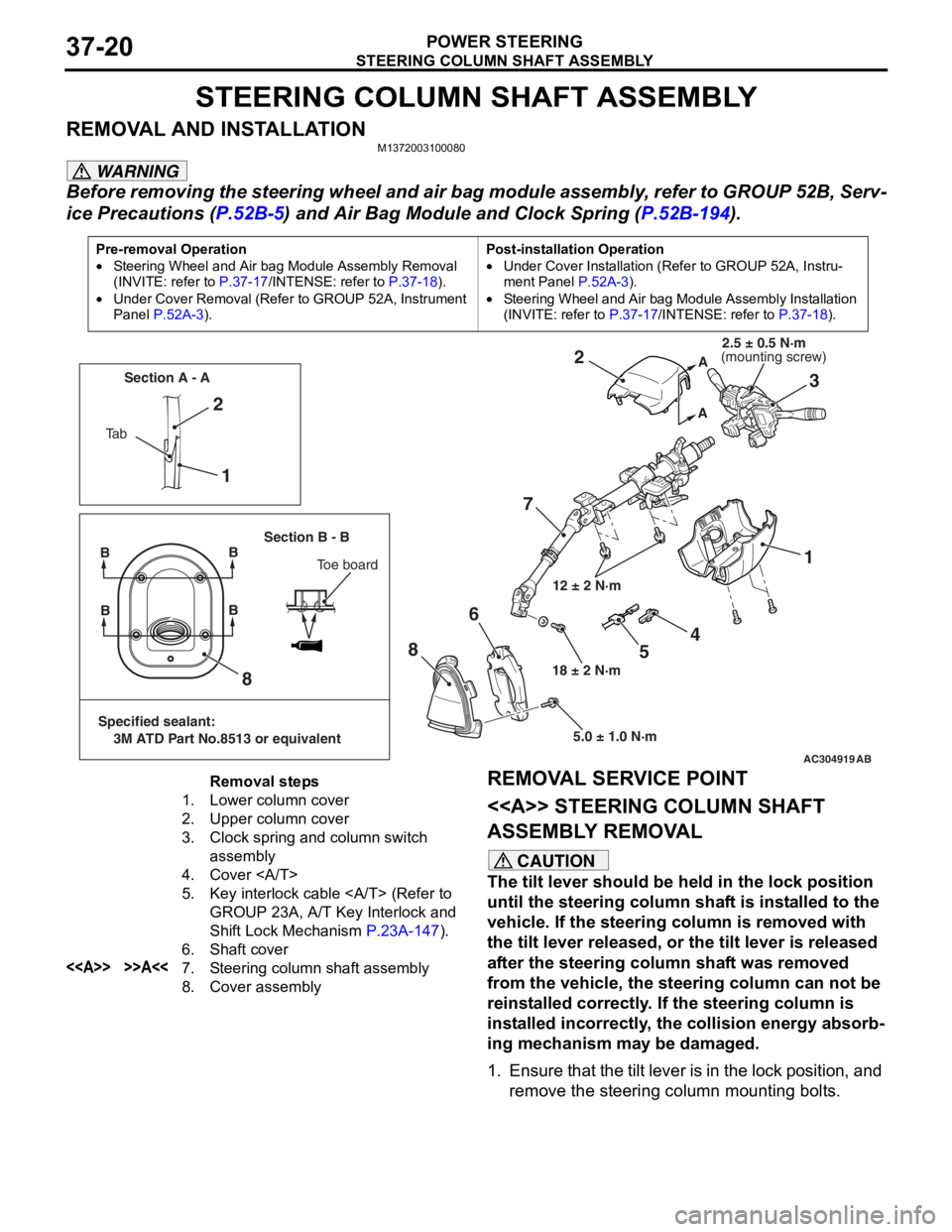
STEERING COLUMN SHAFT ASSEMBLY
POWER STEERING37-20
STEERING COLUMN SHAFT ASSEMBLY
REMOVAL AND INSTALLATIONM1372003100080
WARNING
Before removing the steering wheel and air bag module assembly, refer to GROUP 52B, Serv-
ice Precautions (P.52B-5) and Air Bag Module and Clock Spring (P.52B-194).
Pre-removal Operation
•Steering Wheel and Air bag Module Assembly Removal
(INVITE: refer to
P.37-17/INTENSE: refer to P.37-18).
•Under Cover Removal (Refer to GROUP 52A, Instrument
Panel
P.52A-3).
Post-installation Operation
•Under Cover Installation (Refer to GROUP 52A, Instru-
ment Panel P.52A-3).
•Steering Wheel and Air bag Module Assembly Installation
(INVITE: refer to
P.37-17/INTENSE: refer to P.37-18).
AC304919AB
12 ± 2 N·m
18 ± 2 N·m 5.0 ± 1.0 N·m
1
2
73
2
1
8
8 6
A
A
Ta b Section A - A
Section B - B
BB
Toe board
Specified sealant:
3M ATD Part No.8513 or equivalent
BB
4
5
(mounting screw)2.5 ± 0.5 N·m
Removal steps
1.Lower column cover
2.Upper column cover
3.Clock spring and column switch
assembly
4.Cover
5.Key interlock cable (Refer to
GROUP 23A, A/T Key Interlock and
Shift Lock Mechanism
P.23A-147).
6.Shaft cover
<>>>A<<7.Steering column shaft assembly
8.Cover assembly
REMOVAL SERVICE POINT
<> STEERING
COLUMN SHAFT
ASSEMBLY REMOVAL
CAUTION
The tilt lever should be held in the lock position
until the steering column shaft is installed to the
vehicle. If the steering column is removed with
the tilt lever released, or the tilt lever is released
after the steering column shaft was removed
from the vehicle, the steering column can not be
reinstalled correctly. If the steering column is
installed incorrectly, the collision energy absorb
-
ing mechanism may be damaged.
1. Ensure that the tilt lever is in the lock position, and remove the steering column mounting bolts.
Page 251 of 800
AC210969AD
Clip
Steering column
shaft
STE E RING C O LUMN SHAFT AS SEMBL Y
POWER STEERING37-21
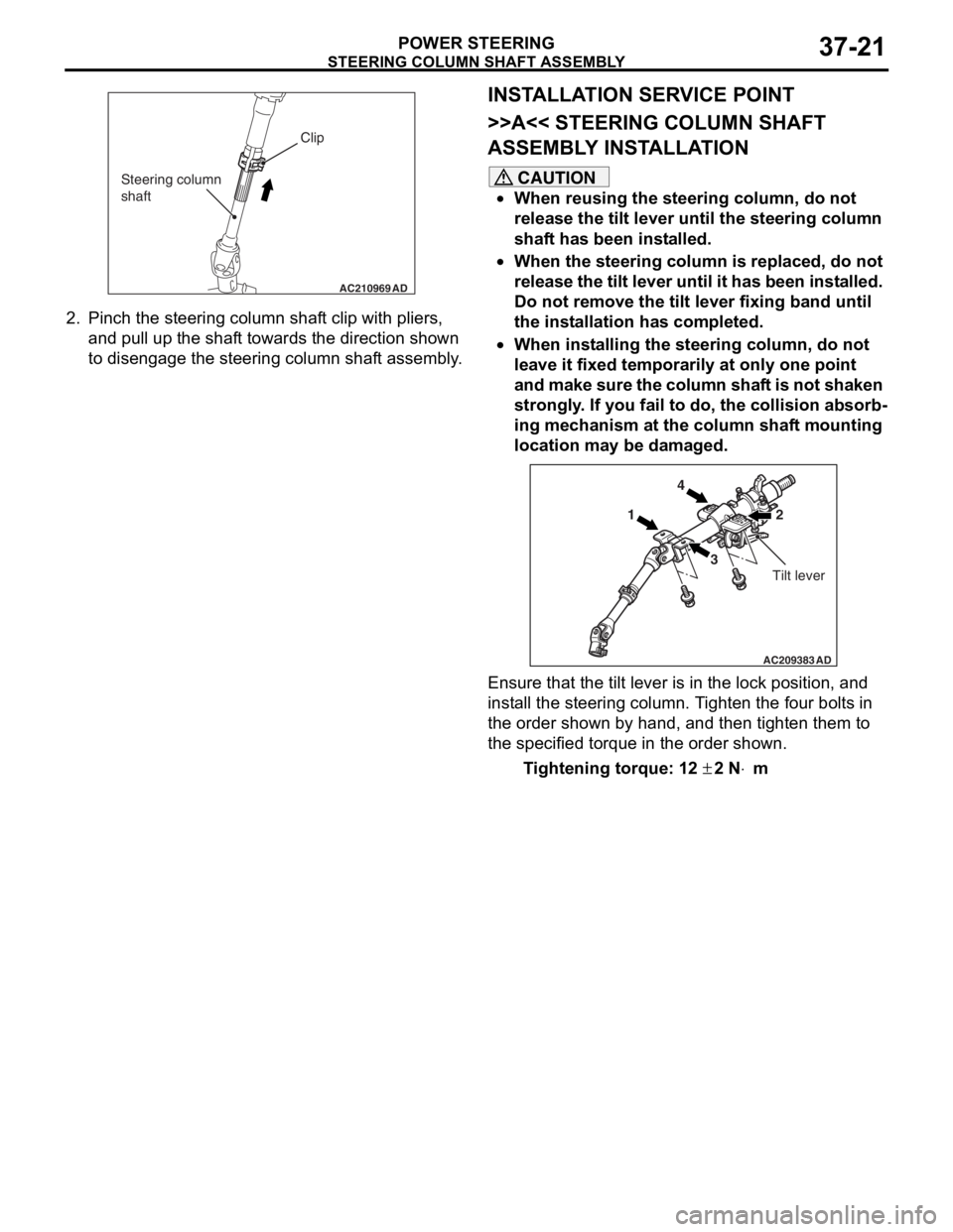
2.Pin c h t he st eering column shaf t clip with pliers,
an d pull up the shaf t towards the d i rection shown
to disengag e the steering column shaf t assembly .
INSTALLA T ION SER VICE POINT
>>A<< STEERING COLUMN SHAFT
ASSEMBL
Y INST ALLA TION
CAUTION
•When reusing the steering column, do not
release the tilt lever until the steering column
shaft has been installed.
•When the steering column is replaced, do not
release the tilt lever until it has been installed.
Do not remove the tilt lever fixing band until
the installation has completed.
•When installing the steering column, do not
leave it fixed temporarily at only one point
and make sure the column shaft is not shaken
strongly. If you fail to do, the collision absorb
-
ing mechanism at the column shaft mounting
location may be damaged.
AC209383AD
14
3 2
Tilt lever
Ensure that the tilt lever is in the lock position, and
install the steering column. Tighten the four bolts in
the order shown by hand, and then tighten them to
the specified torque in the order shown.
Tightening torque: 12 ± 2 N⋅m
Page 288 of 800
ACX00480
10 mm15 mm
AB
WI ND OW GLAS S
BODY42-16
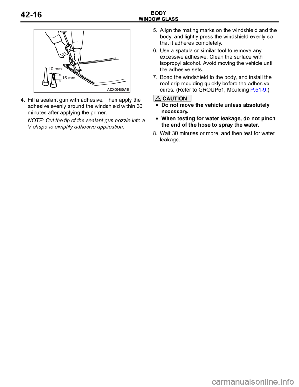
4.Fill a sea l ant gun with adhe sive. The n apply th e
ad hesive even ly a r ound the wind shield within 3 0
minut es af ter applying the pr ime r .
NOTE: Cut the tip of t he seala n t gu n nozzle into a
V shape to simplify adhesive app licatio n.
5.Align t he mating ma rks on th e windshie l d a nd the
b ody , and lig htly press the windshield evenly so
th at it adheres co mpletely .
6.Use a sp a t ula o r similar tool to re move any
e xce ssive adhesive. Clean the surface with
isopr opyl alcohol. A v o i d moving the veh i cle unt il
th e adhe sive set s .
7.Bon d the windsh i eld to the body , a nd in st all the
ro of drip mou l din g quickly b e fore t he adh esive
cures. (Refer to GROUP51, Mou l din g
P.51-9.)
CAUTION
•Do not move the vehicle unless absolutely
necessary.
•When testing for water leakage, do not pinch
the end of the hose to spray the water.
8. Wait 30 minutes or more, and then test for water leakage.
Page 392 of 800
ECU
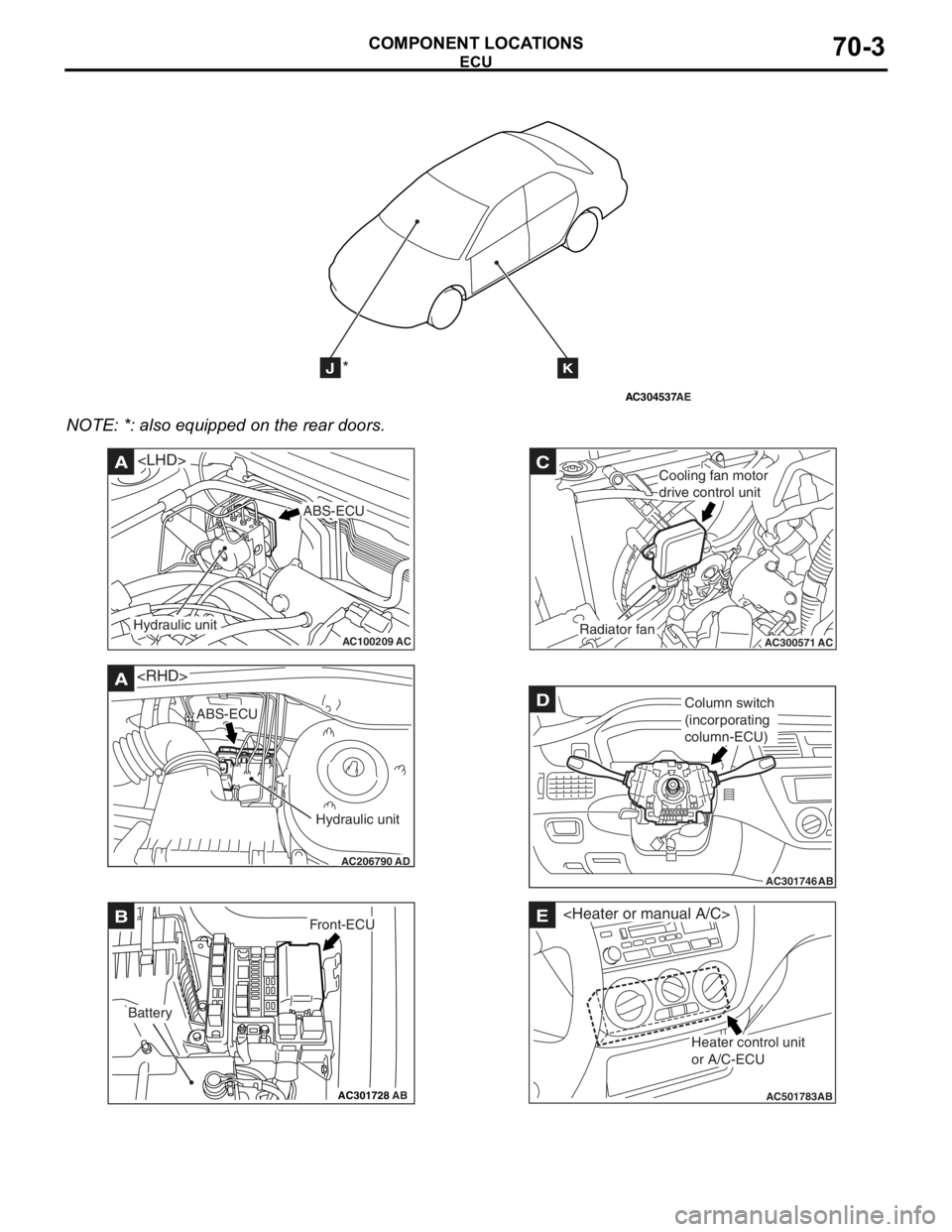
COMPONENT LOCATIONS70-2
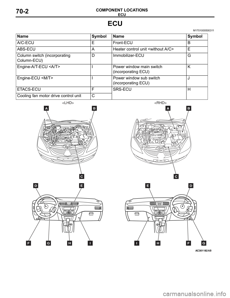
ECU
M1701000500311
NameSymbolNameSymbol
A/C-ECUEFront-ECUB
ABS-ECUAHeater control unit
Column switch (incorporating
Column-ECU)DImmobilizer-ECUG
Engine-A/T-ECU IPower window main switch
(incorporating ECU)K
Engine-ECU
(incorporating ECU)J
ETACS-ECUFSRS-ECUH
Cooling fan motor drive control unitC
AC301182
DE
AB
C
FGHI
AB
DE
AB
C
FGHI
Page 393 of 800
AC304537
JK*
AE
ECU
COMPONENT LOCA TIONS70-3
NOTE: *: also eq uipp ed on the rear doors.
AC100209AC
A
ABS-ECU
Hydraulic unit
AC206790
A
AD
ABS-ECU
Hydraulic unit
AC301728AB
BFront-ECU
Battery
AC300571
C
ACRadiator fan
Cooling fan motor
drive control unit
AC301746
DColumn switch
(incorporating
column-ECU)
AB
AC501783AB
E
Heater control unit
or A/C-ECU
Page 396 of 800
SENSOR
COMPONENT LOCATIONS70-6
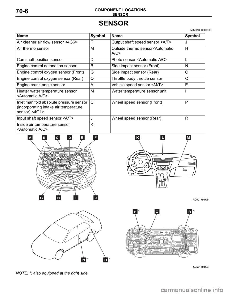
SENSOR
M1701000600909
NameSymbolNameSymbol
Air cleaner air flow sensor <4G6>FOutput shaft speed sensor J
Air thermo sensorMOutside thermo sensor
Camshaft position sensorDPhoto sensor
Engine control detonation sensorBSide impact sensor (Front)N
Engine control oxygen sensor (Front)GSide impact sensor (Rear)O
Engine control oxygen sensor (Rear)QThrottle body throttle sensorC
Engine crank angle sensorAVehicle speed sensor
Heater water temperature sensor
Inlet manifold absolute pressure sensor
(incorporating intake air temperature
sensor) <4G1>CWheel speed sensor (Front)P
Input shaft speed sensor JWheel speed sensor (Rear)R
Inside air temperature sensor
AC501790
BDCFEA
GHIJ
MKL
AB
AC501791AB
NO
POR
** *
*
NO
TE: *: also eq uipp ed at t he rig h t side.
Page 397 of 800
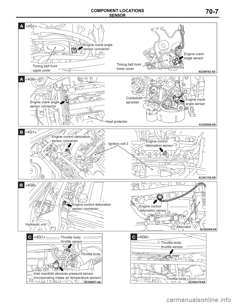
AC208762
A
AD
Timing belt front
upper coverTiming belt front
lower coverEngine crank
angle sensor
<4G1>
Engine crank angle
sensor connector
AC302008
A<4G6>
ABHeat protector
Crankshaft
sprocket
Engine crank angle
sensor connectorEngine crank
angle sensor
AC301752
B
AB
Ignition coil 2
<4G1>
Engine control detonation
sensor connector
Engine control
detonation sensor
AC302009
B
AB
Hydraulic unit
<4G6>
Alternator
Engine control detonation
sensor connectorEngine control
detonation sensor
AC208541
C
AE
<4G1>
Throttle body
Throttle body
throttle sensor
Inlet manifold absolute pressure sensor
(incorporating intake air temperature sensor)
AC302479
AB
C
Throttle body
<4G6>
Throttle body
throttle sensor
SENSOR
COMPONENT LOCA TIONS70-7
Page 422 of 800

ENGINE AND TRANSMISSION
CONFIGURATION DIAGRAMS80-12
ENGINE AND TRANSMISSION <4G1-MPI (LHD)> (CONTINUED)
AC301129AE
B-118B-101 B-102
B-113
B-114
B-115
B-116 B-117
Earth cable
Control wiring
harness
Connector colour
code
B : Black
BR : Brown
G : Green
GR : Grey
L : Blue
None : Milk white
O : Orange
R : Red
V : Violet
Y : Yellow
Connector
symbol
-101
thru
-118
B
*
B-101(2-BR)Emission solenoid valve (EGR system)
B-102(4-GR)Inlet manifold absolu te pressure sensor
B-103(6-B)Throttle body idle speed control servo
B-104(3-GR)Ignition coil 1
B-105(2-B)Emission solenoid va lve (Purge control
system)
B-107(3-B)Camshaft position sensor
B-108(3-GR)Output shaft speed sensor
B-109(3-B)Input shaft speed sensor
B-110(2-B)Back-up lamp switch
B-111(2-B)Water temperature sensor unit
Page 423 of 800
AC301130AC
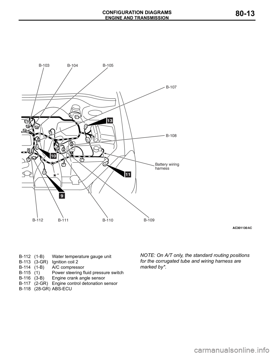
9
10
11
13
B-103B-104 B-105
B-107
B-108
Battery wiring
harness
B-109
B-110
B-111
*
B-112
B-112(1-B)Water temperature gauge unit
B-113(3-GR)Ignition coil 2
B-114(1-B)A/C compressor
B-115(1)Power steering fluid pressure switch
B-116(3-B)Engine crank angle sensor
B-117(2-GR)Engine control detonation sensor
B-118(28-GR)ABS-ECU
ENGINE AND TRA
N SMISSION
CONF IGURA TION D I A G RA MS80-13
NOTE: On A/T only , the st andard routing positions
for the
corrug a ted tu be and wiring harne ss are
marked by*.
Page 426 of 800
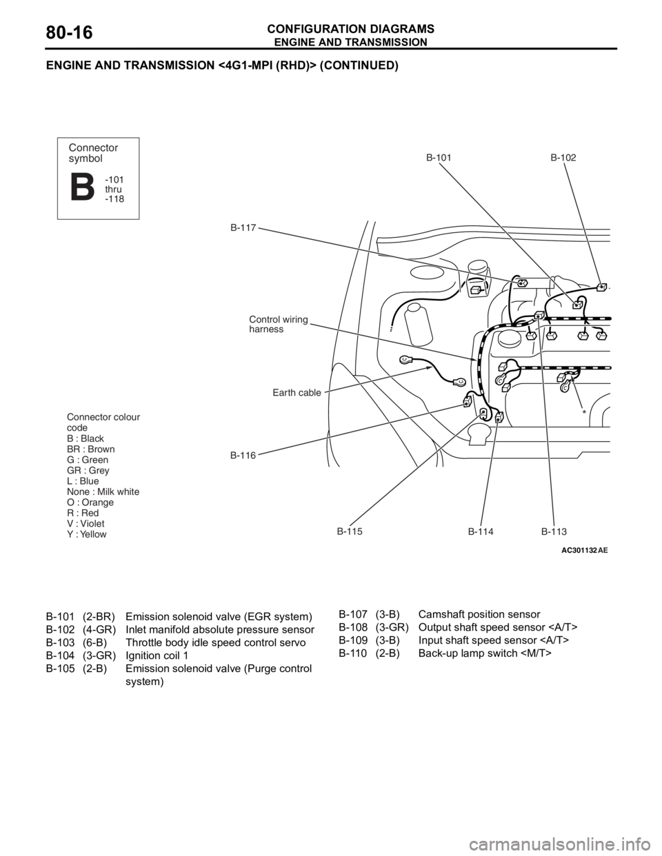
ENGINE AND TRANSMISSION
CONFIGURATION DIAGRAMS80-16
ENGINE AND TRANSMISSION <4G1-MPI (RHD)> (CONTINUED)
AC301132AE
B-117B-101 B-102
B-113
B-114
B-115
B-116
Earth cable
Control wiring
harness
Connector colour
code
B : Black
BR : Brown
G : Green
GR : Grey
L : Blue
None : Milk white
O : Orange
R : Red
V : Violet
Y : Yellow
Connector
symbol
-101
thru
-118
B
*
B-101(2-BR)Emission solenoid valve (EGR system)
B-102(4-GR)Inlet manifold absolu te pressure sensor
B-103(6-B)Throttle body idle speed control servo
B-104(3-GR)Ignition coil 1
B-105(2-B)Emission solenoid va lve (Purge control
system)
B-107(3-B)Camshaft position sensor
B-108(3-GR)Output shaft speed sensor
B-109(3-B)Input shaft speed sensor
B-110(2-B)Back-up lamp switch