ECU MITSUBISHI LANCER 2006 Owner's Guide
[x] Cancel search | Manufacturer: MITSUBISHI, Model Year: 2006, Model line: LANCER, Model: MITSUBISHI LANCER 2006Pages: 800, PDF Size: 45.03 MB
Page 162 of 800
REAR AXLE HUB ASSEMBLY
REAR AXLE27-6
<
AC210936AC
MD998815
MD998801 MD998813
MD998812
Rear hub assembly
ABS rotor
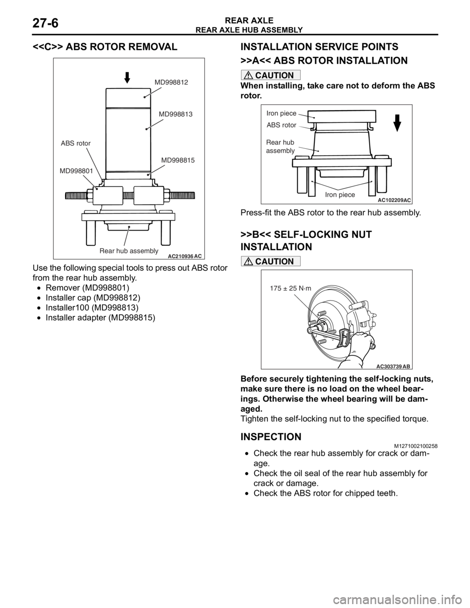
Use
the fo llowing specia l to ols t o press o u t ABS rot o r
from th
e rear h ub assembly .
•Remover (MD99880 1)
•Insta lle r cap (MD9988 12)
•Insta lle r100 (MD9 98813 )
•Insta lle r adapte r (MD998 815)
INSTALLA T ION SER VICE POINTS
>>A<< ABS ROTO R INST ALLA TION
CAUTION
When installing, take care not to deform the ABS
rotor.
AC102209
Iron piece
ABS rotor
Rear hub
assembly
Iron piece
AC
Press-fit the ABS rotor to the rear hub assembly.
>>B<< SELF-LOCKING NUT
INSTALLATION
AC303739
175 ± 25 N·m
AB
CAUTION
Before securely tightening the self-locking nuts,
make sure there is no load on the wheel bear
-
ings. Otherwise the wheel bearing will be dam-
aged.
Tighten the self-locking nut to the specified torque.
INSPECTIONM1271002100258
•Check the rear hub assembly for crack or dam-
age.
•Check the oil seal of the rear hub assembly for
crack or damage.
•Check the ABS rotor for chipped teeth.
Page 174 of 800
ENGINE MOUNTING
POWER PLANT MOUNT32-4
ENGINE MOUNTING
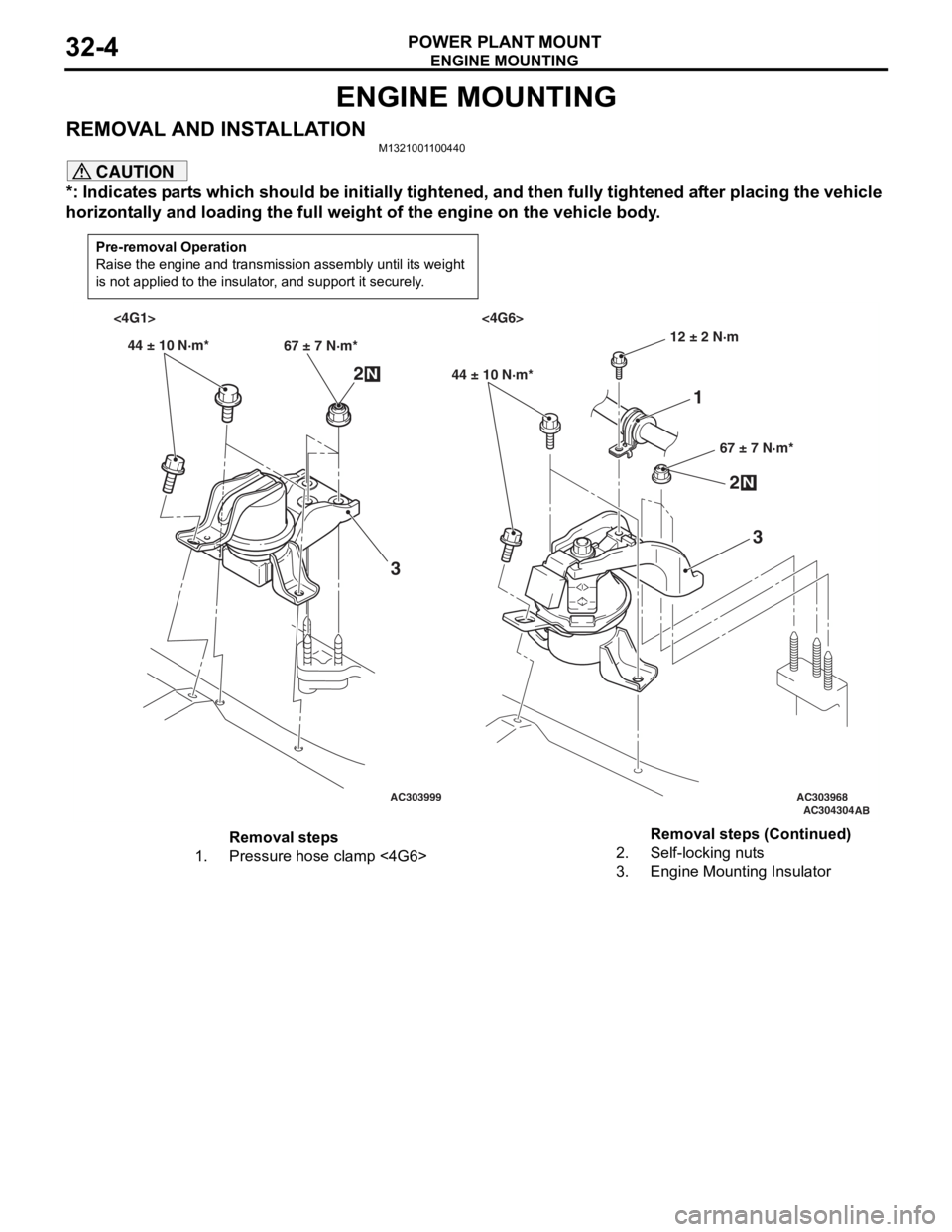
REMOVAL AND INSTALLATIONM1321001100440
CAUTION
*: Indicates parts which should be initially tightened, and then fully tightened after placing the vehicle
horizontally and loading the full weight of the engine on the vehicle body.
Pre-removal Operation
Raise the engine and transmission assembly until its weight
is not applied to the insulator, and support it securely.
AC303999AC303968AC304304AB
<4G1> <4G6>
44 ± 10 N·m* 67 ± 7 N·m*
2N
3
44 ± 10 N·m*
67 ± 7 N·m*
2N
3
12 ± 2 N·m
1
Removal steps
1.Pressure hose clamp <4G6>2.Self-locking nuts
3.Engine Mounting Insulator
Removal steps (Continued)
Page 175 of 800
TRANSMISSION MOUNTING
POWER PLANT MOUNT32-5
TRANSMISSION MOUNTING
REMOVAL AND INSTALLATIONM1321001400430
CAUTION
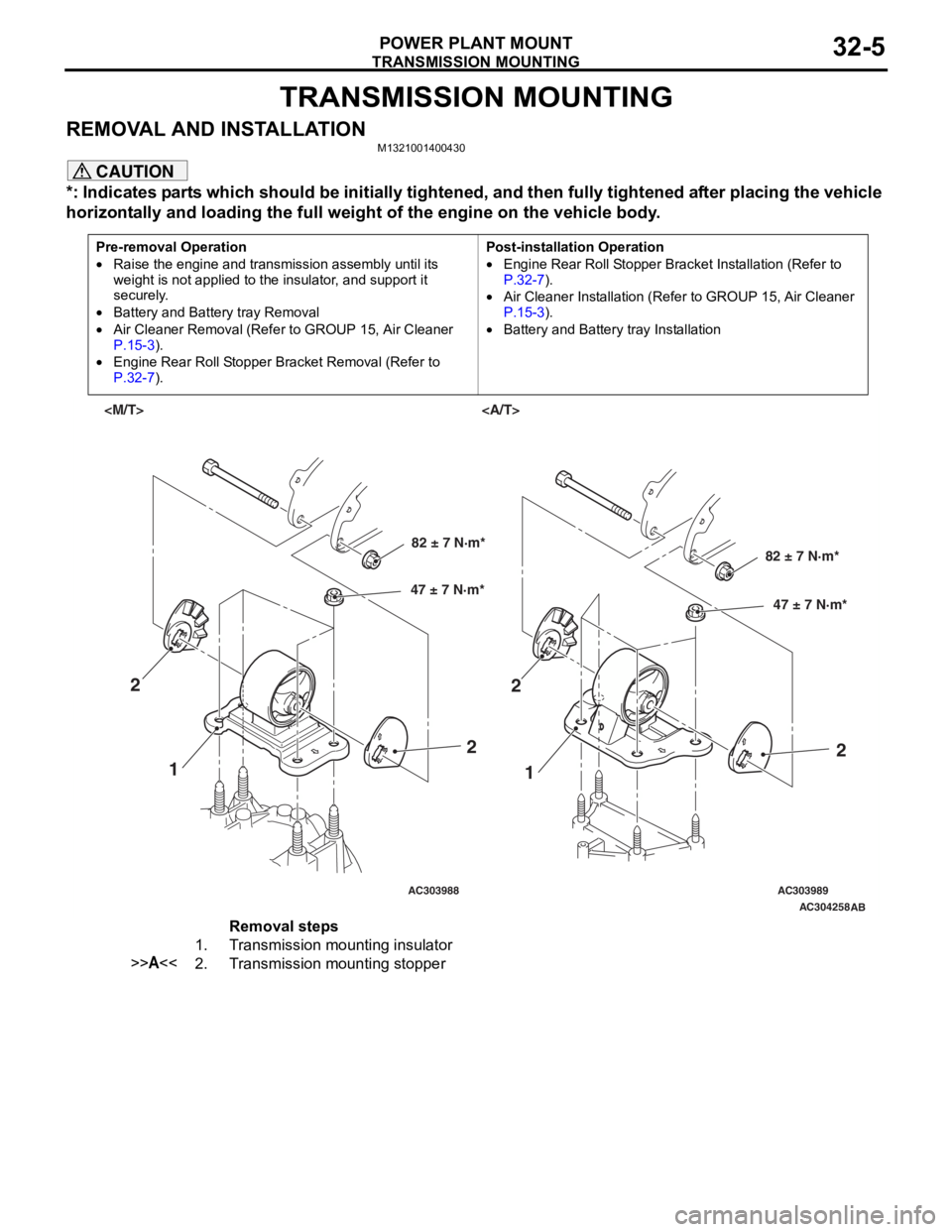
*: Indicates parts which should be initially tightened, and then fully tightened after placing the vehicle
horizontally and loading the full weight of the engine on the vehicle body.
Pre-removal Operation
•Raise the engine and transmission assembly until its
weight is not applied to the insulator, and support it
securely.
•Battery and Battery tray Removal
•Air Cleaner Removal (Refer to GROUP 15, Air Cleaner
P.15-3).
•Engine Rear Roll Stopper Bracket Removal (Refer to
P.32-7).
Post-installation Operation
•Engine Rear Roll Stopper Bracket Installation (Refer to
P.32-7).
•Air Cleaner Installation (Refer to GROUP 15, Air Cleaner
P.15-3).
•Battery and Battery tray Installation
AC303988AC303989AC304258
AB
82 ± 7 N·m*
47 ± 7 N·m*82 ± 7 N·m*
47 ± 7 N·m*
1 1
2
22
2
Removal steps
1.Transmission mounting insulator
>>A<<2.Transmission mounting stopper
Page 191 of 800
Page 214 of 800
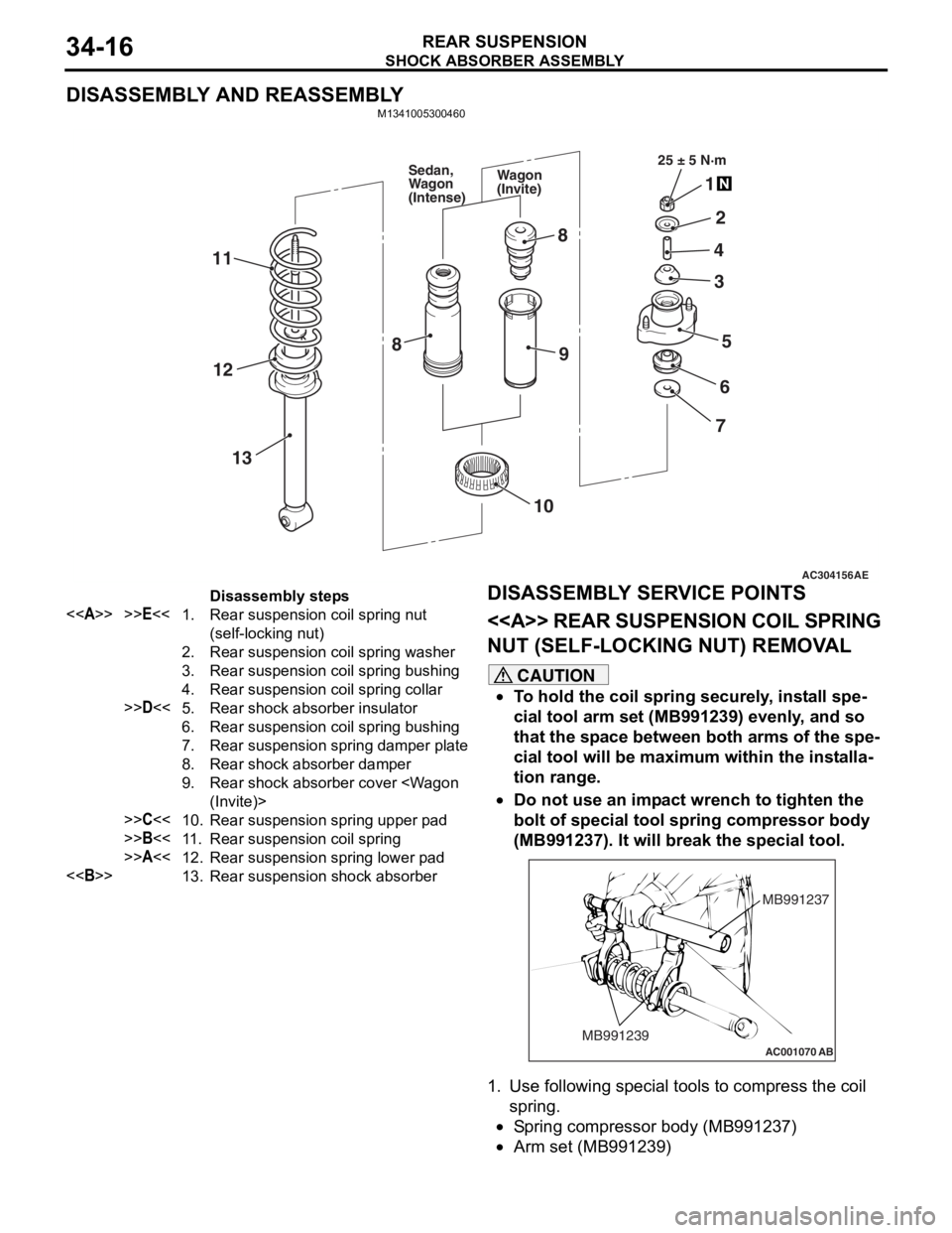
SHOCK ABSORBER ASSEMBLY
REAR SUSPENSION34-16
DISASSEMBLY AND REASSEMBLY
M1341005300460
AC304156AE
25 ± 5 N·m
1
2
4
5
3
6
7
8
9
11
13
12
10
8
Wagon
(Invite)
Sedan,
Wagon
(Intense)
Disassembly steps
<>>>E<<1.Rear suspension coil spring nut
(self-locking nut)
2.Rear suspension coil spring washer
3.Rear suspension coil spring bushing
4.Rear suspension coil spring collar
>>D<<5.Rear shock absorber insulator
6.Rear suspension coil spring bushing
7.Rear suspension spring damper plate
8.Rear shock absorber damper
9.Rear shock absorber cover
>>C<<10.Rear suspension spring upper pad
>>B<<11 .Rear suspension coil spring
>>A<<12.Rear suspension spring lower pad
<>13.Rear suspension shock absorber
DISASSEMBL
Y SER V ICE POINTS
<> REAR SUSPENSION COIL SPRING
NUT (SELF-LOCKING NUT) REMOV
A L
CAUTION
•To hold the coil spring securely, install spe-
cial tool arm set (MB991239) evenly, and so
that the space between both arms of the spe
-
cial tool will be maximum within the installa-
tion range.
•
AC001070
MB991237
MB991239
AB
Do not use an impact wrench to tighten the
bolt of special tool spring compressor body
(MB991237). It will break the special tool.
1. Use following special tools to compress the coil spring.
•Spring compressor body (MB991237)
•Arm set (MB991239)
Page 218 of 800
STABILIZER BAR
REAR SUSPENSION34-20
STABILIZER LINK BALL JOINT TURNING
TORQUE CHECK
AC001129
MB990326
AB
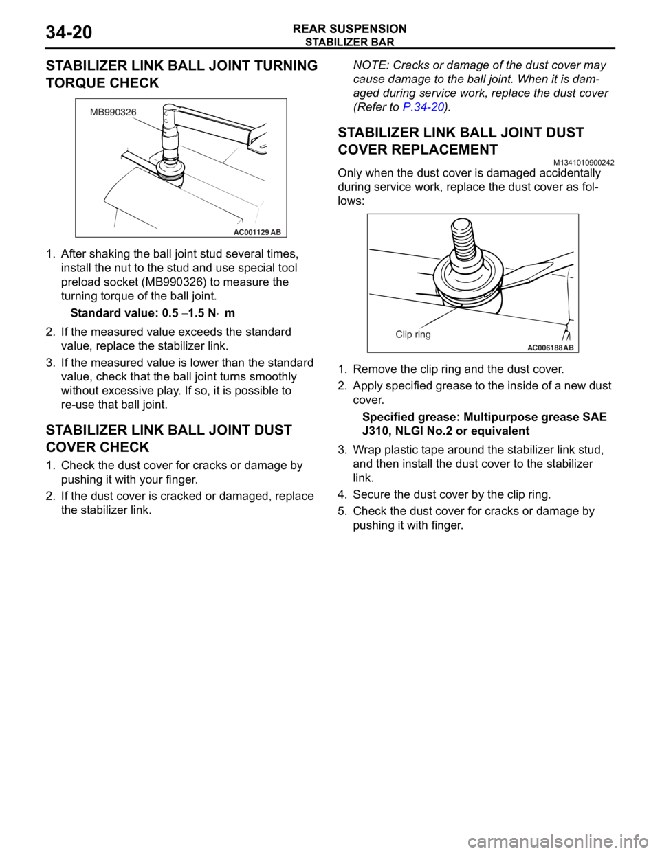
1.Af ter shaking th e ball jo int stud seve ral times,
inst all the n u t to t he st ud and use special tool
pre l oad socket (MB990 326) to measure th e
tu rning torque of the ball joint.
St andard va lue: 0.5 − 1.5 N⋅m
2.If the measu r ed value exceeds the st a ndard
value , replace the st ab ilizer link.
3.If the measu r ed value is lower tha n the st andard
value , che c k that th e ball jo int tu rns smoo thly
wit hout exce ssive play . I f so, it is possible to
re- u se t hat ball joint.
STABILIZER LINK BALL JOINT DUST
COVER CHECK
1. Check t he dust co ver fo r cracks or da mage by
pu shing it with your finger .
2.If the du st cover is cracked o r damaged, replace
th e st abilizer link.
NOTE: Cracks or dama ge of t he dust co ver may
cause damage to the b a ll join t. When it is dam
-
aged du ring service wo rk, rep l ace the d u st cover
(Refe
r to
P.34-2 0).
STABILIZER LINK BALL JOINT DUST
COVER REPLACEM
ENT
M13410109 0024 2
Only when the du st cover is d a ma ged accident ally
during
service work, repla c e th e dust cover as fol
-
lows:
AC006188 AB
Clip ring
1.Remove the clip ring and the dust cover .
2.App l y specified g r ease to t he insid e of a ne w dust
cov e r .
Specified grease: Multipurpos e grease SAE
J310,
NLGI No.2 o r e quivale n t
3.W r ap plast i c t ape aroun d the st a b ilize r lin k stud,
a nd then inst a ll th e dust co ver to the st a b ilizer
li nk.
4.Secure th e dust co ver by the clip rin g .
5.Check t he dust co ver f o r cracks or da mage by
p u shing it with finger .
Page 223 of 800
LUBRICANTS
PARKING BRAKES36-3
LUBRICANTS
M1361000400293
ItemSpecified lubricant
Rear brake shoe and backing plate contact surfaceBrake grease SAE J310, NLGI No.1
Rear brake shoe assembly
Rear brake shoe slack adjuster
ON-VEHIC LE SER VI CE
PARKING BRAKE LE VER STROKE
CHECK AND ADJUSTMENT
M13610009 0033 9
1.Pull the p a rkin g brake le ver wit h a force of
ap proxima t ely 200 N an d co unt the number of
no tche s.
St andard va lue: 5 − 7 notches
2.If the p a rking b r ake leve r stro ke is no t the
st a ndard valu e, adjust as de scribed below .
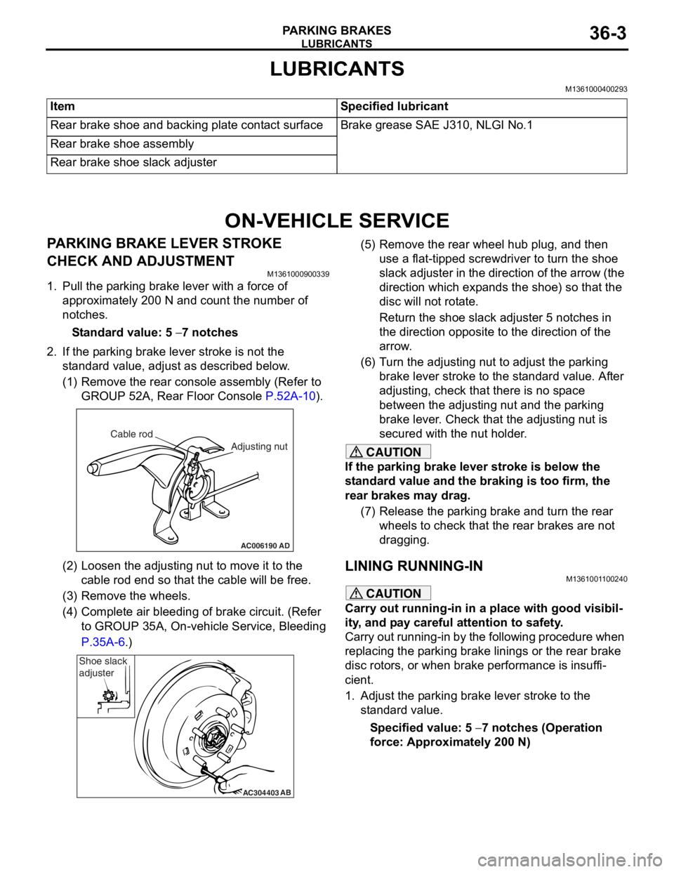
(1)R emove the rear console a sse mbly (Refer to
GROUP 5 2 A, Rear Floor Console
P.52A-10).
AC006190
Cable rod
Adjusting nut
AD
(2)Loosen th e adjusting nu t to move it to th e
cab l e rod end so tha t the cable will be fre e .
(3)R emove the wheels.
(4)C omplete a i r bleedin g of b r ake circuit. (Re f er
to GROUP 35A, On-ve h icle Service, Blee ding
P.35A-6.)
AC304403AB
Shoe slack
adjuster
(5
) R emove the rear whee l hub plug , and then
use a flat-tipped screwdriver to turn the shoe
slack ad juster in the direction of the arrow (the
dire ctio n which exp a nds the shoe) so that the
disc will no t rot a te.
Return the sh oe slack adjust e r 5 not ches in
the d
i rection opposite t o the d i rection of the
arrow
.
(6) T urn th e adjusting nut to adjust the p a rking
brake le ver stroke to the st anda rd value. Af ter
adjusting, check that there is n o sp ace
between the a d justing nut an d the p a rking
brake le ver . Che ck that th e adjusting nut is
secured with the nut ho lder .
CAUTION
If the parking brake lever stroke is below the
standard value and the braking is too firm, the
rear brakes may drag.
(7) Release the parking brake and turn the rear wheels to check that t he rear brakes are not
dragging.
LINING RUNNING-INM1361001100240
CAUTION
Carry out running-in in a place with good visibil-
ity, and pay careful attention to safety.
Carry out running-in by the following procedure when
replacing the parking brake linings or the rear brake
disc rotors, or when brake performance is insuffi
-
cient.
1. Adjust the parking brake lever stroke to the standard value.
Specified value: 5 − 7 notches (Operation
force: Approximately 200 N)
Page 243 of 800
ON-VEHICLE SERVICE
POWER STEERING37-13
STEERING WHEEL RETURN TO CENTRE
CHECK
M1372001800317
Conduct a road test:
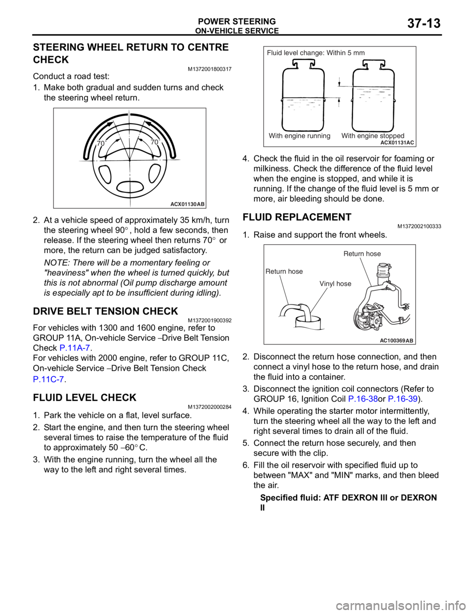
1. Make both gradual and sudden turns and check the steering wheel return.
ACX01130 AB
70˚ 70˚
2.
At a vehicle sp eed of a pproxima t ely 35 km/h, turn
th e ste e ring wh eel 9 0
°, ho ld a few se cond s, the n
release. If th
e ste
e
ring
wh eel t hen ret u rns 7 0
° or
more, th
e return
can
be ju
dged satisfactory
.
NOTE: There will be a mome nt a r y fee lin g or
"he
a
viness" when t he wheel is turned quickly , but
th
is is n o t abno rmal (Oil pu mp discharge amou nt
is especially a p t to b e insufficie n t during id lin g).
DRIVE BELT TENSION CHECK
M13720019 0039 2
For vehicles with 13 00 and 1600 engin e , refer to
GROUP 1
1 A, On-vehicle Service
− Drive Belt T ension
Che
c
k
P.11A-7.
For veh i cles wit h 2000 e ngin e , refer to GROUP 1 1 C,
On-vehicle Se
rvice
− Drive Belt Te nsion Check
P.1 1 C - 7.
FLUID LEVEL CHECK
M13720020 0028 4
1.Park the vehicle on a f l at, leve l su rface .
2.S t art the engine, and t hen tu rn the ste e ring wheel
seve ral times to raise the temperat ure of th e flu i d
to approximately 50
− 60°C.
3.With the engine run n ing, turn the wheel all the
way to the lef t an d righ t several times.
ACX01131With engine running With engine stoppedAC
Fluid level change: Within 5 mm
4.Check t he flu i d in the oil r e servoir f o r foaming or
milkine s s. Check the d i f f e r ence of the fluid le vel
when the e ngine is stop ped, an d while it is
ru nning . If the chan ge of th e fluid le vel is 5 mm or
more, a i r bleedin g sh ould be don e.
FLUID REPLACEMENT
M13720021 0033 3
1.Raise a nd su pport t he fron t wheels.
AC100369AB
Return hoseReturn hose
Vinyl hose
2. Disco nnect the re turn hose connection , and then
conne ct a vinyl hose to the re turn h o se, and drain
th e flu i d into a cont ain e r .
3.Disco nnect the ignition coil con necto rs (Refe r to
GROUP 16, Ignition Coil
P.16-38or P.16-39).
4.Wh ile operat ing th e st arter moto r inter m itt ently ,
tu rn the steering whee l all the wa y to t he le f t a nd
right seve ral times to dra i n all of the fluid.
5.Conn ect the retu rn hose se curely , and then
secu re with t he clip.
6.Fill the oil reservo i r with specified fluid u p to
b e tween "MAX" and "MIN" marks, and then bleed
th e air .
Specified fluid: A TF DEXRON III or DEXRON
II
Page 254 of 800
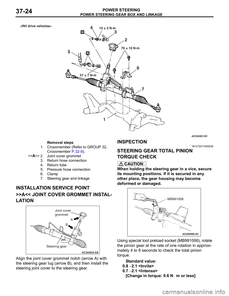
AC304921AC
57 ± 7 N·m 15 ± 3 N·m
70 ± 10 N·m
3
5 2
4
1
67
Removal steps
1.Crossmember (Refer to GROUP 32,
Crossmember
P.32-8).
>>A<<2.Joint cover grommet
3.Return hose connection
4.Return tube
5.Pressure hose connection
6.Clamp
7.Steering gear and linkage
PO WE R STEER ING GEAR BOX AND LINK AGE
POWER ST E E RING37-24
INSTALLA T ION SER VICE POINT
>>A<< JOINT COVER GROMMET INST AL-
LATION
AC304922AB
A
B
Joint cover
grommet
Steering gear
Align the jo int cove r grommet n o tch (arrow A) with
the steerin
g gear lug (a rrow B), and t hen inst all the
steering joint
cover to th e ste e ring gear .
INSPECTIONM137201 10 0053 8
STEERING GEAR T O T A L PINION
T
O RQUE CHECK
CAUTION
When holding the steering gear in a vice, secure
its mounting positions. If it is secured in any
other place, the gear housing may become
deformed or damaged.
AC000996 AC
MB991006
Using special tool preload socket (MB991006), rotate
the pinion gear at the rate of one rotation in approxi
-
mately 4 to 6 seconds to check the total pinion
torque.
Standard value:
0.8 − 2.1
0.7 − 2.1
[Change in torque: 0.6 N⋅m or less]
Page 263 of 800
POWER STEERING GEAR BOX AND LINKAGE
POWER STEERING37-33
Specified sealant: 3M ATD Part No.8661 or
equivalent
2. Secure the threaded portion of the end plug at two places by using a punch.
>>J<< RACK SUPPORT COVER/LOCK
NUT INSTALLATION
1. Position the rack at its centre.
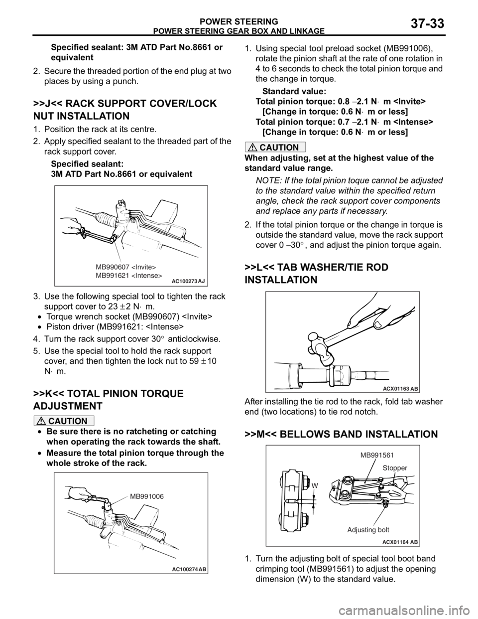
2. Apply specified sealant to the threaded part of the
rack support cover.
Specified sealant:
3M ATD Part No.8661 or equivalent
AC100273
MB990607
MB991621
AJ
3.Use the fo llo wing special to ol to tigh ten the rack
suppor t cover to 2 3
± 2 N⋅m.
•To rque wren ch socket (MB990607 )
•Piston driver (MB9916 21:
4.T u rn the rack suppo rt cover 30° anticlockwise .
5.Use the special tool to hold the r a ck sup port
cove r , and t hen tighten the lock nut to 59
± 10
N
⋅m.
>>K<< T O T A L PINION T O RQUE
ADJUSTMENT
CAUTION
•Be sure there is no ratcheting or catching
when operating the rack towards the shaft.
•
AC100274 AB
MB991006
Measure the total pinion torque through the
whole stroke of the rack.
1. Using special tool preload socket (MB991006),
rotate the pinion shaft at the rate of one rotation in
4 to 6 seconds to check the total pinion torque and
the change in torque.
Standard value:
Total pinion torque: 0.8 − 2.1 N⋅m
[Change in torque: 0.6 N
⋅m or less]
Total pinion torque: 0.7 − 2.1 N⋅m
[Change in torque: 0.6 N
⋅m or less]
CAUTION
When adjusting, set at the highest value of the
standard value range.
NOTE: If the total pinion toque cannot be adjusted
to the standard value within the specified return
angle, check the rack support cover components
and replace any parts if necessary.
2. If the total pinion torque or the change in torque is outside the standard value, move the rack support
cover 0
− 30°, and adjust the pinion torque again.
>>L<< TAB WASHER/TIE ROD
INSTALLATION
ACX01163 AB
After installing the tie rod to the rack, fold tab washer
end (two locations) to tie rod notch.
>>M<< BELLOWS BAND INSTALLATION
ACX01164 AB
W MB991561
Adjusting bolt Stopper
1. Turn the adjusting bolt of special tool boot band
crimping tool (MB991561) to adjust the opening
dimension (W) to the standard value.