ECU MITSUBISHI LANCER 2006 Service Manual
[x] Cancel search | Manufacturer: MITSUBISHI, Model Year: 2006, Model line: LANCER, Model: MITSUBISHI LANCER 2006Pages: 800, PDF Size: 45.03 MB
Page 264 of 800
POWER STEERING GEAR BOX AND LINKAGE
POWER STEERING37-34
NOTE: The dimension (W) is adjusted by approxi-
mately 0.7 mm per one turn.
NOTE: Do not turn the adjusting bolt more than
one turn.
Standard value (W): 2.9 mm
adjusting bolt.
adjusting bolt.
CAUTION
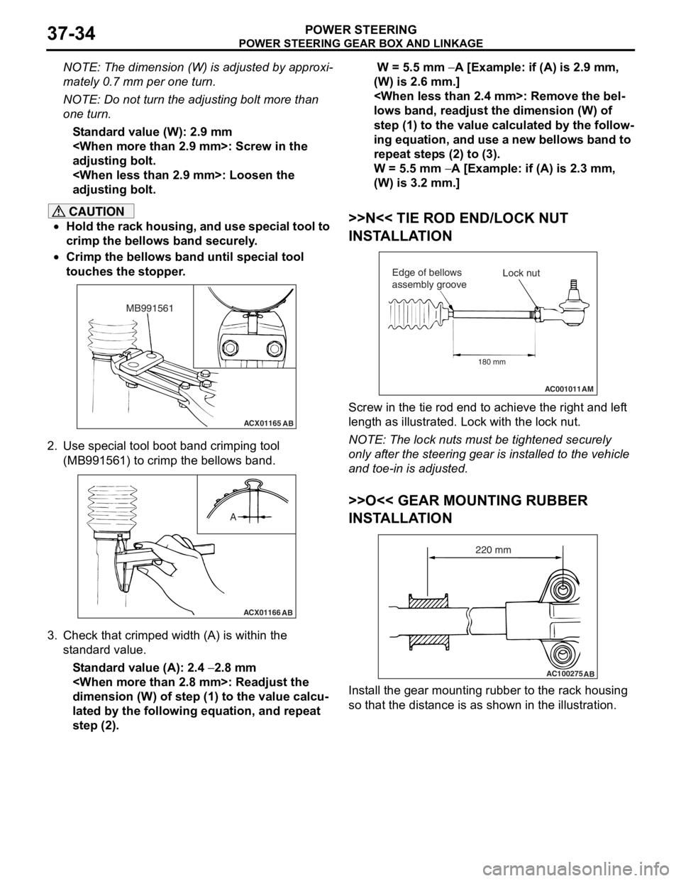
•Hold the rack housing, and use special tool to
crimp the bellows band securely.
•
ACX01165AB
MB991561
Crimp the bellows band until special tool
touches the stopper.
2. Use special tool boot band crimping tool (MB991561) to crimp the bellows band.
ACX01166 AB
A
3. Check that crimped width (A) is within the
standard value.
Standard value (A): 2.4 − 2.8 mm
dimension (W) of step (1) to the value calcu
-
lated by the following equation, and repeat
step (2).
W = 5.5 mm − A [Example: if (A) is 2.9 mm,
(W) is 2.6 mm.]
lows band, readjust the dimension (W) of
step (1) to the value calculated by the follow
-
ing equation, and use a new bellows band to
repeat steps (2) to (3).
W = 5.5 mm − A [Example: if (A) is 2.3 mm,
(W) is 3.2 mm.]
>>N<< TIE ROD END/LOCK NUT
INSTALLATION
AC001011 AM
Lock nut
Edge of bellows
assembly groove
180 mm
Screw in the tie rod end to achieve the right and left
length as illustrated. Lock with the lock nut.
NOTE: The lock nuts must be tightened securely
only after the steering gear is installed to the vehicle
and toe-in is adjusted.
>>O<< GEAR MOUNTING RUBBER
INSTALLATION
AC100275 AB
220 mm
Install the gear mounting rubber to the rack housing
so that the distance is as shown in the illustration.
Page 306 of 800
Page 309 of 800
ItemIdentification
mark
Front DoorLeft door39L
Right door39R
Rear DoorLeft door40L
Right door40R
DOOR
BODY42-37
>>B<< LOWER SASH INSTALLATION
Securely insert the rear lower sash into the window
rear sash.
>>C<< DOOR INSIDE HANDLE
INSTALLATION
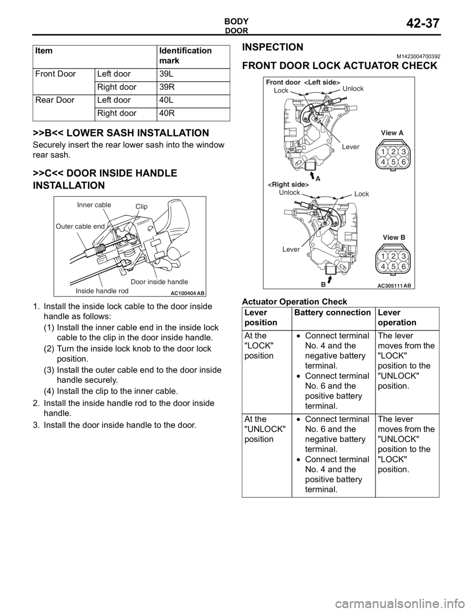
AC100404AB
Clip
Inner cable
Outer cable end
Inside handle rod Door inside handle
1.
In st all the inside lo ck cable to th e doo r inside
ha ndle as fo llo ws:
(1)I nst a ll the inne r cab l e en d in the in sid e lock
cab l e to the clip in th e door inside h andle .
(2)T urn the inside lock knob to the do or lock
positio n.
(3)I nst a ll the outer cable end to the door inside
hand le secure ly .
(4)I nst a ll the clip to the in ner cable .
2.In st all the inside han dle ro d to th e door inside
ha ndle .
3.In st all the do or inside handle to t he doo r .
INSPECTION
M14230047 0039 2
FRONT DOOR LOCK ACTUA T O R CHECK
42
53
6
1
4 2
53
6
1
AC305111B
A
AB
Lock
Unlock
View A
View B
Unlock
Lock
Front door
Lever
Ac tuator Op era t ion Check
Lever
positionBattery connectionLever
operation
At the
"LOCK"
position•Connect terminal
No. 4 and the
negative battery
terminal.
•Connect terminal
No. 6 and the
positive battery
terminal.
The lever
moves from the
"LOCK"
position to the
"UNLOCK"
position.
At the
"UNLOCK"
position•Connect terminal
No. 6 and the
negative battery
terminal.
•Connect terminal
No. 4 and the
positive battery
terminal.
The lever
moves from the
"UNLOCK"
position to the
"LOCK"
position.
Page 325 of 800
KEYLESS ENTRY SYSTEM
BODY42-53
TROUBLESHOOTING
M1428000700287
The keyless entry system is controlled by the Smart
Wiring System (SWS). For troubleshooting, refer to
GROUP 54B, Troubleshooting
P.54B-15 or GROUP
54C, Troubleshooting P.54C-4.
ON-VEHICLE SERVICE
KEYLESS ENTR Y SYSTEM CHECKM1428001400096
Check the system as described below. If the system
does not work, carry out troubleshooting. Refer to
GROUP 54B, Troubleshooting
P.54B-15, refer to
GROUP 54C, Troubleshooting P.54C-4.
•Operate the transmitter to check that the doors
and tailgate can be locked and unlocked.
•Operate the transmitter to check that the answer-
back function works in response to door and tail-
gate
NOTE: The adjustment function allows you to
change the answerback setting as follows. Prior
to that check, confirm which setting is activated.
.
•The hazard warning lamps flash twice when
locked and once when unlocked. The room
lamp flashes twice when locked and illumi
-
nates for 15 seconds when unlocked.
•The hazard warning lamps do not flash when
locked and flash once when unlocked. The
room lamp flashes twice when locked and illu
-
minates for 15 seconds when unlocked.
•The hazard warning lamps flash twice when
locked and do not flash when unlocked. The
room lamp flashes twice when locked and illu
-
minates for 15 seconds when unlocked.
•The hazard warning lamps do not flash when
both locked and unlocked. The room lamp
flashes twice when locked and illuminates for
15 seconds when unlocked.
KEYLESS ENTRY SYS TEM TIMER LOCK
FUNCTION INSPECTION
M1428004000138
Push the transmitter unlock button and check to see
that the doors and tailgate
seconds. If it doesn't, then execute troubleshooting
remedies. Refer to GROUP 54B, Troubleshooting
P.54B-15, refer to GROUP 54C, Troubleshooting
P.54C-4.
ENABLING/DISABLING THE
ANSWERBACK FUNCTION
M1428003200214
If the keyless entry system locks or unlocks the
doors, the room lamp flashes or illuminates, the haz
-
ard warning lamp flashes (hazard answerback func-
tion). The hazard answerback function can be
enabled or disabled according to the following proce
-
dure:
ENABLING/DISABLING THE HAZARD
ANSWERBACK FUNCTION
The hazard answerback function can be enabled or
disabled by one of the two following procedures.
1. Enter the hazard answerback customize mode by performing one of the following steps. If the
ETACS-ECU enters the customize mode, its
buzzer will sound once.
(1) Turn the ignition switch to “LOCK”(OFF) position.
(2) Turn off the hazard warning lamp switch.
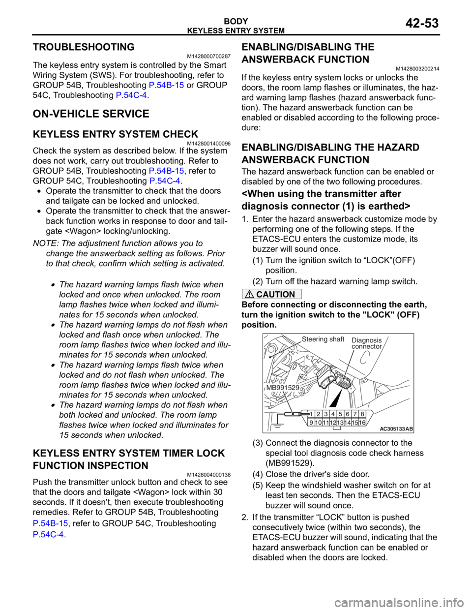
CAUTION
Before connecting or disconnecting the earth,
turn the ignition switch to the "LOCK" (OFF)
position.
AC305133AB
Diagnosis
connector
MB991529Steering shaft
(3) Connect the diagnosis connector to the special tool diagnosis code check harness
(MB991529).
(4) Close the driver's side door.
(5) Keep the windshield washer switch on for at least ten seconds. Then the ETACS-ECU
buzzer will sound once.
2. If the transmitter “LOCK” button is pushed consecutively twice (wit hin two seconds), the
ETACS-ECU buzzer will sound, indicating that the
hazard answerback function can be enabled or
disabled when the doors are locked.
Page 326 of 800
KEYLESS ENTRY SYSTEM
BODY42-54
•Enable the hazard answerback function
when the doors are locked: The
ETACS-ECU buzzer will sound once.
•Disable the hazard answerback function
when the doors are locked: The
ETACS-ECU buzzer will sound twice.
3. If the transmitter “UNLOCK” button is pushed consecutively twice (wit hin two seconds), the
ETACS-ECU buzzer will sound, indicating that the
hazard answerback function can be enabled or
disabled when the doors are unlocked.
•Enable the hazard answerback function
when the doors are unlocked: The
ETACS-ECU buzzer will sound once.
•Disable the hazard answerback function
when the doors are unlocked: The
ETACS-ECU buzzer will sound twice.
4. Exit the hazard answer back customize mode by
observing one of the following steps.
(1) Disconnect diagnosis connector terminal (1) form the earth.
(2) Turn the ignition switch to position other then “LOCK”(OFF), or remove the ignition key.
(3) Open the driver's side door.
(4) Any other warning buzzer output occurs.
NOTE: If any operation is not done for at least three
minutes after the ETACS-ECU has entered the cus
-
tomize mode, the hazard answerback customize
mode will be canceled automatically.
connector>
1. Enter the hazard answerback customize mode by performing one of the following steps. If the
ETACS-ECU enters the customize mode, its
buzzer will sound once.
(1) Turn the ignition switch to “LOCK”(OFF) position.
(2) Turn off the hazard warning lamp switch.
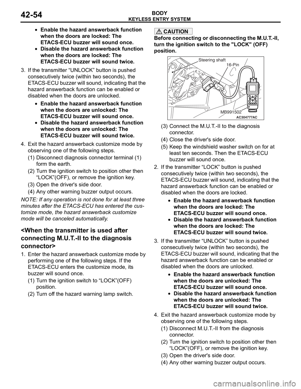
CAUTION
Before connecting or disconnecting the M.U.T.-II,
turn the ignition switch to the "LOCK" (OFF)
position.
AC304777
Steering shaft
ACMB991502
16-Pin
(3) Connect the M.U.T.-II to the diagnosis
connector.
(4) Close the driver's side door.
(5) Keep the windshield washer switch on for at least ten seconds. Then the ETACS-ECU
buzzer will sound once.
2. If the transmitter “LOCK” button is pushed consecutively twice (wit hin two seconds), the
ETACS-ECU buzzer will sound, indicating that the
hazard answerback function can be enabled or
disabled when the doors are locked.
•Enable the hazard answerback function
when the doors are locked: The
ETACS-ECU buzzer will sound once.
•Disable the hazard answerback function
when the doors are locked: The
ETACS-ECU buzzer will sound twice.
3. If the transmitter “UNLOCK” button is pushed consecutively twice (wit hin two seconds), the
ETACS-ECU buzzer will sound, indicating that the
hazard answerback function can be enabled or
disabled when the doors are unlocked.
•Enable the hazard answerback function
when the doors are unlocked: The
ETACS-ECU buzzer will sound once.
•Disable the hazard answerback function
when the doors are unlocked: The
ETACS-ECU buzzer will sound twice.
4. Exit the hazard answer back customize mode by
observing one of the following steps.
(1) Disconnect M.U.T.-II from the diagnosis
connector.
(2) Turn the ignition switch to position other then “LOCK”(OFF), or remove the ignition key.
(3) Open the driver's side door.
(4) Any other warning buzzer output occurs.
Page 327 of 800
KEYLESS ENTRY SYSTEM
BODY42-55
NOTE: If any operation is not done for at least three
minutes after the ETACS-ECU has entered the cus
-
tomize mode, the hazard answerback customize
mode will be canceled automatically.
(MB991824) to the diagnosis connector>
1. Enter the hazard answerback customize mode by
performing one of the following steps. If the
ETACS-ECU enters the customize mode, its
buzzer will sound once.
(1) Turn the ignition switch to “LOCK”(OFF) position.
(2) Turn off the hazard warning lamp switch.
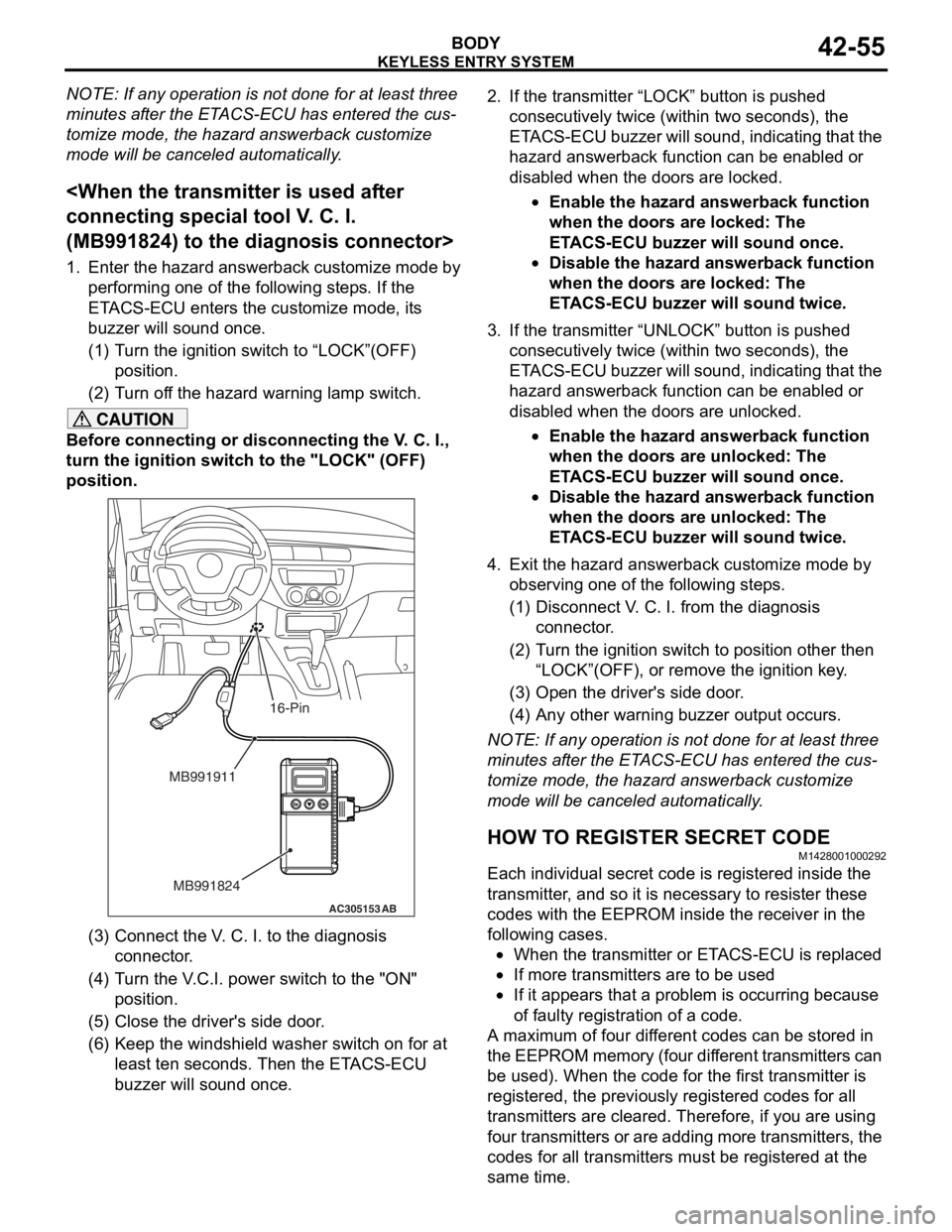
CAUTION
Before connecting or disconnecting the V. C. I.,
turn the ignition switch to the "LOCK" (OFF)
position.
AC305153AB
MB991911
MB991824
16-Pin
(3) Connect the V. C. I. to the diagnosis connector.
(4) Turn the V.C.I. power switch to the "ON" position.
(5) Close the driver's side door.
(6) Keep the windshield washer switch on for at least ten seconds. Then the ETACS-ECU
buzzer will sound once.
2. If the transmitter “LOCK” button is pushed
consecutively twice (wit hin two seconds), the
ETACS-ECU buzzer will sound, indicating that the
hazard answerback function can be enabled or
disabled when the doors are locked.
•Enable the hazard answerback function
when the doors are locked: The
ETACS-ECU buzzer will sound once.
•Disable the hazard answerback function
when the doors are locked: The
ETACS-ECU buzzer will sound twice.
3. If the transmitter “UNLOCK” button is pushed consecutively twice (wit hin two seconds), the
ETACS-ECU buzzer will sound, indicating that the
hazard answerback function can be enabled or
disabled when the doors are unlocked.
•Enable the hazard answerback function
when the doors are unlocked: The
ETACS-ECU buzzer will sound once.
•Disable the hazard answerback function
when the doors are unlocked: The
ETACS-ECU buzzer will sound twice.
4. Exit the hazard answer back customize mode by
observing one of the following steps.
(1) Disconnect V. C. I. from the diagnosis connector.
(2) Turn the ignition switch to position other then
“LOCK”(OFF), or remove the ignition key.
(3) Open the driver's side door.
(4) Any other warning buzzer output occurs.
NOTE: If any operation is not done for at least three
minutes after the ETACS-ECU has entered the cus
-
tomize mode, the hazard answerback customize
mode will be canceled automatically.
HOW TO REGISTER SECRET CODE
M1428001000292
Each individual secret code is registered inside the
transmitter, and so it is necessary to resister these
codes with the EEPROM insi de the receiver in the
following cases.
•When the transmitter or ETACS-ECU is replaced
•If more transmitters are to be used
•If it appears that a probl em is occurring because
of faulty registration of a code.
A maximum of four different codes can be stored in
the EEPROM memory (four different transmitters can
be used). When the code for the first transmitter is
registered, the previously registered codes for all
transmitters are cleared. Therefore, if you are using
four transmitters or are adding more transmitters, the
codes for all transmitters must be registered at the
same time.
Page 351 of 800
AC403580AD
3.5 mm
3.5 mm 5.0
mm 7.0
mm3.5 mm
3.5 mm
3.5 mm
Tape overlap:
3.0 mm
Tape overlap:
3.0 mm
3.5 mm
RH only
RH onlyRH only
Backing paper
cut-lineTape perforate-
lineTape perforate-
line
Backing paper
cut-line
Backing paper
cut-line
: Tape locating points: T-stud for door opening weatherstrip attaching locations (5 pieces in all). Tape perforate-
line
Front door sash
tape upperRear door sash
tape front
Rear door sash
tape upperFront door sash
tape rear
DOOR S
A SH T A PE
EXTERIOR51-19
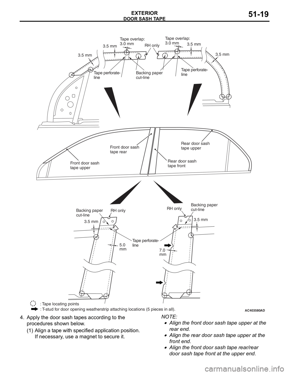
4.App l y t he doo r sash t apes according to t he
pro c ed ures shown b e low .
(1) A lign a t ape with specified a pplication p o sition.
If necessary , u s e a magn et to secu re it.
NOTE: .
•Align the fro n t door sash t ape up per at the
rear en
d.
•Align the rea r door sash t a pe upp er at th e
front en
d.
•Align the fro n t door sash t ape rea r /rear
door sash
t a pe front at the upper e nd.
Page 352 of 800
DOOR SASH TAPE
EXTERIOR51-20
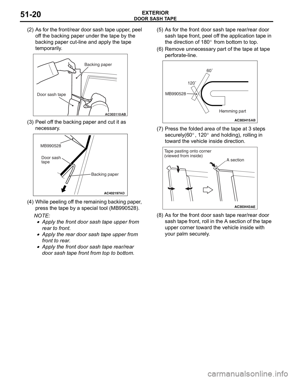
(2) As for the front/rear door sash tape upper, peel off the backing paper under the tape by the
backing paper cut-line and apply the tape
temporarily.
AC303110AB
Backing paper
Door sash tape
(3) P eel o f f th e backin g p aper a nd cu t it a s
necessary .
AC402197AD
MB990528
Backing paper
Door sash
tape
(4
) W hi le pe el in g o f f th e re mai n in g ba ck in g p a pe r ,
press the t a pe by a special to ol (MB99052 8).
NOTE: .
•Apply the fro n t doo r sash t ape u pper fro m
rear to f
r ont.
•Apply the rea r door sash t ape up per from
front to
rear .
•Apply the fro n t doo r sash t ape re ar/rear
door sash
t a p e front from top to b o ttom.
(5) A s fo r the fro n t door sash t ape rea r /rear do or
sash t a pe front, pee l of f the ap plication t a pe in
the d i rection of 180
° from bottom to top.
(6) R emove un nece ssa ry p a rt o f the t ape at t ape
perfo rate-line.
AC303415 AB
MB990528 120˚60˚
Hemming part
(7) P ress the f o lded area o f the t ape at 3 step s
securely(60
°, 12 0° and holding ), rolling in
toward t
he ve
hicle inside direction.
AC303443 AE
A section
Tape pasting onto corner
(viewed from inside)
(8) A s fo r the fro n t door sash t ape rea r /rear do or
sa sh t a pe fro n t, ro ll in t h e A section of th e t a pe
uppe r corn er toward t he ve hicle inside with
you r p a lm sec u rely .
Page 355 of 800
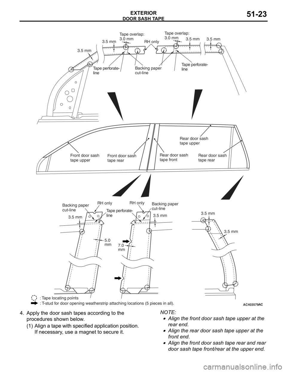
AC403579AC
3.5 mm
3.5 mm 3.5 mm
5.0
mm 7.0
mm 3.5 mm
3.5 mm
3.5 mm
3.5 mm
Tape overlap:
3.0 mm
Tape overlap:
3.0 mm
3.5 mm
RH only
RH onlyRH only
Backing paper
cut-lineTape perforate-
lineTape perforate-
line
Backing paper
cut-lineBacking paper
cut-line
: Tape locating points
: T-stud for door opening weatherstrip attaching locations (5 pieces in all). Tape perforate-
line
Front door sash
tape upperRear door sash
tape front
Rear door sash
tape upper
Rear door sash
tape rearFront door sash
tape rear
DOOR S
A SH T A PE
EXTERIOR51-23
4.App l y t he doo r sash t apes according to t he
pro c ed ures shown b e low .
(1) A lign a t ape with specified a pplication p o sition.
If necessary , u s e a magn et to secu re it.
NOTE: .
•Align the fro n t door sash t ape up per at the
rear en
d.
•Align the rea r door sash t a pe upp er at th e
front en
d.
•Align the front door sash t a p e rea r and rear
door sash
t a pe front /rear at the up per end .
Page 356 of 800
DOOR SASH TAPE
EXTERIOR51-24
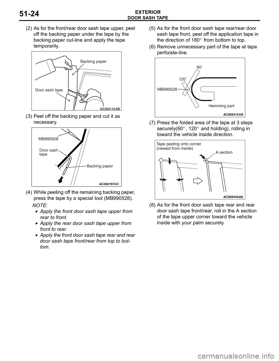
(2) As for the front/rear door sash tape upper, peel off the backing paper under the tape by the
backing paper cut-line and apply the tape
temporarily.
AC303110AB
Backing paper
Door sash tape
(3) P eel o f f th e backin g p aper a nd cu t it a s
necessary .
AC402197AD
MB990528
Backing paper
Door sash
tape
(4
) W hi le pe el in g o f f th e re mai n in g ba ck in g p a pe r ,
press the t a pe by a special to ol (MB99052 8).
NOTE: .
•Apply the fro n t doo r sash t ape u pper fro m
rear to f
r ont.
•Apply the rea r door sash t ape up per from
front to
rear .
•Apply the front door sash t ape rear and rear
door sash
t a p e front /rear from top to bot
-
tom.
(5) A s fo r the fro n t door sash t ape rea r /rear do or
sash t a pe front, pee l of f the ap plication t a pe in
the d i rection of 180
° from bottom to top.
(6) R emove un nece ssa ry p a rt o f the t ape at t ape
perfo rate-line.
AC303415 AB
MB990528 120˚60˚
Hemming part
(7) P ress the f o lded area o f the t ape at 3 step s
securely(60
°, 12 0° and holding ), rolling in
toward t
he ve
hicle inside direction.
AC303443 AE
A section
Tape pasting onto corner
(viewed from inside)
(8) A s fo r the fro n t door sash t ape rea r and re ar
door sash t ape fro n t/rear , roll in th e A section
of th e t a pe upp er co rner toward the vehicle
inside with your p a lm se curely .