ECU MITSUBISHI LANCER 2006 Repair Manual
[x] Cancel search | Manufacturer: MITSUBISHI, Model Year: 2006, Model line: LANCER, Model: MITSUBISHI LANCER 2006Pages: 800, PDF Size: 45.03 MB
Page 360 of 800

WINDSHIELD WIPER AND WASHER
EXTERIOR51-28
WINDSHIELD WIPER AND WASHER
GENERAL INFORMATIONM1511000100514
WINDSHIELD WIPER AND WASHER
OPERATION
Windshield Low-speed (and High-speed)
Wiper Operation
•If the windshield low-speed wiper switch is turned
to the ON position with the ignition switch at the
"ACC" or "ON" position, the column switch sends
a low-speed wiper ON and high-speed wiper OFF
signals to the front-ECU. This turns the wiper sig
-
nal on and the wiper speed control relay off
(low-speed), causing the wipers to operate at
low-speed.
•If the windshield high-speed wiper switch is
turned to the ON position, the column switch
sends a low-speed wiper OFF and high-speed
wiper ON signals to the front-ECU. This turns
both the wiper signal and the wiper speed control
relay on (high-speed), causing the wipers to
operate at high-speed.
NOTE: The windshield wiper speed is switchable
with the built-in wiper speed control relay.
High-speed operations take place when the wiper
speed control relay is set to "ON" and low-speed
operations take place when the wiper speed control
relay is set to "OFF".
Windshield Intermittent Wiper Operation
The ETACS-ECU calculates the wiper operation
interval according to the voltage signal sent from the
column switch. Then the ETACS-ECU sends a signal
to the front-ECU. The front-ECU determines the
wiper operation interval and turns on the wiper relay
signal relay. This causes the wiper auto stop relay to
turn on. Then the wiper auto stop relay will turn off
after the wipers reach the park position. This causes
the wiper signal relay and then the wipers to turn off.
If the wiper signal relay remains off for the wiper
operation interval, the relay turns on again, causing
the wipers to operate in intermittent mode.
Windshield Mist Wiper Operation
•If the windshield mist wipe r switch is turned to the
ON position with the ignition switch at the "ACC"
or "ON" position, the mist wiper high-speed oper
-
ation signal is sent to the front-ECU. This signal
turns on the wiper speed control relay, causing
the wipers to work at high-speed while the mist
switch is on.
•While the windshield mist wiper switch remains
turned on when the intermittent mode is still work
-
ing, the wipers work as the mist wiper. However,
the wipers return to the intermittent mode again
when the switch is changed back to "INT" posi
-
tion.
•To prevent the windshield mist wiper from operat-
ing when the windshield wiper switch is turned
OFF, the windshield mist wiper does not work for
0.5 second after the windshi eld intermittent wiper
switch, the windshield low-speed wiper switch
and the windshield high-speed wiper switch are
turned OFF.
Windshield Washer Operation
•If the windshield washer switch is turned to ON
position with the ignition sw itch at "ACC" or "ON"
position, the windshield wa sher ON signal is sent
to the front-ECU. After 0.3 second, the windshield
wiper signal turns on. After the windshield washer
switch signal turns off, the windshield wiper signal
turns off in three seconds.
•If the windshield washer switch is turned on while
the windshield wiper is at intermittent mode,
when the windshield washer switch is turned OFF
within 0.2 second, the wiper works only once to
perform mist operation by the windshield washer
switch. When the ON condi tion of the windshield
washer switch continues more than 0.2 second,
the wiper performs the same movement as nor
-
mal condition from the time when 0.2 second has
elapsed and then returns to the intermittent
motion.
SERVICE SPECIFICATION
M1511000300325
ItemStandard value
Windshield wiper blade park position mm34 ± 5
Page 362 of 800
MB991529
WINDSHIELD WI PER AND W A SHER
EXTERIOR51-30
TROUBLESHOOTING
M151 1 0007 0032 3
The windshield wiper and washe r are controlled b y
the Sma
r t Wiring System (SWS). For tro ubleshoo t
-
ing, refer to GROUP 54B, T r ouble s ho oting P.54B-15
or GROUP 54 C, T r oublesho oting P.54C-4.
NOTE: Eve n when th e ET ACS-ECU h a s fa ile d, the
windsh
i eld wiper can work at low spe ed as fail-safe
mode
. (Normally , th e windshie l d wip e r opera t es
wh
en t
h e ign i tio n swit ch i s at th e "ACC" pos itio n. Bu t,
if it
enters the fa il-safe mode, the wip e r can opera t e
only when th e ign i tio n switch is at t he "ON" p o sition. )
ON-VEHICLE SERV ICE
M151 1 0008 0046 1
WI NDSHIELD INTERMITTENT WIPER
INSPECTION
1. If the win d shield intermitte nt wiper interval
a d justing knob is operate d , the wiper interval
should ch ange.
2.Holding the win d shield intermitte nt wiper interval
a d justing kno b , input t he simu lated ve hicle speed
with M.U.T . -I I / II I a nd check th at the wipe r inte rval
chang es as the v ehicle spe ed changes.
3.If not, carry o u t the troublesho oting (Refer to
GROUP 54B, T r ou bleshoot ing
P.54B-15 or
GROUP 54C, T r ou bleshooting P.54C-4).
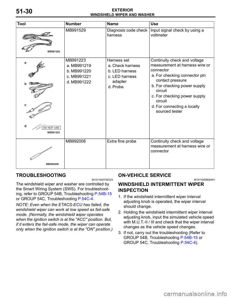
MB991529Diagnosis code check
harn
e ssInput sign al check by using a
voltm
e ter
MB991223
a
d c
b
DO NOT USE
BA
MB991 223
a. MB99121 9
b. MB99122 0
c.MB99122 1
d. MB99122 2
Harness set
a.Check harne ss
b.LED harness
c.LED harness
adapt er
d.Probe
Con t inuity check an d vo lt age
measurement at
harness wire or
conn
ector
a.Fo r che cking connector pin
cont act pressure
b.Fo r che cking po we r sup p ly
circuit
c. Fo r che cking po we r sup p ly
circuit
d.Fo r con necting a locally
sourced tester
MB992006
MB992 006Extra fine probeCont inuity check an d vo lt age
measurement at
harness wire or
conn
ector
Tool Nu mber Name Use
Page 367 of 800
REAR WIPER AND WASHER
EXTERIOR51-35
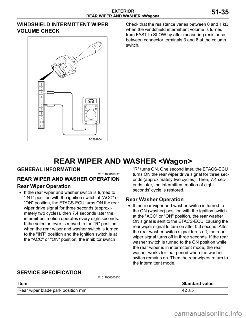
WINDSHIELD INTERMITTENT WIPER
VOLUME CHECK
1
6
8
11 10 9 7 5 4 3
2
AC201004
Ch
eck tha t the resist ance varie s between 0 a nd 1 kΩ
wh
en the
windshield int
e
rmittent volume is turn
ed
from F
A
ST
to SLOW by a
f
te
r mea
s
uring resist
an
ce
between conne
ctor
terminals 3 an
d 6 at
the column
switc
h
.
REAR WIPER AND W A SHER
GENERAL INFORMAT IONM151 1 0001 0052 5
REAR WIPER AND W A SHER OPERA T ION
Rear W i p e r O p eration
•If the rear wiper and washe r switch is turne d to
"INT" position
wit h th e ignition switch at "ACC" or
"ON" po
siti on, t he ET ACS-ECU t u rn s ON t he re ar
wipe
r drive signal for thre e se cond s (ap p roxi
-
mately two cycles), then 7 . 4 se cond s la ter the
int
e rmit tent mot i on o perates every eigh t seco nds.
If th
e se lector lever is moved to the "R" p o sition
when t
he rear wiper an d washe r switch is turn ed
to t
he "INT" position an d the ignit i on switch is at
the
"ACC" or "ON" positio n, the inhibito r switch "R" tu rns ON. One second late r , the ET ACS-ECU
turn s ON th e rear wip e r drive signal for thre e sec
-
ond
s (ap p roximat e ly two cycle s ). Th en, 7.4 sec-
onds later , th e inte rmittent motio n of eight
sec
o nds ' cy cle is restored.
Rear W a sher Operatio n
•If the rear wiper and washe r switch is turne d to
the
ON (washer) position wi th the ignition switch
at t
he "ACC" or "ON" po sit i on, t he rear wa sher
ON signal is sent to the ET
ACS-ECU, causing the
re
ar wipe r sign al to tu rn on a f ter 0 . 3 seco nd . Af te r
the
rear washer switch sign al tu rns o f f, the rear
wipe
r signa l t u rns of f in thre e seco nds. If the rear
washer switch is tu
rned to the ON position while
the
rear wipe r is in intermitten t mod e , the rear
washer works for th
at period when the washer
switch
rema ins on. Then the rea r wipe rs ret u rn to
the
intermitte nt mode.
SERV ICE SPECIFICA T ION
M151 1 0003 0033 6
ItemStandard value
Rear wiper blade park position mm42 ± 5
Page 375 of 800
DOOR MIRROR
EXTERIOR51-43
DOOR MIRROR
GENERAL INFORMATIONM1511000100536
DOOR MIRROR OPERATION
Remote Controlled Mirror Operation
•The mirror on the door mirror moves up/down
and left/right by operating the remote controlled
door mirror switch when the ignition switch is in
the "ON" or "ACC" position.
Heated Door Mirror operation
•The defogger relay switch is activated (ON) by
turning on the A/C-ECU built-in defogger switch
when the ignition switch is in the "ON" position.
When the defogger relay is turned ON, power is
supplied to the defogger and door mirror, and the
heater of the door mirror (heated door mirror)
starts operations. The defogger comes with a
timer function and will automatically turn OFF the
switch approximately 11 minutes after the defog
-
ger switch is turned ON. The heated door mirror
operations are also terminated along with the
defogger, at this time.
SERVICE SPECIFICATION
M1511000300347
ItemStandard value
Heated door mirror operation current Ω5.9 − 7.8
SPECIAL TOOL
M1511000601103
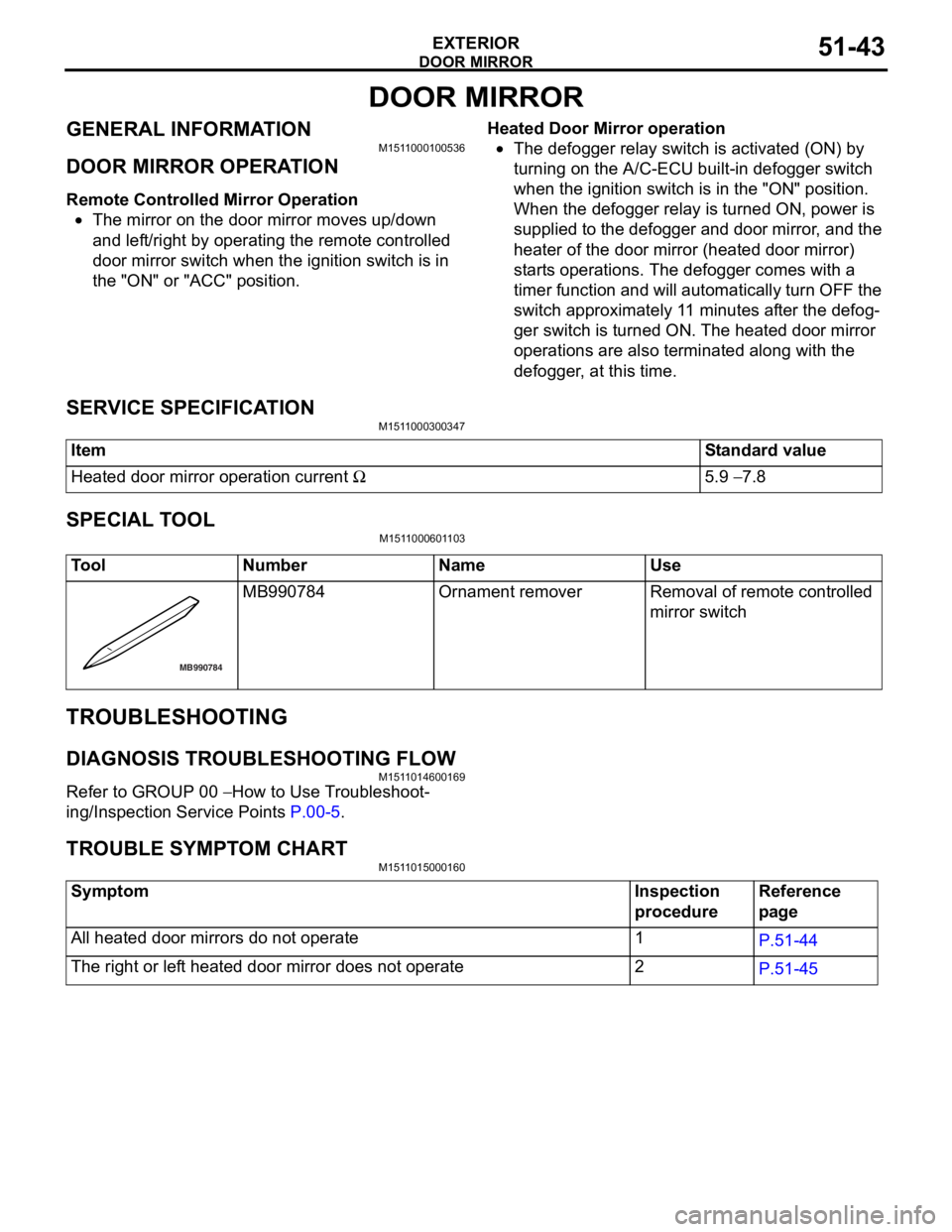
ToolNumberNameUse
MB990784
MB990 784Ornament removerRemoval of remote controlled
mirror switch
TROUBLESHOOTING
DIAGNOSIS TROUBLESHOOTING FLOW
M151 1 0146 0016 9
Refe r to GROUP 00 − How to Use T r o ubleshoot-
ing/Inspectio n Service Point s P.00-5.
TR OUBLE SYM PT OM CHARTM151 1 0150 0016 0
SymptomInspection
procedureReference
page
All heated door mirrors do not operate1P.51-44
The right or left heated door mirror does not operate2P.51-45
Page 391 of 800
70-1
GROUP 70
COMPONENT
LOC ATIONS
CONTENTS
ECU . . . . . . . . . . . . . . . . . . . . . . . . . .70-2
RELAY . . . . . . . . . . . . . . . . . . . . . . . .70-5
SENSOR. . . . . . . . . . . . . . . . . . . . . . .70-6
FUSIBLE LINK AND FU SE . . . . . . . .70-11
EARTH CABLE . . . . . . . . . . . . . . . . .70-12
SOLENOID VALVE . . . . . . . . . . . . . . .70-13
DIODE . . . . . . . . . . . . . . . . . . . . . . . . .70-14
EARTH . . . . . . . . . . . . . . . . . . . . . . . .70-15
INSPECTION CONNECTOR AND
SPARE CONNECTOR . . . . . . . . . . . .70-19
Page 392 of 800
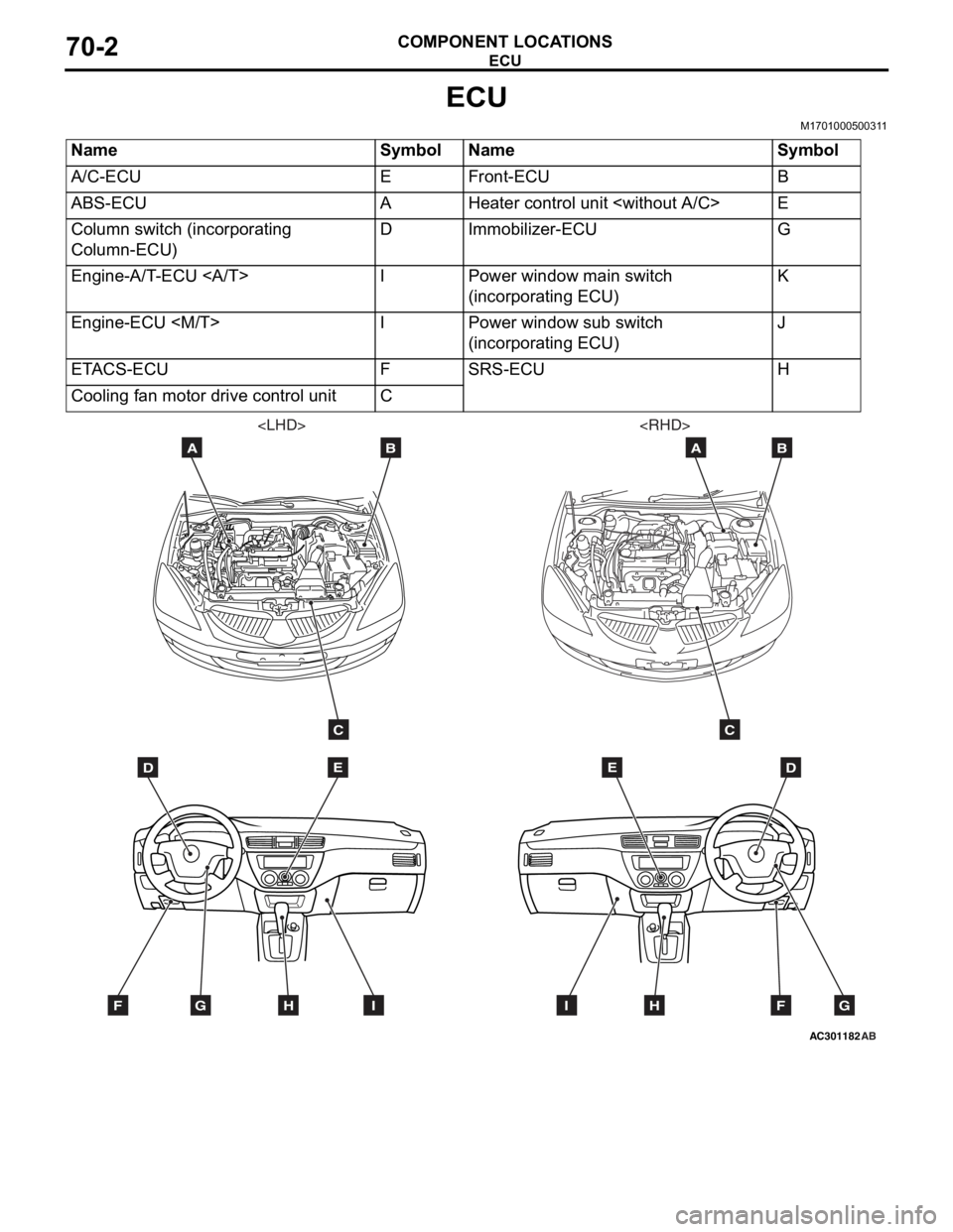
ECU
COMPONENT LOCATIONS70-2
ECU
M1701000500311
NameSymbolNameSymbol
A/C-ECUEFront-ECUB
ABS-ECUAHeater control unit
Column switch (incorporating
Column-ECU)DImmobilizer-ECUG
Engine-A/T-ECU IPower window main switch
(incorporating ECU)K
Engine-ECU
(incorporating ECU)J
ETACS-ECUFSRS-ECUH
Cooling fan motor drive control unitC
AC301182
DE
AB
C
FGHI
AB
DE
AB
C
FGHI
Page 393 of 800
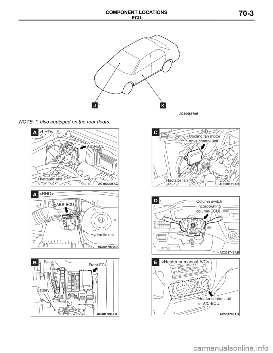
AC304537
JK*
AE
ECU
COMPONENT LOCA TIONS70-3
NOTE: *: also eq uipp ed on the rear doors.
AC100209AC
A
ABS-ECU
Hydraulic unit
AC206790
A
AD
ABS-ECU
Hydraulic unit
AC301728AB
BFront-ECU
Battery
AC300571
C
ACRadiator fan
Cooling fan motor
drive control unit
AC301746
DColumn switch
(incorporating
column-ECU)
AB
AC501783AB
E
Heater control unit
or A/C-ECU
Page 394 of 800
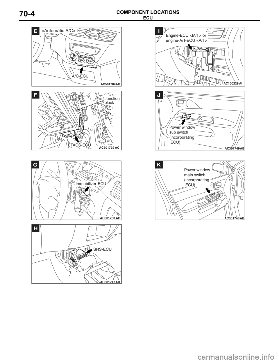
AC501784AB
E
A/C-ECU
AC301739AC
F
ETACS-ECU
Junction
block
AC301733AB
Immobilizer-ECU
G
AC301747AB
SRS-ECU
H
AC100229AI
Engine-ECU
engine-A/T-ECU I
AC301749AB
Power window
sub switch
(incorporating
ECU)
J
AC301748AB
Power window
main switch
(incorporating
ECU)
K
ECU
COMPONENT LOCA
TIONS70-4
Page 400 of 800
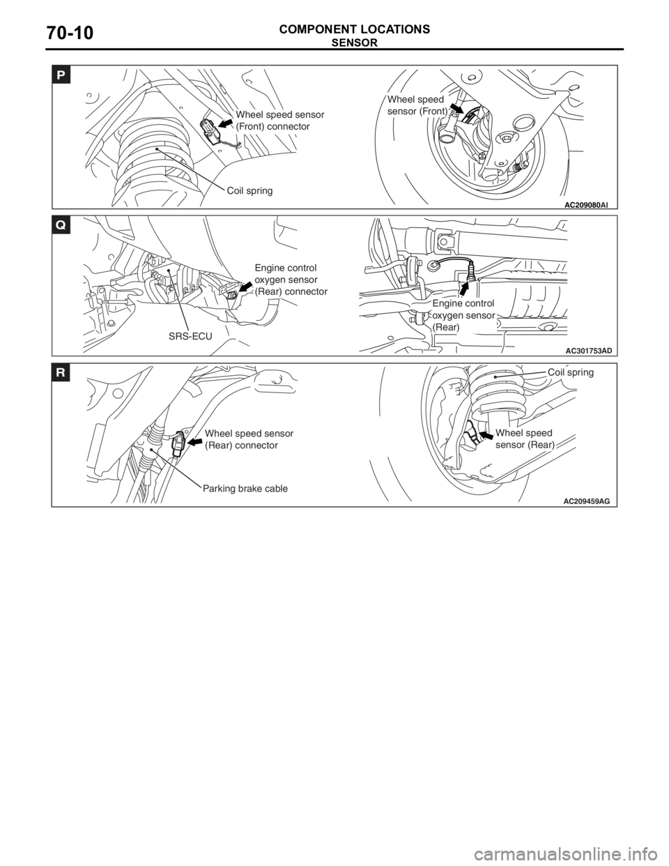
AC209080
P
AI
Wheel speed sensor
(Front) connector
Coil spring
Wheel speed
sensor (Front)
AC301753AD
SRS-ECU
Q
Engine control
oxygen sensor
(Rear) connector
Engine control
oxygen sensor
(Rear)
AC209459
R
Wheel speed sensor
(Rear) connector
Parking brake cable
Coil spring
AG
Wheel speed
sensor (Rear)
SE NSOR
COMPONENT LOCA TIONS70-10
Page 408 of 800
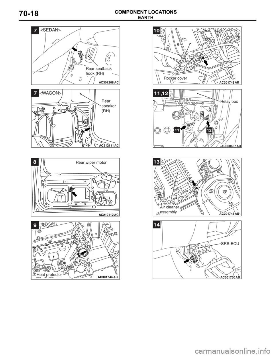
AC301208
7
AC
Rear seatback
hook (RH)
AC212111
7
AC
Rear
speaker
(RH)
AC212112AC
8Rear wiper motor
AC301744AB
9
Heat protector
AC301743AB
10
Rocker cover
AC300437
1112
,
1112
AD
Relay box
AC301745
13
AB
Air cleaner
assembly
AC301750AB
14
SRS-ECU
EARTH
COMPONENT LOCA TIONS70-18