front MITSUBISHI LANCER 2006 Manual Online
[x] Cancel search | Manufacturer: MITSUBISHI, Model Year: 2006, Model line: LANCER, Model: MITSUBISHI LANCER 2006Pages: 800, PDF Size: 45.03 MB
Page 309 of 800
ItemIdentification
mark
Front DoorLeft door39L
Right door39R
Rear DoorLeft door40L
Right door40R
DOOR
BODY42-37
>>B<< LOWER SASH INSTALLATION
Securely insert the rear lower sash into the window
rear sash.
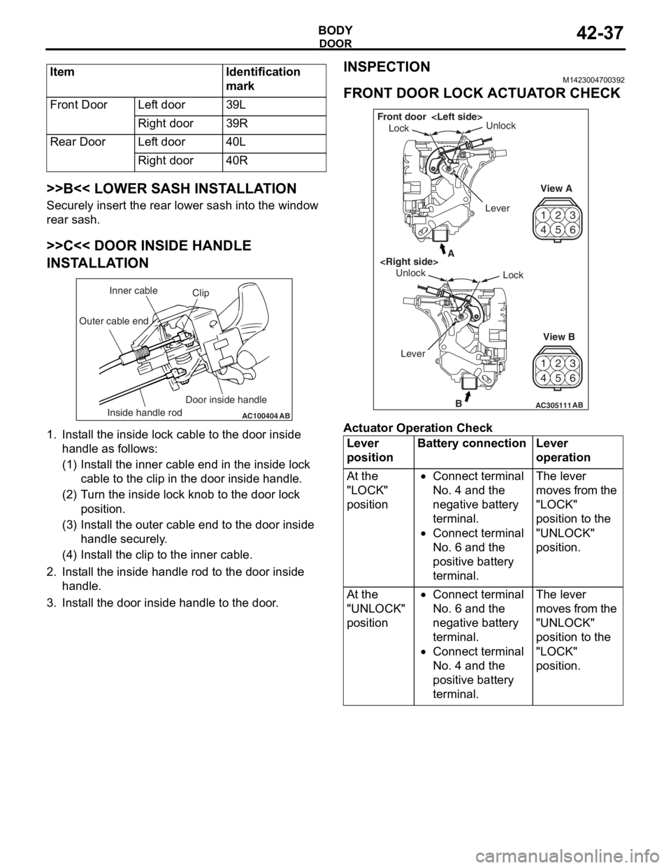
>>C<< DOOR INSIDE HANDLE
INSTALLATION
AC100404AB
Clip
Inner cable
Outer cable end
Inside handle rod Door inside handle
1.
In st all the inside lo ck cable to th e doo r inside
ha ndle as fo llo ws:
(1)I nst a ll the inne r cab l e en d in the in sid e lock
cab l e to the clip in th e door inside h andle .
(2)T urn the inside lock knob to the do or lock
positio n.
(3)I nst a ll the outer cable end to the door inside
hand le secure ly .
(4)I nst a ll the clip to the in ner cable .
2.In st all the inside han dle ro d to th e door inside
ha ndle .
3.In st all the do or inside handle to t he doo r .
INSPECTION
M14230047 0039 2
FRONT DOOR LOCK ACTUA T O R CHECK
42
53
6
1
4 2
53
6
1
AC305111B
A
AB
Lock
Unlock
View A
View B
Unlock
Lock
Front door
Lever
Ac tuator Op era t ion Check
Lever
positionBattery connectionLever
operation
At the
"LOCK"
position•Connect terminal
No. 4 and the
negative battery
terminal.
•Connect terminal
No. 6 and the
positive battery
terminal.
The lever
moves from the
"LOCK"
position to the
"UNLOCK"
position.
At the
"UNLOCK"
position•Connect terminal
No. 6 and the
negative battery
terminal.
•Connect terminal
No. 4 and the
positive battery
terminal.
The lever
moves from the
"UNLOCK"
position to the
"LOCK"
position.
Page 311 of 800
DOOR
BODY42-39
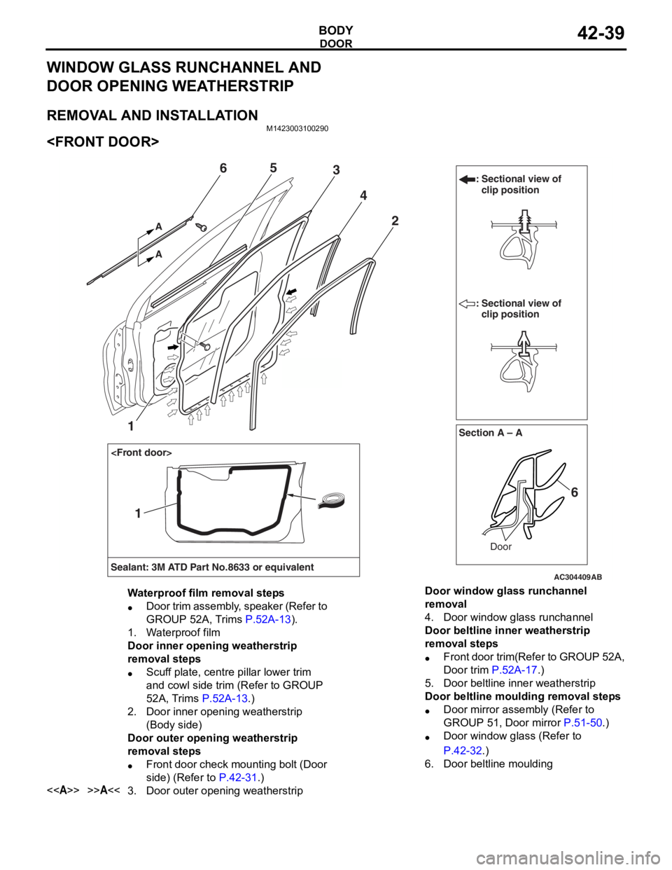
WINDOW GLASS RUNCHANNEL AND
DOOR OPENING WEATHERSTRIP
REMOVAL AND INSTALLATION
M1423003100290
AC304409AB
Section A – A
Sealant: 3M ATD Part No.8633 or equivalent Door
: Sectional view of
clip position
: Sectional view of clip position
6
2
1
4
365
A A
1
Waterproof film removal steps
•Door trim assembly, speaker (Refer to
GROUP 52A, Trims
P.52A-13).
1.Waterproof film
Door inner opening weatherstrip
removal steps
•Scuff plate, centre pillar lower trim
and cowl side trim (Refer to GROUP
52A, Trims
P.52A-13.)
2.Door inner opening weatherstrip
(Body side)
Door outer opening weatherstrip
removal steps
•Front door check mounting bolt (Door
side) (Refer to
P.42-31.)
<>>>A<<3.Door outer opening weatherstrip
Door window glass runchannel
removal
4.Door window glass runchannel
Door beltline inner weatherstrip
removal steps
•Front door trim(Refer to GROUP 52A,
Door trim
P.52A-17.)
5.Door beltline inner weatherstrip
Door beltline moulding removal steps
•Door mirror assembly (Refer to
GROUP 51, Door mirror
P.51-50.)
•Door window glass (Refer to
P.42-32.)
6.Door beltline moulding
Page 315 of 800
TRUNK LID
BODY42-43
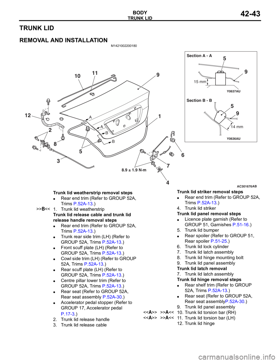
TRUNK LID
REMOVAL AND INSTALLATION
M1421002200180
AC301676
Y0636AU
Y0637AU
AB
8.9 ± 1.9 N·m
A
AB
B 15 mm
14 mm
Section A - A
Section B - B
9
5
6
4
12
9
59
7
11
10
8 3 5 1
2
Trunk lid weatherstrip removal steps
•Rear end trim (Refer to GROUP 52A,
Trims
P.52A-13.)
>>B<<1.Trunk lid weatherstrip
Trunk lid release cable and trunk lid
release handle removal steps
•Rear end trim (Refer to GROUP 52A,
Trims
P.52A-13.)
•Trunk rear side trim (LH) (Refer to
GROUP 52A, Trims
P.52A-13.)
•Front scuff plate (LH) (Refer to
GROUP 52A, Trims
P.52A-13.)
•Cowl side trim (LH) (Refer to GROUP
52A, Trims
P.52A-13.)
•Rear scuff plate (LH) (Refer to
GROUP 52A, Trims
P.52A-13.)
•Centre pillar lower trim (Refer to
GROUP 52A, Trims
P.52A-13.)
•Rear seat (Refer to GROUP 52A,
Rear seat assembly
P.52A-30.)
•Accelerator pedal stopper (Refer to
GROUP 17, Accelerator pedal
P.17-3.)
2.Trunk lid release handle
3.Trunk lid release cable
Trunk lid striker removal steps
•Rear end trim (Refer to GROUP 52A,
Trims
P.52A-13.)
4.Trunk lid striker
Trunk lid panel removal steps
•Licence plate garnish (Refer to
GROUP 51, Garnishes
P.51-16.)
5.Trunk lid bumper
•Rear spoiler (Refer to GROUP 51,
Rear spoiler
P.51-25.)
6.Trunk lid lock cylinder
7.Trunk lid latch assembly
8.Trunk lid hinge mounting bolt
9.Trunk lid panel assembly
Trunk lid latch removal
7.Trunk lid latch assembly
Trunk lid hinge removal steps
•Rear shelf trim (Refer to GROUP
52A, Trims
P.52A-13.)
•Rear seat (Refer to GROUP 52A,
Rear seat assembly
P.52A-30.)
9.Trunk lid panel assembly
<>>>A<<10.Trunk lid torsion bar (RH)
<>>>A<<11 .Trunk lid torsion bar (LH)
12.Trunk lid hinge
Page 333 of 800
51-1
GROUP 51
EXTERIOR
CONTENTS
FRONT BUMPER ASSEMBLY . . . . .51-3
ADHESIVE . . . . . . . . . . . . . . . . . . . . . . . . . 51-3
FRONT BUMPER ASSEMBLY . . . . . . . . . . 51-3
REMOVAL AND INSTALLATION . . . . . . . . 51-3
DISASSEMBLY AND REASSEMBLY . . . . . 51-4
REAR BUMPER ASSEMBLY . . . . . .51-6
REMOVAL AND INSTALLATION . . . . . . . . 51-6
DISASSEMBLY AND REASSEMBLY . . . . . 51-7
MOULDINGS . . . . . . . . . . . . . . . . . . .51-8
SPECIAL TOOL . . . . . . . . . . . . . . . . . . . . . 51-8
ADHESIVE . . . . . . . . . . . . . . . . . . . . . . . . . 51-9
MOULDINGS . . . . . . . . . . . . . . . . . . . . . . . 51-9
REMOVAL AND INSTALLATION . . . . . . . . 51-9
SIDE AIR DAM . . . . . . . . . . . . . . . . . .51-14
ADHESIVE . . . . . . . . . . . . . . . . . . . . . . . . . 51-14
SIDE AIR DAM . . . . . . . . . . . . . . . . . . . . . . 51-14
REMOVAL AND INSTALLATION . . . . . . . . 51-14
GARNISHES . . . . . . . . . . . . . . . . . . .51-16
REMOVAL AND INSTALLATION . . . . . . . . 51-16
DOOR SASH TAPE . . . . . . . . . . . . . .51-17
SPECIAL TOOL . . . . . . . . . . . . . . . . . . . . . 51-17
DOOR SASH TAPE . . . . . . . . . . . . . . . . . . 51-17
REMOVAL AND INSTALLATION
REMOVAL AND INSTALLATION
REAR SPOILER
REMOVAL AND INSTALLATION . . . . . . . . 51-25
TAILGATE SPOILER
REMOVAL AND INSTALLATION . . . . . . . . 51-26
ROOF RAIL
REMOVAL AND INSTALLATION . . . . . . . . 51-27
WINDSHIELD WIPER AND
WASHER. . . . . . . . . . . . . . . . . . . . . . .51-28
GENERAL INFORMATION . . . . . . . . . . . . . 51-28
SERVICE SPECIFICATION . . . . . . . . . . . . 51-28
SPECIAL TOOLS . . . . . . . . . . . . . . . . . . . . 51-29
TROUBLESHOOTING . . . . . . . . . . . . . . . . 51-30
ON-VEHICLE SERVICE . . . . . . . . . . . . . . . 51-30
WINDSHIELD WIPER AND WASHER . . . . 51-31
REMOVAL AND INSTALLATION . . . . . . . . 51-31
INSPECTION. . . . . . . . . . . . . . . . . . . . . . . . 51-33
REAR WIPER AND WASHER
GENERAL INFORMATION . . . . . . . . . . . . . 51-35
SERVICE SPECIFICATION . . . . . . . . . . . . 51-35
TROUBLESHOOTING . . . . . . . . . . . . . . . . 51-36
ON-VEHICLE SERVICE . . . . . . . . . . . . . . . 51-36
REAR WIPER AND WASHER . . . . . . . . . . 51-36
REMOVAL AND INSTALLATION . . . . . . . . 51-36
INSPECTION. . . . . . . . . . . . . . . . . . . . . . . . 51-37
Continued on next page
Page 335 of 800
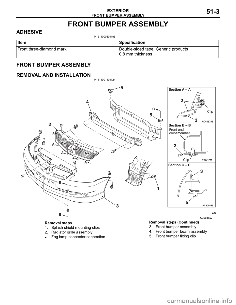
FRONT BUMPER ASSEMBLY
EXTERIOR51-3
FRONT BUMPER ASSEMBLY
ADHESIVEM1511000501195
ItemSpecification
Front three-diamond markDouble-sided tape: Generic products
0.8 mm thickness
FRONT BUMPER ASSEMBLY
REMOVAL AND INSTALLATIONM1511001401124
AC504557
AC300466
Y0534AU
AC405706
AB
2
4
5
5
3 1
C
C
B
B
A
A
A
AA
A
A
A
3
2
Section A – A
3
Clip
Front end
crossmember
Clip
Section B – B
5
3
Section C – C
Removal steps
1.Splash shield mounting clips
2.Radiator grille assembly
•Fog lamp connector connection
3.Front bumper assembly
4.Front bumper beam assembly
5.Front bumper fixing clip
Removal steps (Continued)
Page 336 of 800
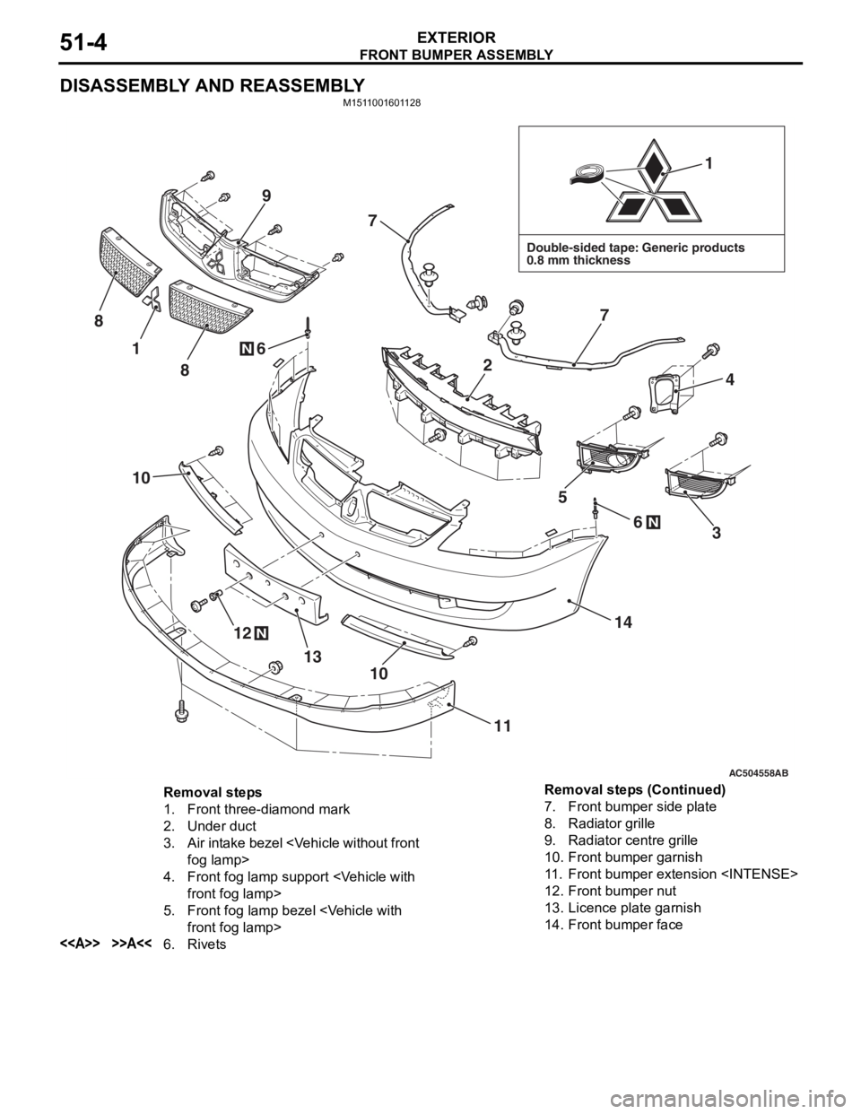
FRONT BUMPER ASSEMBLY
EXTERIOR51-4
DISASSEMBLY AND REASSEMBLY
M1511001601128
AC504558AB
Double-sided tape: Generic products
0.8 mm thickness
1
1
12
13
14
11
10
10
4
7
7
6
6
8
9
8
5
3N
N
N
2
Removal steps
1.Front three-diamond mark
2.Under duct
3.Air intake bezel
4.Front fog lamp sup port
5.Front fog lamp bezel
<>>>A<<6.Rivets
7.Front bumper side plate
8.Radiator grille
9.Radiator centre grille
10.Front bumper garnish
11 .Front bumper extension
12.Front bumper nut
13.Licence plate garnish
14.Front bumper face
Removal steps (Continued)
Page 337 of 800

Page 341 of 800
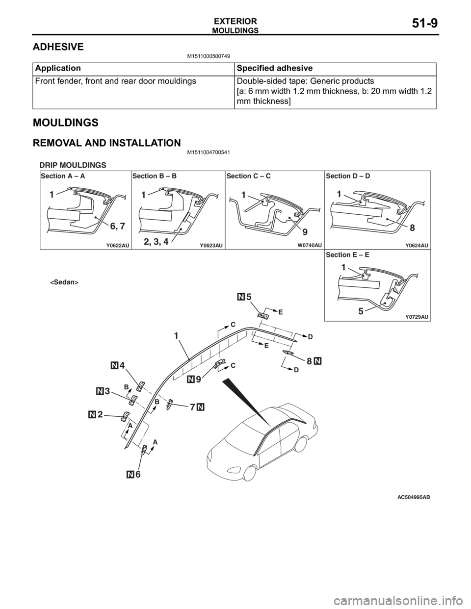
MOULDINGS
EXTERIOR51-9
ADHESIVE
M1511000500749
ApplicationSpecified adhesive
Front fender, front and rear door mouldingsDouble-sided tape: Generic products
[a: 6 mm width 1.2 mm thickness, b: 20 mm width 1.2
mm thickness]
MOULDINGS
REMOVAL AND INSTALLATIONM1511004700541
AC504995
Y0622AU
Y0624AUY0623AU
Y0729AU
W0740AU
Section A – A
DRIP MOULDINGS
Section B – B Section C – C Section D – D
Section E – E
AB
N
N
N
N
N
CC
E E
D
D
B
B
A
A
1
2
6
4
3
5
7
8
9
N
N
N
111
9 8
51
1
6, 7 2, 3, 4
Page 342 of 800
AC304340
1
1
AA
AA
AB
B
B
C
C
C
C
B B
N
N
N
2
N2
4
3
N3
N4
N
6
9
7
N
6N
N
7N
N9
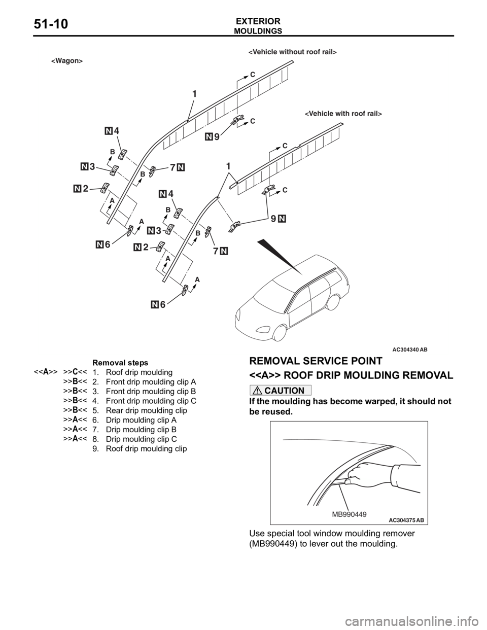
Removal steps
<>>>C<<1.Roof drip moulding
>>B<<2.Front drip moulding clip A
>>B<<3.Front drip moulding clip B
>>B<<4.Front drip moulding clip C
>>B<<5.Rear drip moulding clip
>>A<<6.Drip moulding clip A
>>A<<7.Drip moulding clip B
>>A<<8.Drip moulding clip C
9.Roof drip moulding clip
MO
UL DI N G S
EXTERIOR51-10
REMOVA L SER VICE POINT
<> ROOF DRIP MOULDING REMOV A L
CAUTION
If the moulding has become warped, it should not
be reused.
AC304375MB990449AB
Use special tool window moulding remover
(MB990449) to lever out the moulding.
Page 343 of 800
MOULDINGS
EXTERIOR51-11
INSTALLATION SERVICE POINTS
>>A<< DRIP MOULDING CLIP C/DRIP
MOULDING CLIP B/DRIP MOULDING
CLIP A INSTALLATION
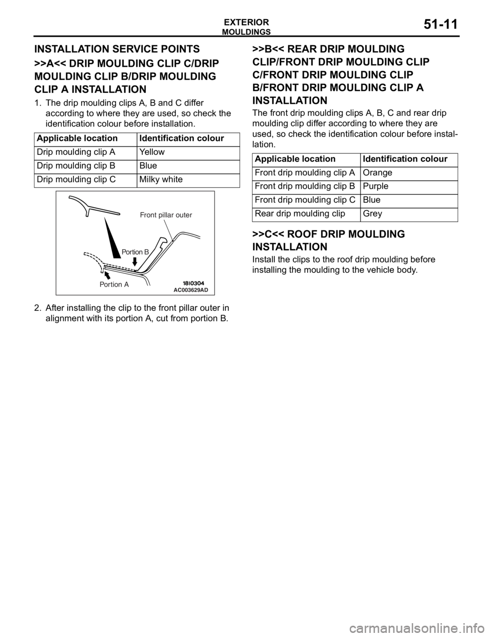
1. The drip moulding clips A, B and C differ according to where they are used, so check the
identification colour before installation.
Applicable locationIdentification colour
Drip moulding clip AYe l l o w
Drip moulding clip BBlue
Drip moulding clip CMilky white
AC003629
Front pillar outer
Portion B
Portion AAD
2. Af ter inst alling the clip to the f r ont pilla r outer in
align m ent with it s portio n A, cu t from portion B.
>>B<< REAR DRIP MOULDING
CLIP/FRONT DRIP MOULDING CLIP
C/FRONT DRIP MOULDING CLIP
B/FRONT DRIP MOULDING CLIP A
INST
ALLA TION
The front drip mou l din g clip s A, B, C an d rear d r ip
moulding
clip dif f er accordin g to where they are
used
, so check th e ide n tification colou r before inst al
-
lation.
Applicable locationIdentification colour
Front drip moulding clip AOrange
Front drip moulding clip BPurple
Front drip moulding clip CBlue
Rear drip moulding clipGrey
>>C<< ROOF DRIP MOULDING
INSTALLA TION
Install the clip s to th e roof d r ip mould i ng before
inst
allin g the moulding to the vehicle body .