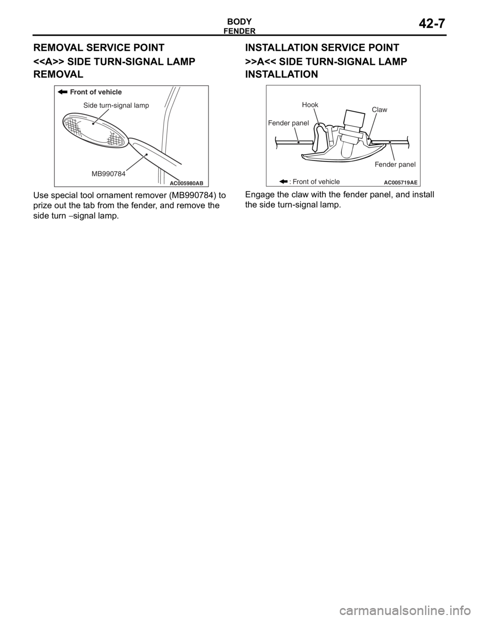
front MITSUBISHI LANCER 2006 Repair Manual
[x] Cancel search | Manufacturer: MITSUBISHI, Model Year: 2006, Model line: LANCER, Model: MITSUBISHI LANCER 2006Pages: 800, PDF Size: 45.03 MB
Page 231 of 800
37-1
GROUP 37
POWER STEERING
CONTENTS
GENERAL INFORMATION . . . . . . . .37-3
SERVICE SPECIFICATIONS . . . . . . .37-6
LUBRICANTS . . . . . . . . . . . . . . . . . .37-7
SEALANTS . . . . . . . . . . . . . . . . . . . .37-7
SPECIAL TOOLS . . . . . . . . . . . . . . . .37-8
ON-VEHICLE SERVICE . . . . . . . . . . .37-11
STEERING WHEEL FREE PLAY CHECK . 37-11
STEERING ANGLE CHECK . . . . . . . . . . . . 37-11
TIE ROD END BALL JOINT TURNING
TORQUE CHECK . . . . . . . . . . . . . . . . . . . . 37-12
STATIONARY STEERING EFFORT
CHECK . . . . . . . . . . . . . . . . . . . . . . . . . . . . 37-12
STEERING WHEEL RETURN TO
CENTRE CHECK . . . . . . . . . . . . . . . . . . . . 37-13
DRIVE BELT TENSION CHECK. . . . . . . . . 37-13
FLUID LEVEL CHECK . . . . . . . . . . . . . . . . 37-13
FLUID REPLACEMENT . . . . . . . . . . . . . . . 37-13
POWER STEERING SYSTEM AIR
BLEEDING . . . . . . . . . . . . . . . . . . . . . . . . . 37-14
OIL PUMP PRESSURE TEST . . . . . . . . . . 37-14
POWER STEERING PRESSURE
SWITCH CHECK . . . . . . . . . . . . . . . . . . . . . 37-15
TIE ROD END BALL JOINT DUST
COVER CHECK . . . . . . . . . . . . . . . . . . . . . 37-15
STEERING COLUMN SHAFT ASSEMBLY
SHOCK ABSORBING MECHANISM
CHECK . . . . . . . . . . . . . . . . . . . . . . . . . . . . 37-15
STEERING WHEEL . . . . . . . . . . . . . .37-17
REMOVAL AND INSTALLATION
REMOVAL AND INSTALLATION
Continued on next page
WARNINGS REGARDING SERVICING OF SUPPLEMENTAL RESTRAINT SYSTEM (SRS) EQUIPPED VEHICLES
WARNING
•Improper service or maintenance of any component of the SRS, or any SRS-related component, can lead to
personal injury or death to service personnel (from inad vertent firing of the air bag) or to the driver and
paassenger (from renderin g the SRS inoperative).
•Service or maintenance of any SRS component or SRS-related component must be performed only at an
authorized MITSUBISHI dealer.
•MITSUBISHI dealer personnel must thoroughly review th is manual, and especially its GROUP 52B - Supplemental
Restraint System (SRS) before begi nning any service or maintenance of any component of the SRS or any
SRS-related component.
NOTE
The SRS includes the following components: SRS air bag control unit, SRS warning light, front impact sensors, air bag module,
clock spring, and interconnecting wiring. Other SRS-related components (that may have to be removed/installed in connection
with SRS service or maintenance) are indicated in the table of contents by an asterisk (*).
Page 240 of 800
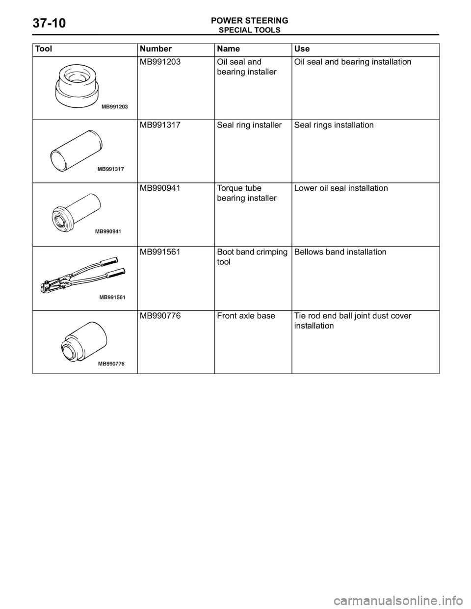
MB991203
SPECIA L T O OLS
POWER ST E E RING37-10
MB991203Oil seal an d
bearing in
st allerOil seal and bea ring inst allation
MB991317
MB991317Seal ring in st allerSeal rings inst a llat i on
MB990941
MB990941To rqu e tube
bearing in
st allerLower oil seal inst allation
MB991561
MB991561Boot ba nd crimp i n g
toolBellows ban d inst a lla tion
MB990776
MB990776Front ax le baseTi e rod end b a ll join t dust co ver
inst
a llat i on
Tool Num ber Na me Use
Page 241 of 800
ON-VEHICLE SERVICE
POWER STEERING37-11
ON-VEHICLE SERVICE
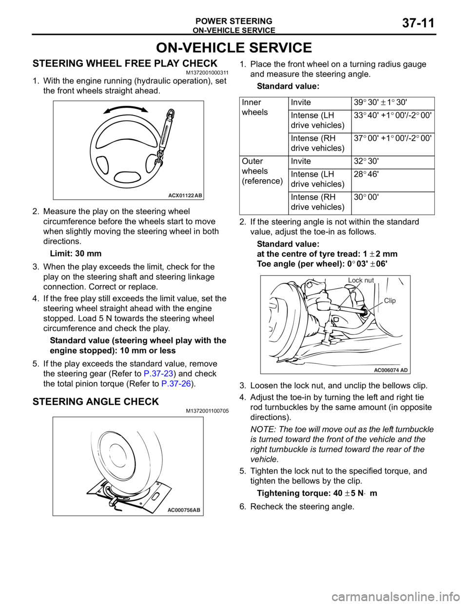
STEERING WHEEL FREE PLAY CHECKM1372001000311
1. With the engine running (hydraulic operation), set the front wheels straight ahead.
ACX01122 AB
2.Measure the play on th e ste e ring wh eel
circumfer ence before the whee ls st a r t to move
when slightly moving the stee ring whe e l in both
direct ions.
Limit: 30 mm
3.Wh en the play exceed s the limit, check fo r the
play on the stee ring shaf t and stee ring linkage
connectio n . Correct or replace .
4.If th e free play still exceeds the limit valu e, set t he
steering wheel stra ight ahead with the engine
stoppe d. Loa d 5 N towards the steer ing whee l
circumfer ence and check the play .
St andard value (steering whee l pla y with the
engine s
t opped): 1 0 mm o r l ess
5.If the play e xce eds the st an dard value , remove
th e ste e ring gear (Refe r to
P.37-23) and check
the tot a l p i nion torqu e (Refer to P.37-26).
STEERING ANGLE CHECKM137200 1 1 0070 5
AC000756AB
1.Place t he fron t wh eel on a tu rning radiu s gau ge
a nd me asure the steering ang le.
St andard va lue:
Inner
wheelsInvite39°30' ± 1°30'
Intense (LH
drive vehicles)33°40' +1°00'/-2°00'
Intense (RH
drive vehicles)37°00' +1°00'/-2°00'
Outer
wheels
(reference)Invite32°30'
Intense (LH
drive vehicles)28°46'
Intense (RH
drive vehicles)30°00'
2.If the steerin g ang le is not within the st a ndard
value , adjust t he toe-in as follows.
St andard va lue:
at the centre of tyre trea d: 1 ± 2 mm
To e angle (p er whee l): 0°03' ± 06'
AC006074 AD
Lock nut
Clip
3.L oose n the lock nut, and un clip the bellows clip .
4.Adjust the toe - in by turning th e lef t an d righ t tie
ro d turnb u ckles by th e sa me a m oun t (in o pposite
directions).
NOTE: The to e will move out as th e lef t turnbuckle
is tur
ned toward the fro n t of th e ve hicle an d the
right tu
rnbuckle is turned toward the rear of the
vehicle.
5. T i ghten the lo ck nut to the specified torque , and
tighten the be llo ws by the clip .
Ti ghte n ing torque: 40 ± 5 N⋅m
6.Recheck the stee ring a ngle .
Page 244 of 800
ON-VEHICLE SERVICE
POWER STEERING37-14
POWER STEERING SYSTEM AIR
BLEEDING
M1372002200330
Perform air bleeding procedure as necessary after
replacing the steering gear or the steering fluid lines.
1. Raise and support the front wheels.
2. Disconnect the ignition coil connectors (Refer to GROUP 16, Ignition Coil
P.16-38 or P.16-39).
CAUTION
Perform air bleeding only while cranking the
engine. If air bleeding is performed while the
engine is running, air could enter the fluid. Dur
-
ing air bleeding, refill the steering fluid supply so
that the level never falls below the "MIN" mark on
the oil reservoir.
3. Turn the steering wheel all the way to the left and
right five or six times wh ile using the starter motor
to crank the engine intermittently several times
(for 15 to 20 seconds).
4. Connect the ignition coil connectors (Refer to GROUP 16, Ignition Coil
P.16-38 or P.16-39).
5. Start the engine (idling).
6. Turn the steering wheel to the left and right until there are no air bubbles in the oil reservoir.
7. Confirm that the fluid is not milky, and that the level is between "MAX" and "MIN" marks.
8. Confirm that there is very little change in the fluid
level when the steering wheel is turned left and
right.
CAUTION
If the fluid level rises suddenly after the engine is
stopped, the air has not been completely bled. If
air bleeding is not complete, there will be abnor
-
mal noises from the pump and the flow-control
valve, and this condition could cause reduce the
life of the power steering components.
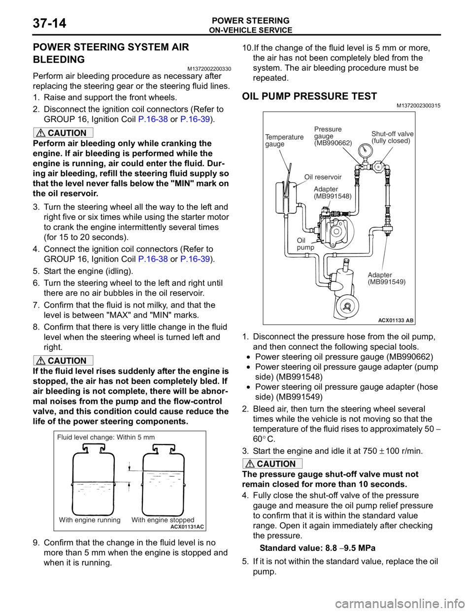
ACX01131With engine running With engine stoppedAC
Fluid level change: Within 5 mm
9. Confirm that the change in the fluid level is no more than 5 mm when the engine is stopped and
when it is running.
10.If the change of the fluid level is 5 mm or more,
the air has not been completely bled from the
system. The air bleeding procedure must be
repeated.
OIL PUMP PRESSURE TEST
M1372002300315
ACX01133
Temperature
gauge
Oil reservoir
Adapter
(MB991548)
Oil
pump Adapter
(MB991549)
AB
Shut-off valve
(fully closed)
Pressure
gauge
(MB990662)
1. Disconnect the pressure hose from the oil pump,
and then connect the following special tools.
•Power steering oil pressure gauge (MB990662)
•Power steering oil pressure gauge adapter (pump
side) (MB991548)
•Power steering oil pressure gauge adapter (hose
side) (MB991549)
2. Bleed air, then turn the steering wheel several times while the vehicle is not moving so that the
temperature of the fluid rises to approximately 50
−
60
°C.
3. Start the engine and idle it at 750 ± 100 r/min.
CAUTION
The pressure gauge shut-off valve must not
remain closed for more than 10 seconds.
4. Fully close the shut-off valve of the pressure gauge and measure the oil pump relief pressure
to confirm that it is within the standard value
range. Open it again immediately after checking
the pressure.
Standard value: 8.8 − 9.5 MPa
5. If it is not within the standard value, replace the oil pump.
Page 253 of 800
POWER STEERING GEAR BOX AND LINKAGE
POWER STEERING37-23
POWER STEERING GEAR BOX AND LINKAGE
REMOVAL AND INSTALLATIONM1372010900237
WARNING
Before removing the steering gear, refer to GROUP 52B, Service Precautions (P.52B-5) and
Air Bag Module and Clock Spring (P.52B-194). Centre the front wheels. Failure to do so may
damage the SRS clock spring and render the SRS system inoperative, risking serious injury.
Pre-removal Operation
•Power Steering Fluid Draining (Refer to P.37-13.)
Post-installation Operation
•Check the dust cover for cracks or damage by pushing it
with your finger.
•Power Steering Fluid Supplying (Refer to P.37-13.)
•Power Steering Fluid Line Bleeding (Refer to P.37-14.)
•Checking Steering Wheel Position with Wheels Straight
Ahead.
•Front Wheel Alignment Adjustment (Refer to GROUP 33,
On-vehicle Service
− Front Wheel Alignment Check and
Adjustment
P.33-6.)
AC304920 AB
57 ± 7 N·m
15 ± 3 N·m
70 ± 10 N·m
7
3
8
5
6
9
10 24
1
12 ± 2 N·m
12 ± 2 N·m
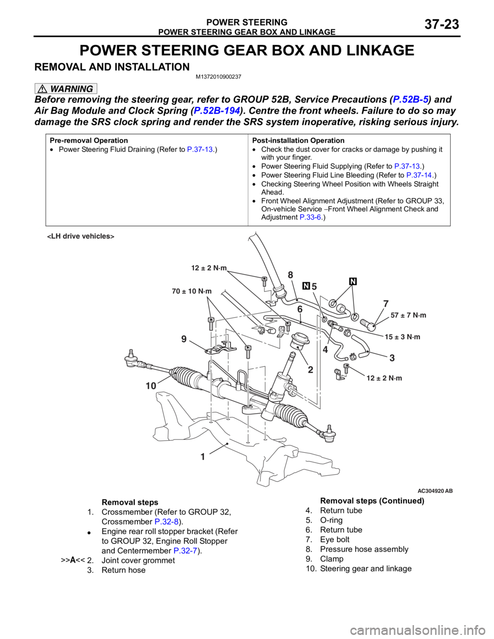
Removal steps
1.Crossmember (Refer to GROUP 32,
Crossmember
P.32-8).
•Engine rear roll stopper bracket (Refer
to GROUP 32, Engine Roll Stopper
and Centermember
P.32-7).
>>A<<2.Joint cover grommet
3.Return hose
4.Return tube
5.O-ring
6.Return tube
7.Eye bolt
8.Pressure hose assembly
9.Clamp
10.Steering gear and linkage
Removal steps (Continued)
Page 270 of 800
POWER STEERING HOSES
POWER STEERING37-40
POWER STEERING HOSES
REMOVAL AND INSTALLATIONM1372005700679
CAUTION
•Before removing the clock spring, refer to GROUP 52B, Service Precautions (P.52B-5) and Air Bag
Module and Clock Spring (P.52B-194). Also, put the front wheels in straight-ahead position. Fail-
ure to do so may damage the SRS clock spring and render the SRS air bag inoperative, which
results serious driver injury.
•
Pre-removal and Post-installation Operation
•Power Steering Fluid Draining and Refilling (Refer to P.37-13). and Bleeding (Refer to P.37-14).
*: Indicates parts which should be initially tightened, and then fully tightened after placing the
vehicle horizontally and loading the full weight of the engine on the vehicle body.
AC304699AB
15 ± 3 N·m
18 ± 2 N·m
167 ± 9 N·m
12 ± 2 N·m
49 ± 10 N·m
12 ± 2 N·m
57 ± 7 N·m*57 ± 7 N·m
3
1
2
9
1310
7 11
12
5 68
12 ± 2 N·m
12 ± 2 N·m
2
9
4
7
8
7
8
7
8
57 ± 7 N·m57 ± 7 N·m
57 ± 7 N·m
12 ± 2 N·m
167 ± 9 N·mCrossmember
12 ± 2 N·m
<1300, 1600>
<2000>
12 ± 2 N·m
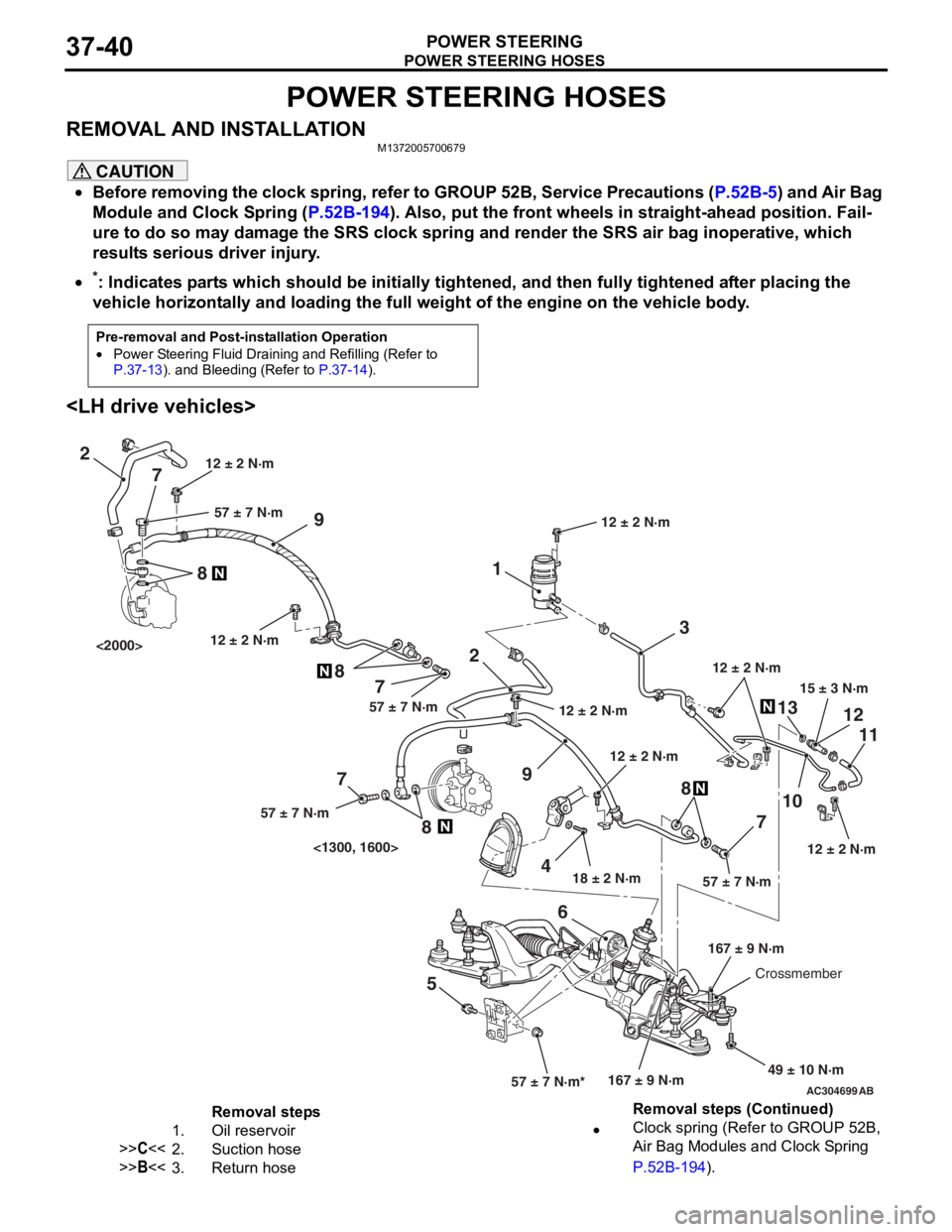
Removal steps
1.Oil reservoir
>>C<<2.Suction hose
>>B<<3.Return hose
•Clock spring (Refer to GROUP 52B,
Air Bag Modules and Clock Spring
P.52B-194).
Removal steps (Continued)
Page 271 of 800
POWER STEERING HOSES
POWER STEERING37-41
AC304698AB
15 ± 3 N·m18 ± 2 N·m
167 ± 9 N·m
12 ± 2 N·m
49 ± 10 N·m
12 ± 2 N·m
57 ± 7 N·m*
3
1
2 9
10
7
5
6
2 4
8 857 ± 7 N·m
167 ± 9 N·m
Crossmember 12 ± 2 N·m
<1300, 1600>
<2000>
7
6
57 ± 7 N·m
7
6
57 ± 7 N·m
7
6
57 ± 7 N·m
12 ± 2 N·m
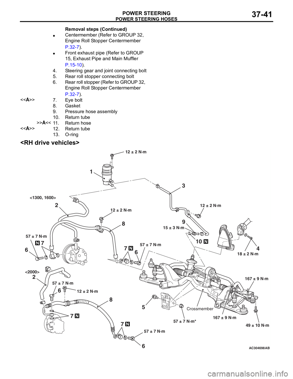
•Centerme mbe r (Refe r to GROUP 3 2 ,
En
gin e Ro ll S t op pe r Ce nt er m e m b er
P.32-7).
•Front exha ust pi pe (Re f e r to GROUP
15
, Exhau st Pipe a nd Ma in Muf f ler
P.15-10).
4.St e e r i ng gea r a nd jo int co nn ectin g b o lt
5.Rear ro ll stopp er con n e c ting b o lt
6.Rear r o ll s t op pe r (Re f er t o GRO U P 32 ,
En
gin e Ro ll S t op pe r Ce nt er m e m b er
P.32-7).
<>7.Eye bolt
8.Gask et
9.Pressure hose ass e mbly
10.Return tu be
>>A<<11.Return hose
<>12.Return t u be
13.O-rin g
Remo va l st ep s ( C o n t i n u e d )
Page 272 of 800
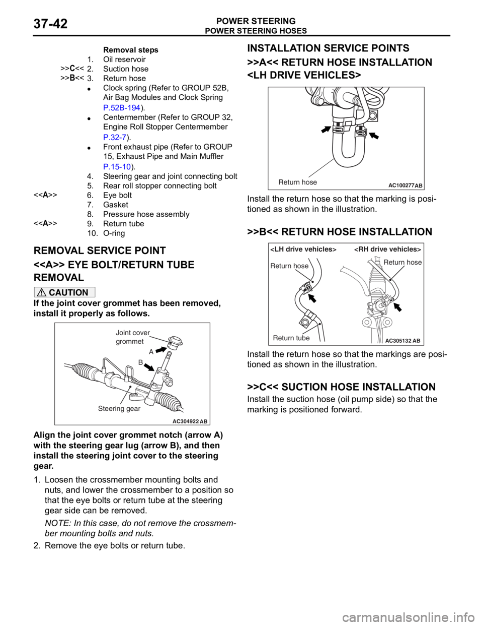
Removal steps
1.Oil reservoir
>>C<<2.Suction hose
>>B<<3.Return hose
•Clock spring (Refer to GROUP 52B,
Air Bag Modules and Clock Spring
P.52B-194).
•Centermember (Refer to GROUP 32,
Engine Roll Stopper Centermember
P.32-7).
•Front exhaust pipe (Refer to GROUP
15, Exhaust Pipe and Main Muffler
P.15-10).
4.Steering gear and joint connecting bolt
5.Rear roll stopper connecting bolt
<>6.Eye bolt
7.Gasket
8.Pressure hose assembly
<>9.Return tube
10.O-ring
POWE R STEERING HOSES
POWER S T E E RING37-42
REMOVA L SER V ICE POINT
<> EYE BOLT /RETURN TUBE
REMOV
A L
CAUTION
If the joint cover grommet has been removed,
install it properly as follows.
AC304922AB
A
B
Joint cover
grommet
Steering gear
Align the joint cover grommet notch (arrow A)
with the steering gear lug (arrow B), and then
install the steering joint cover to the steering
gear.
1. Loosen the crossmember mounting bolts and nuts, and lower the crossmember to a position so
that the eye bolts or return tube at the steering
gear side can be removed.
NOTE: In this case, do not remove the crossmem-
ber mounting bolts and nuts.
2. Remove the eye bolts or return tube.
INSTALLATION SERVICE POINTS
>>A<< RETURN HOSE INSTALLATION
AC100277 ABReturn hose
Install the return hose so that the marking is posi-
tioned as shown in the illustration.
>>B<< RETURN HOSE INSTALLATION
AC305132AB
Return hose
Return tubeReturn hose
Install the return hose so that the markings are posi-
tioned as shown in the illustration.
>>C<< SUCTION HOSE INSTALLATION
Install the suction hose (oil pump side) so that the
marking is positioned forward.
Page 278 of 800
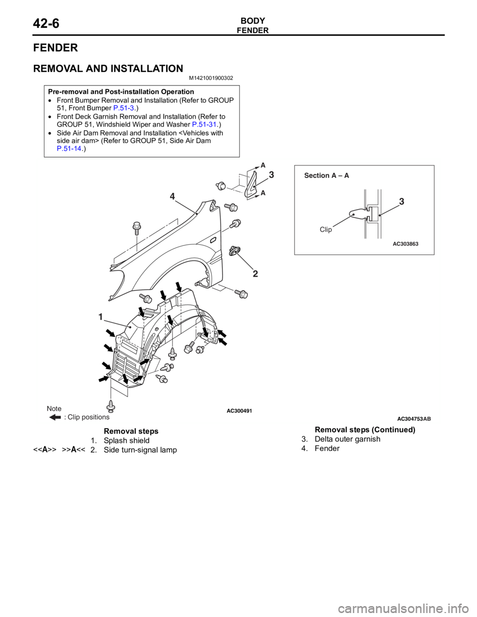
FENDER
BODY42-6
FENDER
REMOVAL AND INSTALLATION
M1421001900302
Pre-removal and Post-installation Operation
•Front Bumper Removal and Installation (Refer to GROUP
51, Front Bumper P.51-3.)
•Front Deck Garnish Removal and Installation (Refer to
GROUP 51, Windshield Wiper and Washer P.51-31.)
•Side Air Dam Removal and Installation
P.51-14.)
AC300491AC304753
AC303863
Clip
Section A – A
AB
A A
1
23
3
4
Note
: Clip positions
Removal steps
1.Splash shield
<>>>A<<2.Side turn-signal lamp
3.Delta outer garnish
4.Fender
Removal steps (Continued)
Page 279 of 800
