Front shock MITSUBISHI LANCER 2006 Workshop Manual
[x] Cancel search | Manufacturer: MITSUBISHI, Model Year: 2006, Model line: LANCER, Model: MITSUBISHI LANCER 2006Pages: 800, PDF Size: 45.03 MB
Page 166 of 800
TROUBLESHOOTING
WHEEL AND TYRE31-4
WHEEL BALANCE ACCURACY
M1311001700247
PURPOSE
This section contains tips and procedures for achiev-
ing accurate wheel balance. Steering wheel vibration
and/or body shake can result if any of these proce
-
dures are not carefully observed.
1. Wheels and tyres must be properly mounted on a balancer in order to achieve correct balance.
Centring the wheel on the shaft of the balancer is
essential for proper mounting.
2. Off-the-car wheel balancers must be calibrated periodically to ensure good balancing results. An
inaccurately calibrated balancer could cause
unnecessary replacement of tyres, shocks,
suspension components, or steering components.
Check your balancer's calibration approximately
every 100 balances. Your wheel balancer's instruc
-
tion manual should include calibration procedures. If
the calibration procedures specifically for your bal
-
ancer are missing, use the generic steps in this sec-
tion for zero calibration, static balance, and dynamic
balance checks. The wheel balancer calibration
checks are also described in the flowchart. (Refer to
P.31-6).
PROCEDURE
1. Confirm that the balancer's cone and the wheel
mounting cone are undamaged and free of dirt
and rust.
2. On this vehicle, the wheel's centre hole on the hub side has a chamfered edge. Use a
back-mounting cone on your wheel balancer to
centre the wheel on the balancer shaft.
3. Install a wheel mounting cone. The appropriate size cone for this vehicle is 67.0 mm.
4. Before balancing the wheel, remove any wheel weights from both sides. Also check both sides for
any damage.
5. When installing wheel weights, hammer them at a straight (not diagonal) angle.
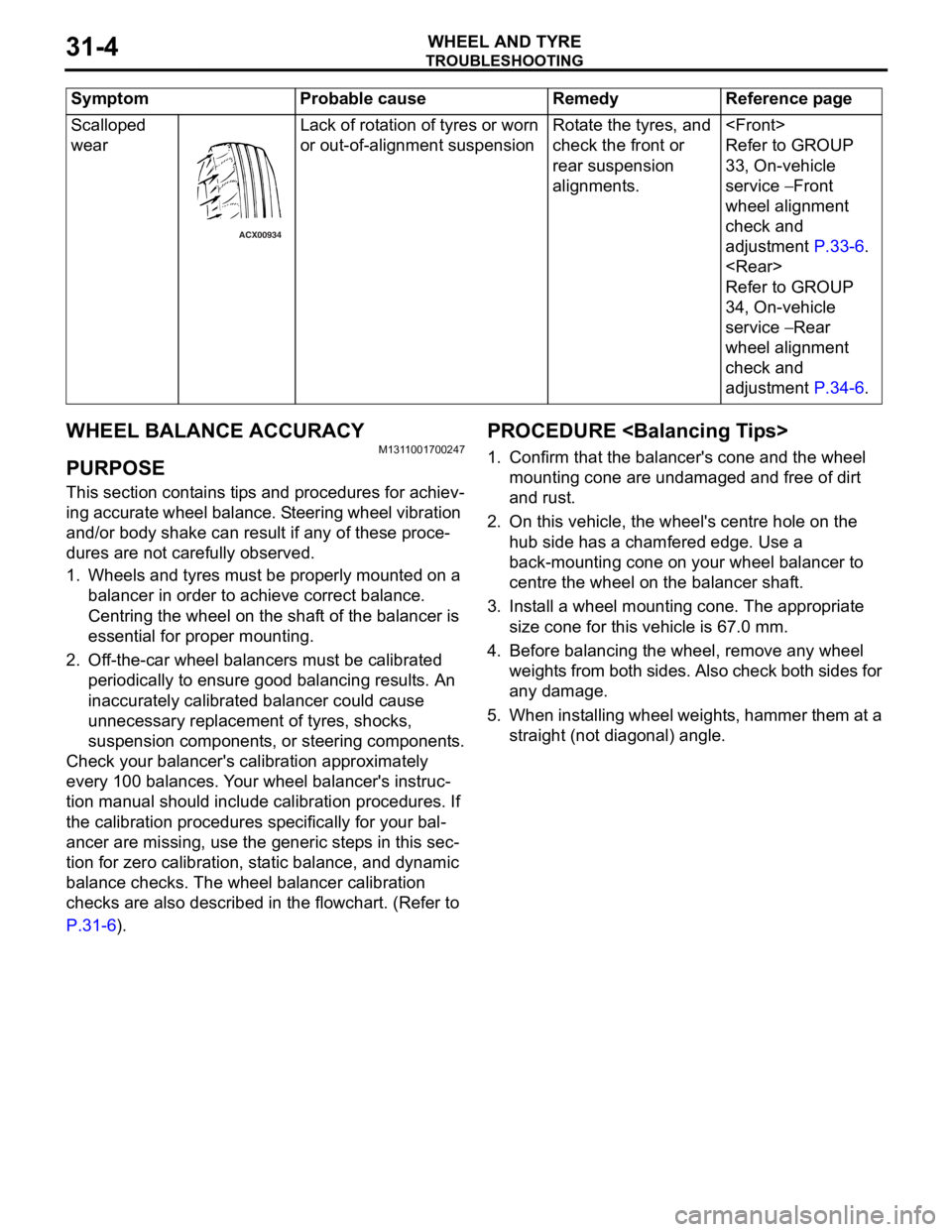
Scalloped
wear
ACX00934
Lack of rot a tio n of tyres or worn
or out-of-a
lign m ent suspensionRota te th e tyre s, an d
check the f
r ont or
rea
r suspension
alignment
s.
Refer to GROUP
33
, On -vehicle
serv
ic e
− Front
whee
l alignment
check and
ad
justmen t
P.33-6.
Refer to GROUP
34
, On -vehicle
serv
ic e
− Rear
whee
l alignment
check and
ad
justmen t
P.34-6.
Sy mptom P robable cause Reme dy Referen ce p a g e
Page 184 of 800
GENERAL INFORMATION
FRONT SUSPENSION33-2
GENERAL INFORMATION
M1332000100537
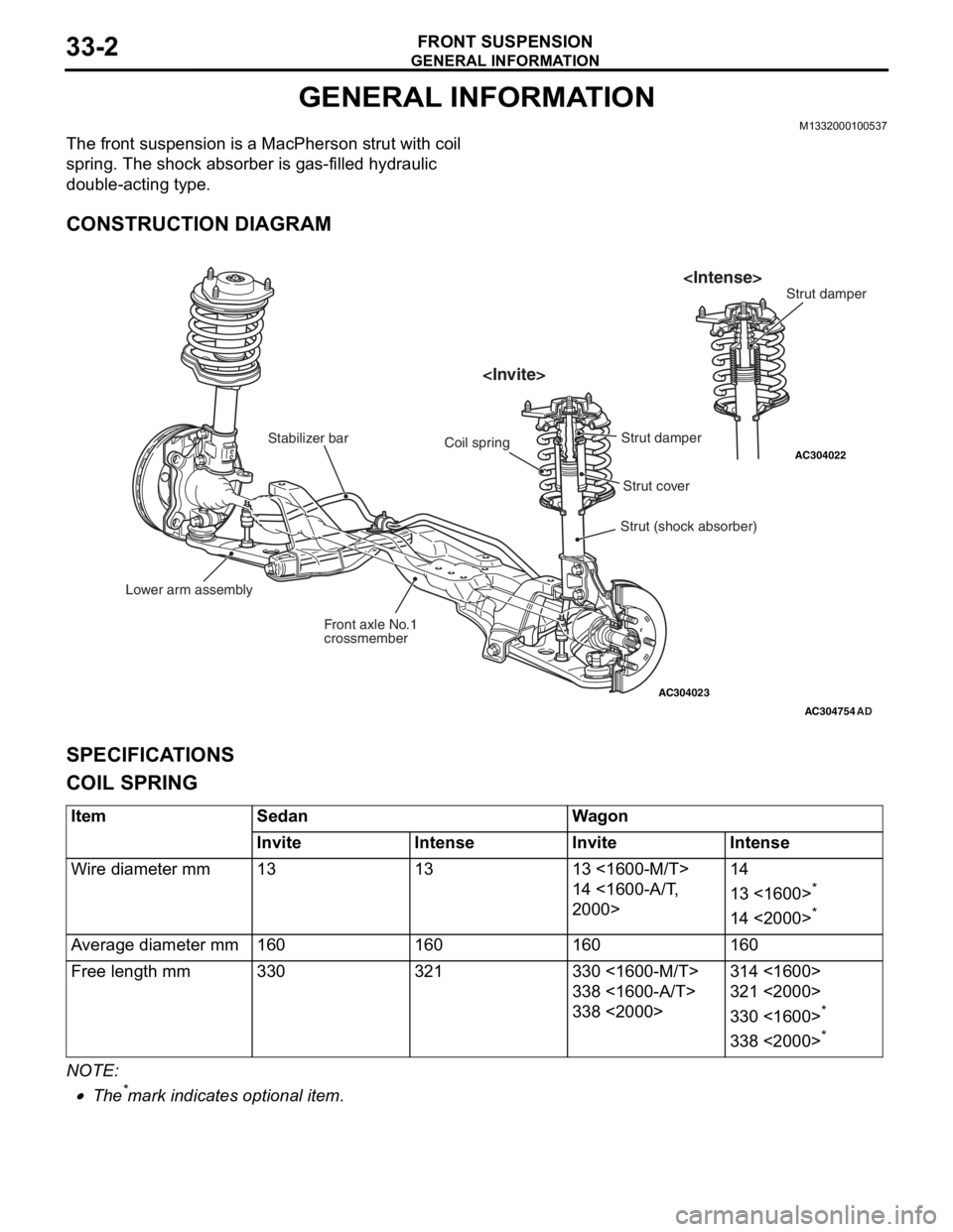
The front suspension is a MacPherson strut with coil
spring. The shock absorber is gas-filled hydraulic
double-acting type.
CONSTRUCTION DIAGRAM
AC304023
AC304022
AC304754
Lower arm assembly Front axle No.1
crossmember
Stabilizer bar
Strut (shock absorber)
Coil spring
AD
Strut cover
Strut damper
SPECIFICA
T IONS
COIL SPRING
ItemSedanWagon
InviteIntenseInviteIntense
Wire diameter mm131313 <1600-M/T>
14 <1600-A/T,
2000>
14
13 <1600>*
14 <2000>*
Average diameter mm160160160160
Free length mm330321330 <1600-M/T>
338 <1600-A/T>
338 <2000>
314 <1600>
321 <2000>
330 <1600>*
338 <2000>*
NOTE: .
•The*mark indicat e s op tiona l it em.
Page 205 of 800
ON-VEHICLE SERVICE
REAR SUSPENSION34-7
Carry out adjustment by turning the toe adjusting bolt
(control link mounting bolt which is located on the
inner side of the body).
NOTE: .
•LH: Clockwise viewed from the front → To e - i n
•RH: Clockwise viewed from the front → Toe-out
•Turning the toe adjusting bolt by one groove of
the scale, toe can be changed approximately 2.6
mm (single side toe angle equivalent to 16').
CONTROL LINK PILLOW BALL BUSHING
AXIAL PLAY CHECK
M1341018500066
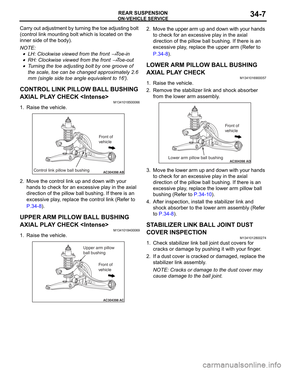
1. Raise the vehicle.
AC304398ABControl link pillow ball bushing
Front of
vehicle
2.Move the control link up and d o wn with your
ha nds to ch eck for an excessive pla y in the a x ia l
direct ion o f the p illow ball bushing . If the r e is an
exce ssive play , re place the cont rol link (Re f er to
P.34-8).
UPPER ARM PILLOW BALL BUSHING
AXIAL PLAY CHECK
M13410184 0006 9
1.Raise th e ve hicle.
AC304398AC
Upper arm pillow
ball bushing
Front of
vehicle
2. Move the up per arm up and down with you r hand s
to che ck for an e xce ssive play in the axial
d i rection o f the p illow ball bushing . If the r e is an
e xce ssive play , re place the upper arm (Refe r to
P.34-8).
LOWER ARM PILLOW BALL BUSHING
AXIAL PLAY CHECK
M13410169 0005 7
1.Raise th e ve hicle.
2.Remove the st a b ilizer link and shock a b sorb er
f r om t h e l o we r arm a s s e mb l y .
AC304398ADLower arm pillow ball bushing
Front of
vehicle
3.Move the lower a r m u p and down with your h ands
to che ck for an e xce ssive play in the axial
d i rection o f the p illow ball bushing . If the r e is an
e xce ssive play , re place the lower a r m pillo w b a ll
b u shing (Refer to
P.34-10).
4.Af ter inspe c tio n , in st all the st a b ilizer link and
shock a b sorb er to the lower arm assembly (Refer
to
P.34-8).
STABILIZER LINK BALL JOINT DUST
COVER INSPECTION
M1341 0128 0027 4
1.Check st abilize r lin k ba ll joint dust covers f o r
cracks o r damage by pushing it wit h you r fing er .
2. If a du st cove r is crack ed or da mag ed, rep l ace t he
st a b ili zer link assembly .
NOTE: Cracks or dama ge to t he dust co ver may
cause damage to the b a ll join t.
Page 231 of 800
37-1
GROUP 37
POWER STEERING
CONTENTS
GENERAL INFORMATION . . . . . . . .37-3
SERVICE SPECIFICATIONS . . . . . . .37-6
LUBRICANTS . . . . . . . . . . . . . . . . . .37-7
SEALANTS . . . . . . . . . . . . . . . . . . . .37-7
SPECIAL TOOLS . . . . . . . . . . . . . . . .37-8
ON-VEHICLE SERVICE . . . . . . . . . . .37-11
STEERING WHEEL FREE PLAY CHECK . 37-11
STEERING ANGLE CHECK . . . . . . . . . . . . 37-11
TIE ROD END BALL JOINT TURNING
TORQUE CHECK . . . . . . . . . . . . . . . . . . . . 37-12
STATIONARY STEERING EFFORT
CHECK . . . . . . . . . . . . . . . . . . . . . . . . . . . . 37-12
STEERING WHEEL RETURN TO
CENTRE CHECK . . . . . . . . . . . . . . . . . . . . 37-13
DRIVE BELT TENSION CHECK. . . . . . . . . 37-13
FLUID LEVEL CHECK . . . . . . . . . . . . . . . . 37-13
FLUID REPLACEMENT . . . . . . . . . . . . . . . 37-13
POWER STEERING SYSTEM AIR
BLEEDING . . . . . . . . . . . . . . . . . . . . . . . . . 37-14
OIL PUMP PRESSURE TEST . . . . . . . . . . 37-14
POWER STEERING PRESSURE
SWITCH CHECK . . . . . . . . . . . . . . . . . . . . . 37-15
TIE ROD END BALL JOINT DUST
COVER CHECK . . . . . . . . . . . . . . . . . . . . . 37-15
STEERING COLUMN SHAFT ASSEMBLY
SHOCK ABSORBING MECHANISM
CHECK . . . . . . . . . . . . . . . . . . . . . . . . . . . . 37-15
STEERING WHEEL . . . . . . . . . . . . . .37-17
REMOVAL AND INSTALLATION
REMOVAL AND INSTALLATION
Continued on next page
WARNINGS REGARDING SERVICING OF SUPPLEMENTAL RESTRAINT SYSTEM (SRS) EQUIPPED VEHICLES
WARNING
•Improper service or maintenance of any component of the SRS, or any SRS-related component, can lead to
personal injury or death to service personnel (from inad vertent firing of the air bag) or to the driver and
paassenger (from renderin g the SRS inoperative).
•Service or maintenance of any SRS component or SRS-related component must be performed only at an
authorized MITSUBISHI dealer.
•MITSUBISHI dealer personnel must thoroughly review th is manual, and especially its GROUP 52B - Supplemental
Restraint System (SRS) before begi nning any service or maintenance of any component of the SRS or any
SRS-related component.
NOTE
The SRS includes the following components: SRS air bag control unit, SRS warning light, front impact sensors, air bag module,
clock spring, and interconnecting wiring. Other SRS-related components (that may have to be removed/installed in connection
with SRS service or maintenance) are indicated in the table of contents by an asterisk (*).