Special tool MITSUBISHI LANCER 2006 Workshop Manual
[x] Cancel search | Manufacturer: MITSUBISHI, Model Year: 2006, Model line: LANCER, Model: MITSUBISHI LANCER 2006Pages: 800, PDF Size: 45.03 MB
Page 7 of 800
12-1
GROUP 12
ENGINE
LUBRIC ATION
CONTENTS
GENERAL INFORMATIO N . . . . . . . .12-2
SERVICE SPECIFICATION . . . . . . . .12-2
LUBRICANT . . . . . . . . . . . . . . . . . . . .12-2
SEALANT . . . . . . . . . . . . . . . . . . . . . .12-3
SPECIAL TOOLS . . . . . . . . . . . . . . . .12-3
ON-VEHICLE SERVICE . . . . . . . . . . .12-4
ENGINE OIL CHECK . . . . . . . . . . . . . . . . . 12-4
ENGINE OIL REPLACEMENT . . . . . . . . . . 12-4
ENGINE OIL FILTER REPLACEMENT . . . . 12-4
OIL PRESSURE CHECK . . . . . . . . . . . . . . 12-5
Page 9 of 800
SEALANT
ENGINE LUBRICATION12-3
SEALANT
M1121000500258
ItemSpecified sealantRemark
Oil pressure switch3M ATD Part No. 8660 or equivalentSemi-drying sealant
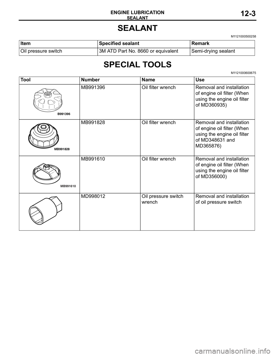
SPECIAL TOOLS
M1121000600675
ToolNumberNameUse
B991396
MB991396Oil filter wrenchRemoval and inst allation
of e
ngin e oil filter (Whe n
using
the eng ine o il f ilte r
of MD36093
5)
MB991828
MB991828Oil filter wrenchRemoval and inst allation
of e
ngin e oil filter (Whe n
using
the eng ine o il f ilte r
of MD34863
1 and
MD3
65876)
MB991610
MB991 610Oil filter wrenchRemoval and inst allation
of e
ngin e oil filter (Whe n
using
the eng ine o il f ilte r
of MD35600
0)
MD998012Oil pres su re swit ch
wrenchRemoval and inst allation
of o
il p r essure switch
Page 11 of 800
ON-VEHICLE SERVICE
ENGINE LUBRICATION12-5
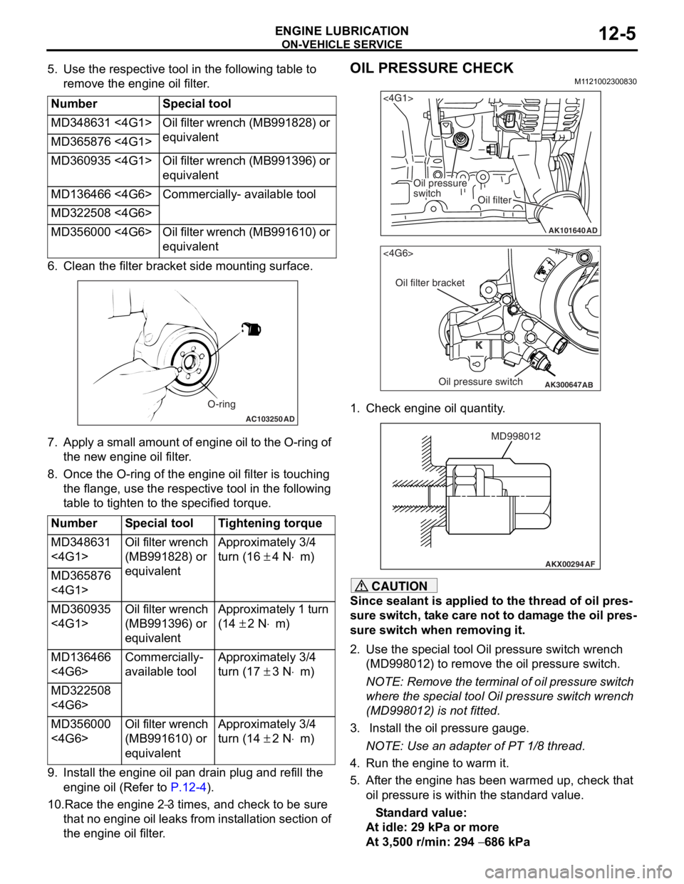
5. Use the respective tool in the following table to remove the engine oil filter.
NumberSpecial tool
MD348631 <4G1>Oil filter wrench (MB991828) or
equivalent
MD365876 <4G1>
MD360935 <4G1>Oil filter wrench (MB991396) or
equivalent
MD136466 <4G6>Commercially- available tool
MD322508 <4G6>
MD356000 <4G6>Oil filter wrench (MB991610) or
equivalent
6. Cle an the filt er bracket side mou n ting surfa c e.
AC103250AD
O-ring
7.Ap ply a small a m ou nt o f en gine o i l to th e O-rin g of
th e new eng ine oil f ilte r .
8.Once the O-ring of the engine oil filter is tou c hing
th e flange, use the resp ective tool in the following
t able to tighten to the specified tor que.
NumberSpecial toolTightening torque
MD348631
<4G1>Oil filter wrench
(MB991828) or
equivalentApproximately 3/4
turn (16
± 4 N⋅m)
MD365876
<4G1>
MD360935
<4G1>Oil filter wrench
(MB991396) or
equivalentApproximately 1 turn
(14
± 2 N⋅m)
MD136466
<4G6>Commercially-
available toolApproximately 3/4
turn (17
± 3 N⋅m)
MD322508
<4G6>
MD356000
<4G6>Oil filter wrench
(MB991610) or
equivalentApproximately 3/4
turn (14
± 2 N⋅m)
9.In st all the en gine oil p a n drain plu g and refill the
en gine oil (Re f er to
P.12-4).
10.Race the en gine 2−3 times, and che ck to be sure
th
at n
o
en
gin
e
oil leaks fr om in st allation sectio n of
th
e engine oil filter
.
OIL PRESSURE CHECK
M1 121 0023 0083 0
AK101640
<4G1>
Oil pressure
switch
Oil filter
AD
AK300647
AB
<4G6>
Oil filter bracket
Oil pressure switch
1.Check e ngin e oil quan tity .
AKX00294
MD998012
AF
CAUTION
Since sealant is applied to the thread of oil pres-
sure switch, take care not to damage the oil pres-
sure switch when removing it.
2. Use the special tool Oil pressure switch wrench
(MD998012) to remove the oil pressure switch.
NOTE: Remove the terminal of oil pressure switch
where the special tool Oil pressure switch wrench
(MD998012) is not fitted.
3. Install the oil pressure gauge.
NOTE: Use an adapter of PT 1/8 thread.
4. Run the engine to warm it.
5. After the engine has been warmed up, check that oil pressure is within the standard value.
Standard value:
At idle: 29 kPa or more
At 3,500 r/min: 294 − 686 kPa
Page 12 of 800
ON-VEHICLE SERVICE
ENGINE LUBRICATION12-6
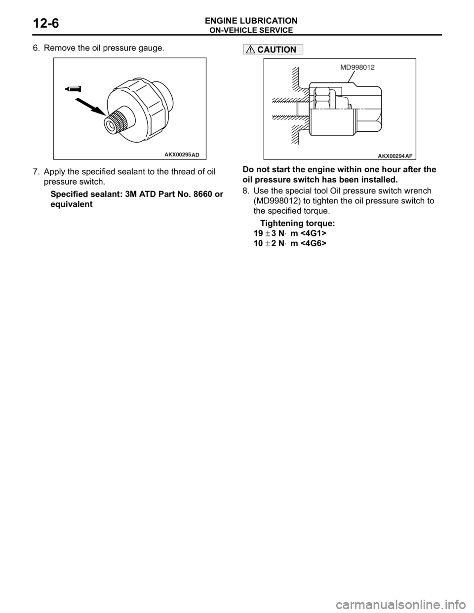
6. Remove the oil pressure gauge.
AKX00295AD
7.App l y t he sp ecified sealant to the thr ead of oil
pres sure sw itc h .
Specified sealan t: 3M A T D Part No. 8660 or
equival
ent
AKX00294
MD998012
AF
CAUTION
Do not start the engine within one hour after the
oil pressure switch has been installed.
8. Use the special tool Oil pressure switch wrench (MD998012) to tighten the oil pressure switch to
the specified torque.
Tightening torque:
19 ± 3 N⋅m <4G1>
10 ± 2 N⋅m <4G6>
Page 15 of 800
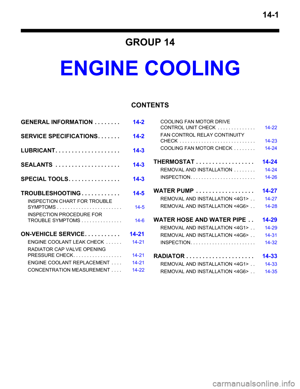
14-1
GROUP 14
ENGINE COOLING
CONTENTS
GENERAL INFORMATION . . . . . . . .14-2
SERVICE SPECIFICATIONS . . . . . . .14-2
LUBRICANT . . . . . . . . . . . . . . . . . . . .14-3
SEALANTS . . . . . . . . . . . . . . . . . . . .14-3
SPECIAL TOOLS . . . . . . . . . . . . . . . .14-3
TROUBLESHOOTING . . . . . . . . . . . .14-5
INSPECTION CHART FOR TROUBLE
SYMPTOMS . . . . . . . . . . . . . . . . . . . . . . . . 14-5
INSPECTION PROCEDURE FOR
TROUBLE SYMPTOMS . . . . . . . . . . . . . . . 14-6
ON-VEHICLE SERVICE . . . . . . . . . . .14-21
ENGINE COOLANT LEAK CHECK . . . . . . 14-21
RADIATOR CAP VALVE OPENING
PRESSURE CHECK . . . . . . . . . . . . . . . . . . 14-21
ENGINE COOLANT REPLACEMENT . . . . 14-21
CONCENTRATION MEASUREMENT . . . . 14-22
COOLING FAN MOTOR DRIVE
CONTROL UNIT CHECK . . . . . . . . . . . . . . 14-22
FAN CONTROL RELAY CONTINUITY
CHECK . . . . . . . . . . . . . . . . . . . . . . . . . . . . 14-23
COOLING FAN MOTOR CHECK . . . . . . . . 14-24
THERMOSTAT . . . . . . . . . . . . . . . . . .14-24
REMOVAL AND INSTALLATION . . . . . . . . 14-24
INSPECTION. . . . . . . . . . . . . . . . . . . . . . . . 14-26
WATER PUMP . . . . . . . . . . . . . . . . . .14-27
REMOVAL AND INSTALLATION <4G1> . . 14-27
REMOVAL AND INSTALLATION <4G6> . . 14-28
WATER HOSE AND WATER PIPE . .14-29
REMOVAL AND INSTALLATION <4G1> . . 14-29
REMOVAL AND INSTALLATION <4G6> . . 14-31
INSPECTION. . . . . . . . . . . . . . . . . . . . . . . . 14-32
RADIATOR . . . . . . . . . . . . . . . . . . . . .14-33
REMOVAL AND INSTALLATION <4G1> . . 14-33
REMOVAL AND INSTALLATION <4G6> . . 14-35
Page 17 of 800
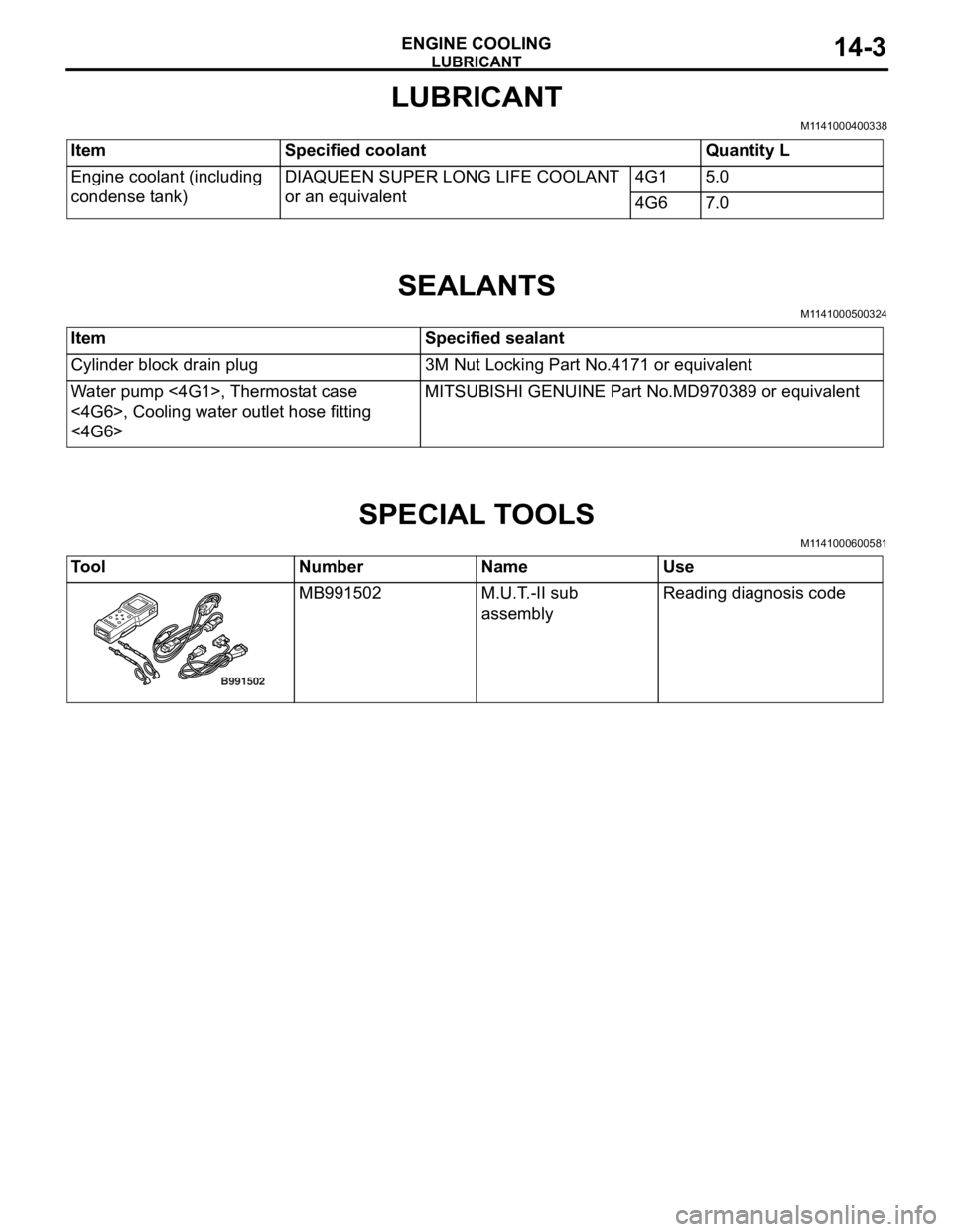
LUBRICANT
ENGINE COOLING14-3
LUBRICANT
M1141000400338
ItemSpecified coolantQuantity L
Engine coolant (including
condense tank)DIAQUEEN SUPER LONG LIFE COOLANT
or an equivalent4G15.0
4G67.0
SEALANTS
M1141000500324
ItemSpecified sealant
Cylinder block drain plug3M Nut Locking Part No.4171 or equivalent
Water pump <4G1>, Thermostat case
<4G6>, Cooling water outlet hose fitting
<4G6>MITSUBISHI GENUINE Part No.MD970389 or equivalent
SPECIAL TOOLS
M1141000600581
ToolNumberNameUse
B991502
MB991502M.U.T. -II sub
assemblyReading diagno sis co de
Page 36 of 800
AC200625
Cylinder block
drain plug
AC
ON-VEHICLE SER VICE
ENGINE COOLING14-22
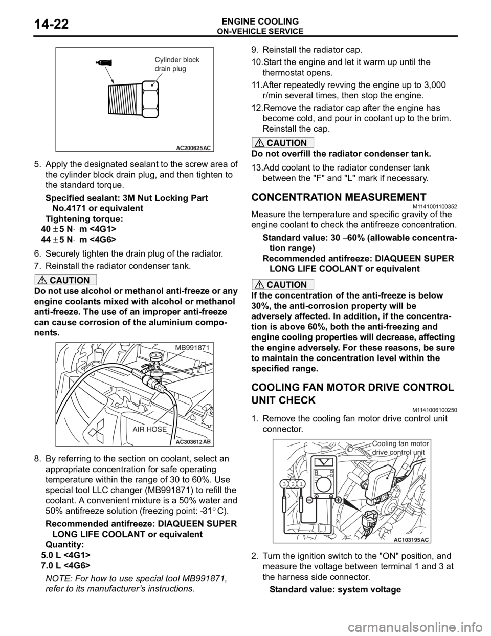
5.App l y the designa ted sealant to t he scre w area of
th e cylin der block drain plu g , and then tighten to
th e st and ard torq ue.
Sp e c ified s ealant: 3 M Nut Loc king Part
No. 4171 o r e quivale n t
Ti ghtenin g torque:
40 ± 5 N⋅m <4G1>
44 ± 5 N⋅m <4G6>
6.Securely tighten t he drain plug of t he radiator .
7.Reinst all the ra diato r con denser t ank.
CAUTION
Do not use alcohol or methanol anti-freeze or any
engine coolants mixed with alcohol or methanol
anti-freeze. The use of an improper anti-freeze
can cause corrosion of the aluminium compo
-
nents.
AC303612AB
MB991871
AIR HOSE
8. By referring to the section on coolant, select an
appropriate concentration for safe operating
temperature within the range of 30 to 60%. Use
special tool LLC changer (MB991871) to refill the
coolant. A convenient mixture is a 50% water and
50% antifreeze solution (freezing point:
−31°C).
Recommended antifreeze: DIAQUEEN SUPER LONG LIFE COOLANT or equivalent
Quantity:
5.0 L <4G1>
7.0 L <4G6>
NOTE: For how to use special tool MB991871,
refer to its manufacturer’s instructions.
9. Reinstall the radiator cap.
10.Start the engine and let it warm up until the thermostat opens.
11.After repeatedly revving the engine up to 3,000 r/min several times, then stop the engine.
12.Remove the radiator cap after the engine has become cold, and pour in coolant up to the brim.
Reinstall the cap.
CAUTION
Do not overfill the radiator condenser tank.
13.Add coolant to the radiator condenser tank between the "F" and "L" mark if necessary.
CONCENTRATION MEASUREMENT
M1141001100352
Measure the temperature and specific gravity of the
engine coolant to check the antifreeze concentration.
Standard value: 30 − 60% (allowable concentra-
tion range)
Recommended antifreeze: DIAQUEEN SUPER
LONG LIFE COOLANT or equivalent
CAUTION
If the concentration of the anti-freeze is below
30%, the anti-corrosion property will be
adversely affected. In addition, if the concentra
-
tion is above 60%, both the anti-freezing and
engine cooling properties will decrease, affecting
the engine adversely. For these reasons, be sure
to maintain the concentration level within the
specified range.
COOLING FAN MOTOR DRIVE CONTROL
UNIT CHECK
M1141006100250
1. Remove the cooling fan motor drive control unit connector.
AC103195
Y1716AU
1
23
AC
Cooling fan motor
drive control unit
2. Turn the ignition switch to the "ON" position, and
measure the voltage between terminal 1 and 3 at
the harness side connector.
Standard value: system voltage
Page 51 of 800
15-1
GROUP 15
INTAKE AND
EXHAUST
CONTENTS
GENERAL INFORMATIO N . . . . . . . .15-2
SERVICE SPECIFICATION . . . . . . . .15-2
SPECIAL TOOL . . . . . . . . . . . . . . . . .15-2
AIR CLEANER . . . . . . . . . . . . . . . . . .15-3
REMOVAL AND INSTALLATION . . . . . . . . 15-3
INLET MANIFOLD . . . . . . . . . . . . . . .15-5
REMOVAL AND INSTALLATION <4G1> . . 15-5
REMOVAL AND INSTALLATION <4G6> . . 15-6
INSPECTION. . . . . . . . . . . . . . . . . . . . . . . . 15-7
EXHAUST MANIFOLD . . . . . . . . . . . .15-7
REMOVAL AND INSTALLATION <4G1> . . 15-7
REMOVAL AND INSTALLATION <4G6> . . 15-9
INSPECTION. . . . . . . . . . . . . . . . . . . . . . . . 15-10
EXHAUST PIPE AND MAIN
MUFFLER . . . . . . . . . . . . . . . . . . . . . .15-10
REMOVAL AND INSTALLATION . . . . . . . . 15-10
Page 52 of 800
GENERAL INFORMATION
INTAKE AND EXHAUST15-2
GENERAL INFORMATION
M1151000100402
The exhaust pipe is divided into three parts.
SERVICE SPECIFICATION
M1151000300428
ItemStandard valueLimit
Manifold distortion of the installation surface mm0.15 or less0.20
SPECIAL TOOL
M1151000600399
ToolNumberNameUse
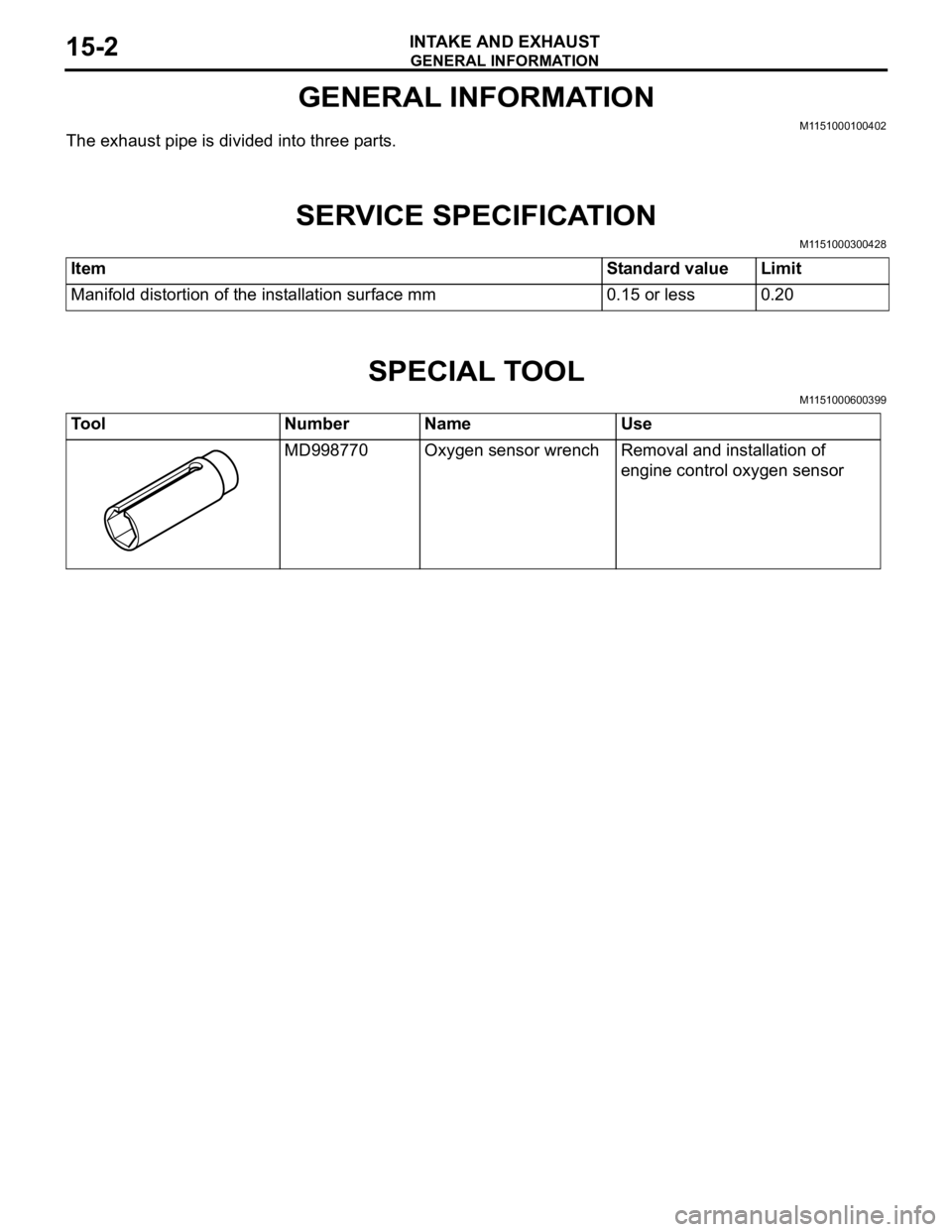
MD998770Oxygen sensor wrenchRemoval and installation of
engine control oxygen sensor
Page 63 of 800
16-1
GROUP 16
ENGINE
ELECTRICAL
CONTENTS
CHARGING SYSTEM . . . . . . . .16-2
GENERAL INFORMATION . . . . . .16-2
SERVICE SPECIFICATIONS. . . . .16-3
SPECIAL TOOL . . . . . . . . . . . . . . .16-3
ON-VEHICLE SERVICE. . . . . . . . .16-3
ALTERNATOR OUTPUT LINE VOLTAGE
DROP TEST . . . . . . . . . . . . . . . . . . . . . 16-3
OUTPUT CURRENT TEST . . . . . . . . . . 16-5
REGULATED VOLTAGE TEST . . . . . . . 16-7
WAVEFORM CHECK USING AN
OSCILLOSCOPE . . . . . . . . . . . . . . . . . . 16-9
ALTERNATOR ASSEMB LY . . . . .16-12
REMOVAL AND INSTALLATION
<4G1> . . . . . . . . . . . . . . . . . . . . . . . . . . 16-12
REMOVAL AND INSTALLATION
<4G6> . . . . . . . . . . . . . . . . . . . . . . . . . . 16-13
DISASSEMBLY AND REASSEMBLY . . 16-15
INSPECTION . . . . . . . . . . . . . . . . . . . . . 16-17
STARTING SYSTEM . . . . . . . . .16-19
GENERAL INFORMATION . . . . . .16-19
SERVICE SPECIFICATIONS. . . . .16-20
STARTER MOTOR ASSEMBLY . .16-21
REMOVAL AND INSTALLATION
<4G1> . . . . . . . . . . . . . . . . . . . . . . . . . . 16-21
REMOVAL AND INSTALLATION
<4G6> . . . . . . . . . . . . . . . . . . . . . . . . . . 16-22
STARTER MOTOR ASSEMBLY
INSPECTION . . . . . . . . . . . . . . . . . . . . . 16-23
DISASSEMBLY AND REASSEMBLY . . 16-26
INSPECTION . . . . . . . . . . . . . . . . . . . . . 16-27
IGNITION SYSTEM . . . . . . . . . 16-30
GENERAL INFORMATION . . . . . .16-30
SERVICE SPECIFICATIONS . . . . .16-31
SPECIAL TOOL . . . . . . . . . . . . . . .16-31
ON-VEHICLE SERVICE . . . . . . . . .16-32
IGNITION COIL (WITH BUILT-IN
POWER TRANSISTOR) CHECK . . . . . . 16-32
RESISTIVE CORD CHECK . . . . . . . . . . 16-32
SPARK PLUG CHECK AND CLEANING
<4G1>. . . . . . . . . . . . . . . . . . . . . . . . . . . 16-32
SPARK PLUG CHECK AND CLEANING
<4G6>. . . . . . . . . . . . . . . . . . . . . . . . . . . 16-33
CAMSHAFT POSITION SENSOR
CHECK . . . . . . . . . . . . . . . . . . . . . . . . . . 16-33
CRANK ANGLE SENSOR CHECK . . . . 16-33
DETONATION SENSOR CHECK . . . . . 16-33
IGNITION SECONDARY VOLTAGE
WAVEFORM CHECK USING AN
OSCILLOSCOPE . . . . . . . . . . . . . . . . . . 16-33
IGNITION COIL RELAY CHECK . . . . . . 16-37
IGNITION COIL . . . . . . . . . . . . . . . .16-38
REMOVAL AND INSTALLATION
<4G1>. . . . . . . . . . . . . . . . . . . . . . . . . . . 16-38
REMOVAL AND INSTALLATION
<4G6>. . . . . . . . . . . . . . . . . . . . . . . . . . . 16-39
CAMSHAFT POSITION SENSOR .16-40
REMOVAL AND INSTALLATION . . . . . . 16-40
CRANKSHAFT POSITION SENSOR16-41
REMOVAL AND INSTALLATION
<4G1>. . . . . . . . . . . . . . . . . . . . . . . . . . . 16-41
REMOVAL AND INSTALLATION
<4G6>. . . . . . . . . . . . . . . . . . . . . . . . . . . 16-42
DETONATION SENSOR . . . . . . . .16-43
REMOVAL AND INSTALLATION . . . . . . 16-43