Special tool MITSUBISHI LANCER 2006 User Guide
[x] Cancel search | Manufacturer: MITSUBISHI, Model Year: 2006, Model line: LANCER, Model: MITSUBISHI LANCER 2006Pages: 800, PDF Size: 45.03 MB
Page 65 of 800
CHARGING SYSTEM
ENGINE ELECTRICAL16-3
SERVICE SPECIFICATIONS
M1161000300258
ItemStandard valueLimit
Alternator output line voltage drop (at 30 A) V−maximum 0.3
Regulated voltage ambient
temperature at voltage regulator V−20°C14.2 − 15.4−
20°C13.9 − 14.9−
60°C13.4 − 14.6−
80°C13.1 − 14.5−
Output current−70 % of normal output current
SPECIAL TOOLM1161000600163
ToolNumberNameUse
MB991519Alterna t or test harn e ssChec king th e alt e rnator
("S" te rminal volt age )
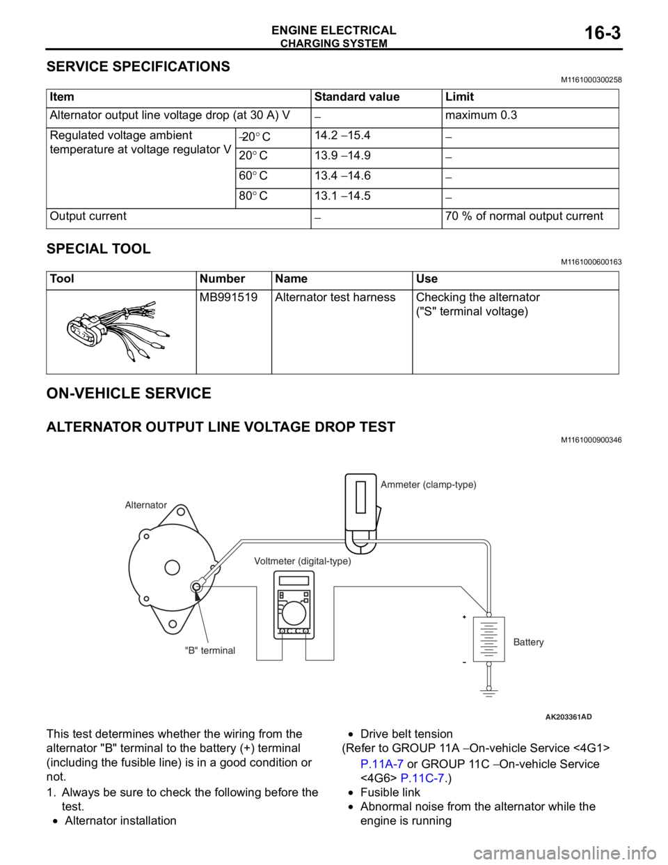
ON-VEHICLE SERV ICE
ALTERNA T O R OUTPUT LINE VOL T AGE DROP TEST
M1161 0009 0034 6
AK203361AD
Alternator Ammeter (clamp-type)
Voltmeter (digital-type)
"B" terminal Battery
This test
determine s whethe r the wiring fro m th e
altern
ator "B" termina l to t he batt e ry (+) terminal
(including the
fusible line ) is in a good condition or
not.
1.Always b e su re to check the following b e fore th e
te st.
•Alternator inst allatio n
•Drive belt tension
(Ref er to GROUP 1 1 A − On-veh icle Service <4G1>
P.11A-7 or GROUP 1 1 C − On-vehicle Service
<4G6> P.11C-7.)
•Fusible link
•Abnormal noise from the altern ator while the
eng
ine is ru nning
Page 69 of 800
Page 70 of 800

CHARGING SYSTEM
ENGINE ELECTRICAL16-8
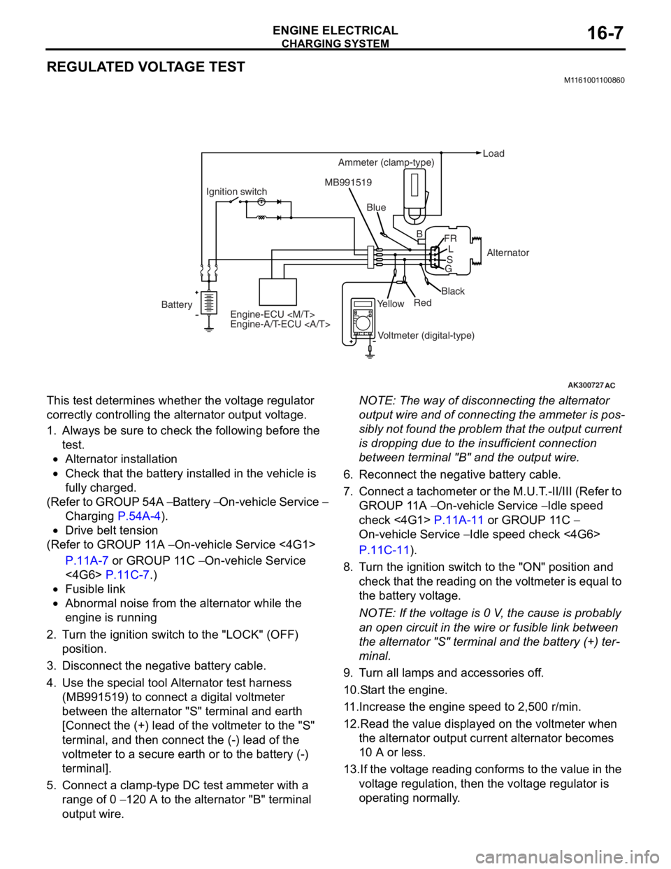
If the voltage is not within the standard value,
there is a malfunction of the voltage regulator or of
the alternator.
14.After the test, lower the engine speed to the idle speed.
15.Turn the ignition switch to the "LOCK" (OFF) position.
16.Remove the tachometer or the M.U.T.-II/III.
17.Disconnect the negative battery cable.
18.Disconnect the ammeter and voltmeter.
19.Connect the alternator output wire to the alternator "B" terminal.
20.Remove the special tool, and return the connector
to the original condition.
21.Connect the negative battery cable.
Voltage Regulation Table
Standard value:
Inspection terminalVoltage regulator ambient
temperature
°C
Voltage V
Terminal "S"−2014.2 − 15.4
2013.9 − 14.9
6013.4 − 14.6
8013.1 − 14.5
Page 93 of 800
IGNITION SYSTEM
ENGINE ELECTRICAL16-31
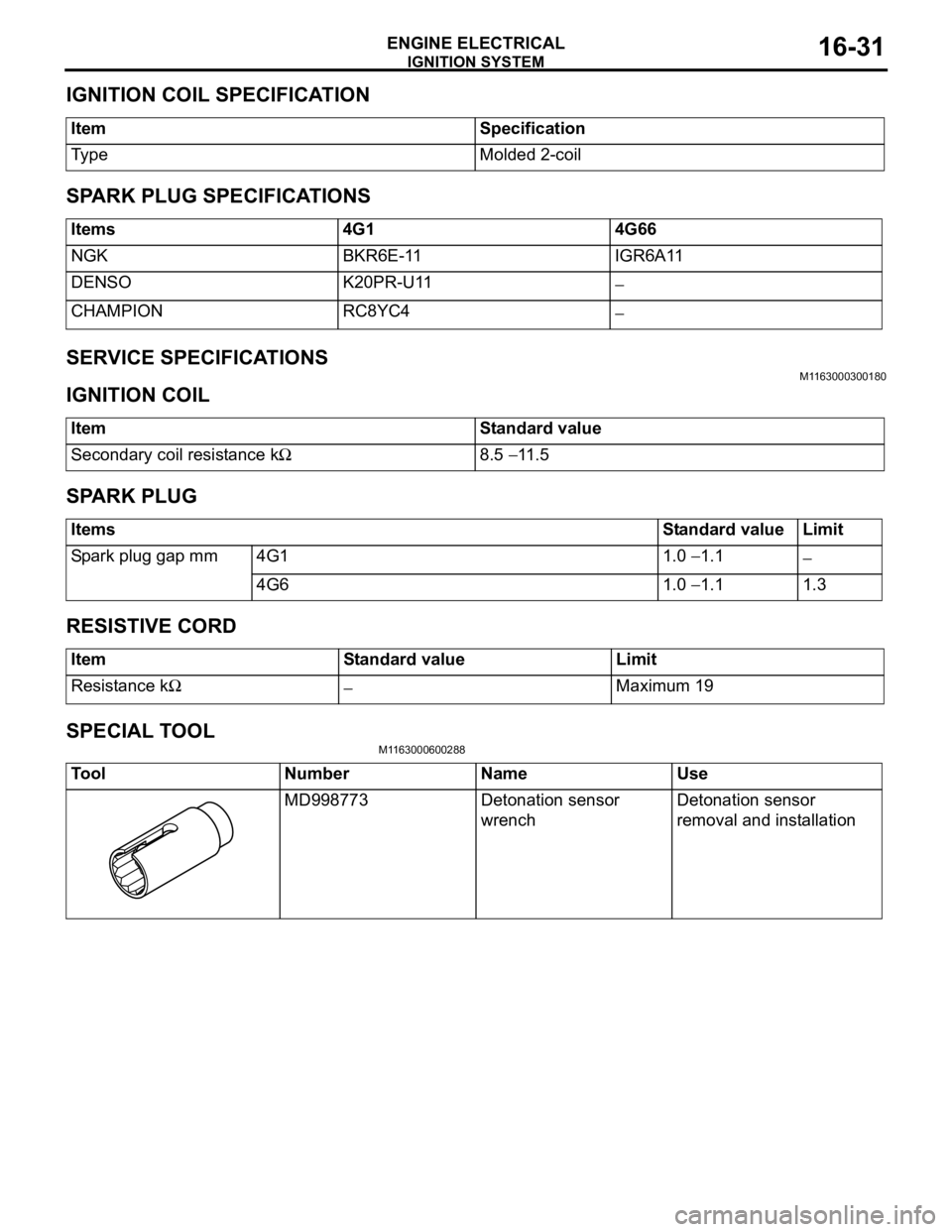
IGNITION COIL SPECIFICATION
ItemSpecification
Ty p eMolded 2-coil
SPARK PLUG SPECIFICATIONS
Items4G14G66
NGKBKR6E-11IGR6A11
DENSOK20PR-U11−
CHAMPIONRC8YC4−
SERVICE SPECIFICATIONSM1163000300180
IGNITION COIL
ItemStandard value
Secondary coil resistance kΩ8.5 − 11.5
SPARK PLUG
ItemsStandard valueLimit
Spark plug gap mm4G11.0 − 1.1−
4G61.0 − 1.11.3
RESISTIVE CORD
ItemStandard valueLimit
Resistance kΩ−Maximum 19
SPECIAL TOOL
M1163000600288
ToolNumberNameUse
MD998773Detonation sensor
wrenchDetonation sensor
removal and installation
Page 133 of 800
26-1
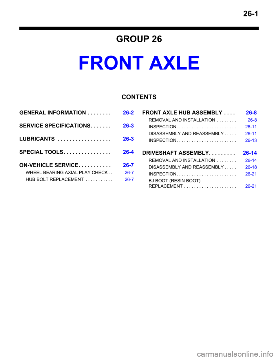
GROUP 26
FRONT AXLE
CONTENTS
GENERAL INFORMATION . . . . . . . .26-2
SERVICE SPECIFICATIONS . . . . . . .26-3
LUBRICANTS . . . . . . . . . . . . . . . . . .26-3
SPECIAL TOOLS . . . . . . . . . . . . . . . .26-4
ON-VEHICLE SERVICE . . . . . . . . . . .26-7
WHEEL BEARING AXIAL PLAY CHECK . . 26-7
HUB BOLT REPLACEMENT . . . . . . . . . . . 26-7
FRONT AXLE HUB ASSEMBLY . . . .26-8
REMOVAL AND INSTALLATION . . . . . . . . 26-8
INSPECTION. . . . . . . . . . . . . . . . . . . . . . . . 26-11
DISASSEMBLY AND REASSEMBLY . . . . . 26-11
INSPECTION. . . . . . . . . . . . . . . . . . . . . . . . 26-13
DRIVESHAFT ASSEMBLY. . . . . . . . .26-14
REMOVAL AND INSTALLATION . . . . . . . . 26-14
DISASSEMBLY AND REASSEMBLY . . . . . 26-18
INSPECTION. . . . . . . . . . . . . . . . . . . . . . . . 26-21
BJ BOOT (RESIN BOOT)
REPLACEMENT . . . . . . . . . . . . . . . . . . . . . 26-21
Page 135 of 800
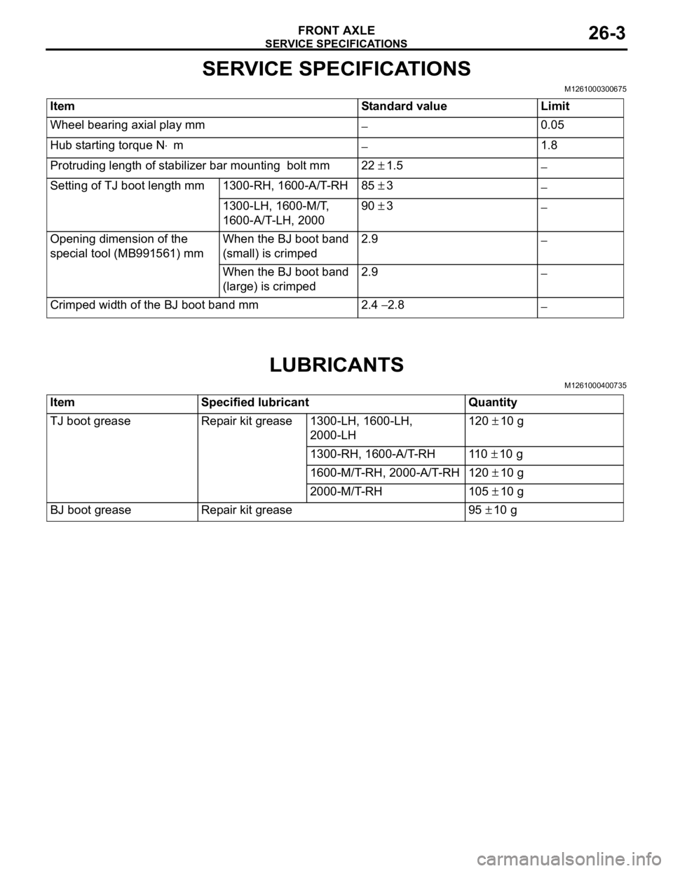
SERVICE SPECIFICATIONS
FRONT AXLE26-3
SERVICE SPECIFICATIONS
M1261000300675
ItemStandard valueLimit
Wheel bearing axial play mm−0.05
Hub starting torque N⋅m−1.8
Protruding length of stabilizer bar mounting bolt mm22 ± 1.5−
Setting of TJ boot length mm1300-RH, 1600-A/T-RH85 ± 3−
1300-LH, 1600-M/T,
1600-A/T-LH, 200090 ± 3−
Opening dimension of the
special tool (MB991561) mmWhen the BJ boot band
(small) is crimped2.9−
When the BJ boot band
(large) is crimped2.9 −
Crimped width of the BJ boot band mm2.4 − 2.8−
LUBRICANTS
M1261000400735
ItemSpecified lubricantQuantity
TJ boot greaseRepair kit grease1300-LH, 1600-LH,
2000-LH120 ± 10 g
1300-RH, 1600-A/T-RH11 0 ± 10 g
1600-M/T-RH, 2000-A/T-RH120 ± 10 g
2000-M/T-RH105 ± 10 g
BJ boot greaseRepair kit grease95 ± 10 g
Page 136 of 800
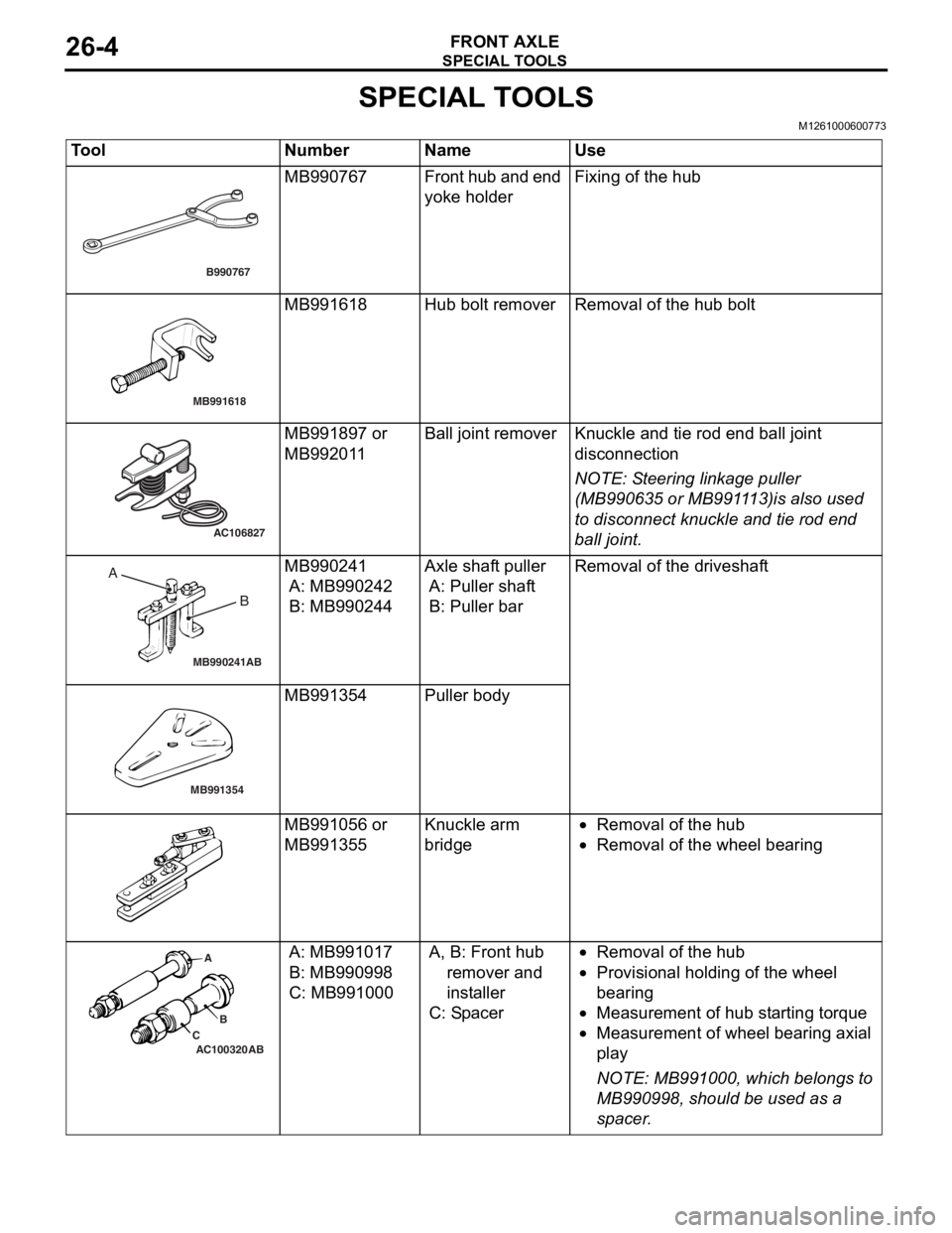
SPECIAL TOOLS
FRONT AXLE26-4
SPECIAL TOOLS
M1261000600773
ToolNumberNameUse
B990767
MB990767Fr o n t hu b a n d en d
yoke holderFixing of the h u b
MB991618
MB991618Hub bolt remo verRemoval of the h ub bolt
AC106827
MB991897 or
MB992
01 1Ball j o int remo verKnuckle and tie rod e nd ball joint
discon
nection
NOTE: St eering linkage pu lle r
(MB990 635 or MB991 1 13)is also u s ed
to disconnect kn uckle an d tie rod en d
bal
l j
o
int.
MB990241AB
A BMB990241
A: MB9902 42
B: MB990244
Axle shaft pu ller
A: Puller shaf t
B: Puller bar
Rem o va l of t h e dri v es h a f t
MB991354
MB991354Pulle r body
MB991 056 or
MB991
355Knuckle a r m
bridg
e•Removal of the hu b
•Removal of the whee l bea ring
AC100320 ABA
B
C
A: MB9910 17
B: MB990998
C: MB99100 0
A, B: Fr ont hu b
remover and
ins t all e r
C: Sp acer
•Removal of the hu b
•Prov ision a l ho ldin g of th e wheel
b
earin g
•Measurement of hub st a r ting t o rque
•Measurement of wh eel b earin g axial
pl
a y
NOTE: MB9 91000, which b e lon g s to
MB9909 98, should be used a s a
sp
acer
.
Page 141 of 800
Page 142 of 800
FRONT AXLE HUB ASSEMBLY
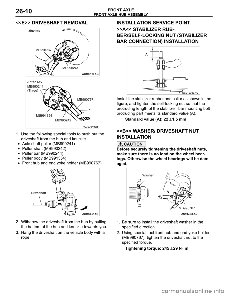
FRONT AXLE26-10
<
AC100128
MB990241
MB990767
AG
AC303949
MB990244
(Three)
MB990767
MB990242
MB991354
AF
1.
Use the fo llo wing special to ols to pu sh ou t the
driveshaf t from the hub an d kn uckle.
•Axle shaf t puller (MB9 90241 )
•Puller shaft (MB990 242)
•Puller bar (MB990 244)
•Puller body (MB99135 4)
•
AC102551
AC
Driveshaft
Front hub a nd end yoke holder (MB99076 7)
2.Withdraw th e driveshaf t from the hu b by pulling
th e botto m of the hub and knuckle towards you .
3.Hang the dr ive s haf t on the vehicle b ody with a
rope.
INST ALLA T ION SER VICE POINT
>>A<< STABILIZER RUB-
BER/SELF-LOCKING NUT (ST A BILIZER
BAR CONNECTION) INST
ALLA TION
AC210393AC
A
I
n st a ll the st a b ili zer rubb er an d coll ar as sho w n in t he
figure
, and t i ghte n the self-locking nut so tha t the
protruding length
of the st abilize r bar mount ing b o lt
protruding p
a rt meet s it s st and ard value (A).
St andard va lue (A): 22 ± 1.5 m m
>>B<< W A SHER/ DRIVESHAFT NUT
INST
ALLA TION
CAUTION
Before securely tightening the driveshaft nuts,
make sure there is no load on the wheel bear
-
ings. Otherwise the wheel bearings will be dam-
aged.
AC102465AD
MB990767
Washer
1. Be sure to install the driveshaft washer in the
specified direction.
2. Using special tool front hub and end yoke holder (MB990767), tighten the driveshaft nut to the
specified torque.
Tightening torque: 245 ± 29 N⋅m
Page 143 of 800
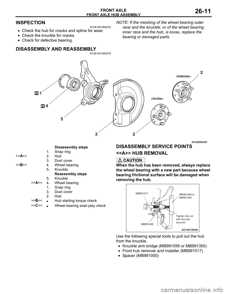
FRONT AXLE HUB ASSEMBLY
FRONT AXLE26-11
INSPECTION
M1261001800242
•Check the hub for cracks and spline for wear.
•Check the knuckle for cracks.
•Check for defective bearing.
NOTE: If the meshing of the wheel bearing outer
race and the knuckle, or of the wheel bearing
inner race and the hub, is loose, replace the
bearing or damaged parts.
DISASSEMBLY AND REASSEMBLY
M1261001900379
AC303659
N
N4
1
5 3 2
AF
2
Disassembly steps
1.Snap ring
<>2.Hub
3.Dust cover
<>4.Wheel bearing
5.Knuckle
Reassembly steps
5.Knuckle
>>A<<4.Wheel bearing
1.Snap ring
3.Dust cover
2.Hub
>>B<<•Hub starting torque check
>>C<<•Wheel bearing axial play check
DISASSEMBL
Y SER V ICE POINTS
< > HUB REMOV A L
CAUTION
When the hub has been removed, always replace
the wheel bearing with a new part because wheel
bearing frictional surface will be damaged when
removing the hub.
AC100130
Tighten the nut
with the bolt
secured MB991056 or
MB991355
MB991017
MB991000 AB
Use the following special tools to pull out the hub
from the knuckle.
•Knuckle arm bridge (MB991056 or MB991355)
•Front hub remover and Installer (MB991017)
•Spacer (MB991000)