cover gasket MITSUBISHI LANCER 2006 Workshop Manual
[x] Cancel search | Manufacturer: MITSUBISHI, Model Year: 2006, Model line: LANCER, Model: MITSUBISHI LANCER 2006Pages: 800, PDF Size: 45.03 MB
Page 10 of 800
ON-VEHICLE SERVICE
ENGINE LUBRICATION12-4
ON-VEHICLE SERVICE
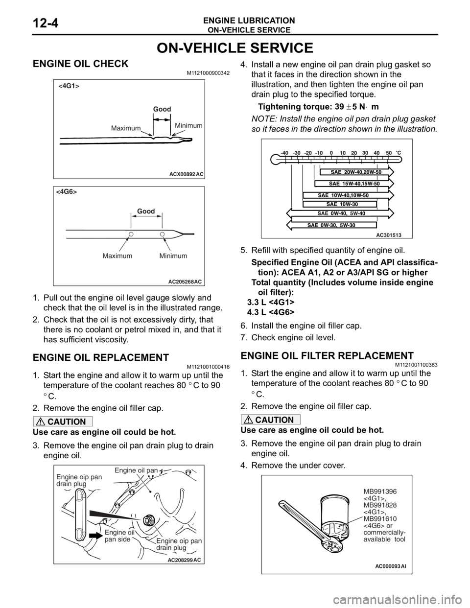
ENGINE OIL CHECKM1121000900342
ACX00892 AC
Good
Maximum Minimum
<4G1>
AC205268
Maximum MinimumGood
AC
<4G6>
1.
Pull ou t the en gine oil level ga uge slowly and
check tha t the o il level is in t he illustrated range.
2.Check t hat the oil is not excessively dirty , that
th ere is no coolant or p e trol mixed in, and that it
ha s s u f f i c ie nt vi sc osi t y .
ENGINE OIL REPLACEMENT
M1121 0010 0041 6
1.S t art the engin e and allow it to war m up until the
te mpera t ure of the coola n t reaches 80
°C to 90
°C.
2.Remove the en gine oil filler ca p.
CAUTION
Use care as engine oil could be hot.
3. Remove the engine oil pan drain plug to drain
engine oil.
AC208299
Engine oil pan
AC
Engine oip pan
drain plug
Engine oip pan
drain plug
Engine oil
pan side
4. Install a new engine oil pan drain plug gasket so
that it faces in the direction shown in the
illustration, and then tighten the engine oil pan
drain plug to the specified torque.
Tightening torque: 39 ± 5 N⋅m
NOTE: Install the engine oil pan drain plug gasket
so it faces in the direction shown in the illustration.
AC301513
5. Refill with specifi ed quantity of engine oil.
Specified Engine Oil (ACEA and API classifica-
tion): ACEA A1, A2 or A3/API SG or higher
Total quantity (Includes volume inside engine
oil filter):
3.3 L <4G1>
4.3 L <4G6>
6. Install the engine oil filler cap.
7. Check engine oil level.
ENGINE OIL FILTER REPLACEMENTM1121001100383
1. Start the engine and allow it to warm up until the temperature of the coolant reaches 80
°C to 90
°C.
2. Remove the engine oil filler cap.
CAUTION
Use care as engine oil could be hot.
3. Remove the engine oil pan drain plug to drain engine oil.
4. Remove the under cover.
AC000093
MB991396
<4G1>,
MB991828
<4G1>,
MB991610
<4G6> or
commercially-
available tool
AI
Page 43 of 800
WATER HOSE AND WATER PIPE
ENGINE COOLING14-29
WATER HOSE AND WATER PIPE
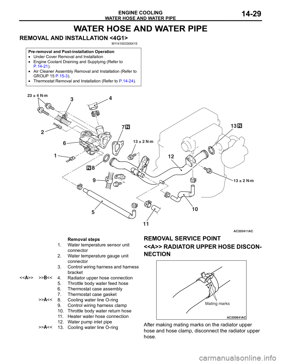
REMOVAL AND INSTALLATION <4G1>M1141003300415
Pre-removal and Post-installation Operation
•Under Cover Removal and Installation
•Engine Coolant Draining and Supplying (Refer to P.14-21).
•Air Cleaner Assembly Removal and Installation (Refer to
GROUP 15 P.15-3).
•Thermostat Removal and Installation (Refer to P.14-24).
AC203411
1
2 3
4
5
6
7
8
10
9
13 ± 2 N·m
23 ± 4 N·m
13 ± 2 N·m
N
N
AC
1112
13
N
Removal steps
1.Water temperature sensor unit
connector
2.Water temperature gauge unit
connector
3.Control wiring harness and harness
bracket
<>>>B<<4.Radiator upper hose connection
5.Throttle body water feed hose
6.Thermostat case assembly
7.Thermostat case gasket
>>A<<8.Cooling water line O-ring
9.Control wiring harness clamp
10.Throttle body water return hose
11 .Heater water hose connection
12.Water pump inlet pipe
>>A<<13.Cooling water line O-ring
REMOV
A L SER VICE POINT
<> RADIAT OR UPPER HOSE DISCON-
NECTION
AC200641AC
Mating marks
After making matin g ma rks on the radia t or upp er
hose
and h o se clamp, disconnect the radia t or upp er
hose
.
Page 54 of 800
AC303619
4.0 ± 1.0 N·m
4.0 ± 1.0 N·m10*
9* 4
1* 5
11
12 ± 1 N·m 9.0 ± 1.0 N·m
9.0 ± 1.0 N·m
AB
12 ± 1 N·m
Clamp
8*
3*
<4G6>
6
7
N
2
8.8 ± 1.0 N·m
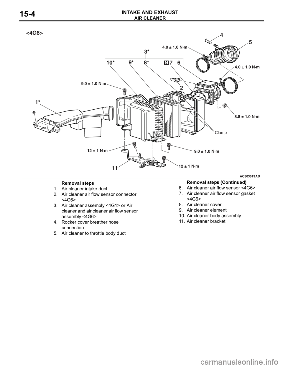
Removal steps
1.Air cleaner intake duct
2.Air cleaner air flow sensor connector
<4G6>
3.Air cleaner assembly <4G1> or Air
cleaner and air cleaner air flow sensor
assembly <4G6>
4.Rocker cover breather hose
connection
5.Air cleaner to throttle body duct
6.Air cleaner air flow sensor <4G6>
7.Air cleaner air flow sensor gasket
<4G6>
8.Air cleaner cover
9.Air cleaner element
10.Air cleaner body assembly
11 .Air cleaner bracket
AIR CLEA NER
INTAKE AN D EXHAU ST15-4
Removal steps (Continued)
Page 55 of 800
INLET MANIFOLD
INTAKE AND EXHAUST15-5
INLET MANIFOLD
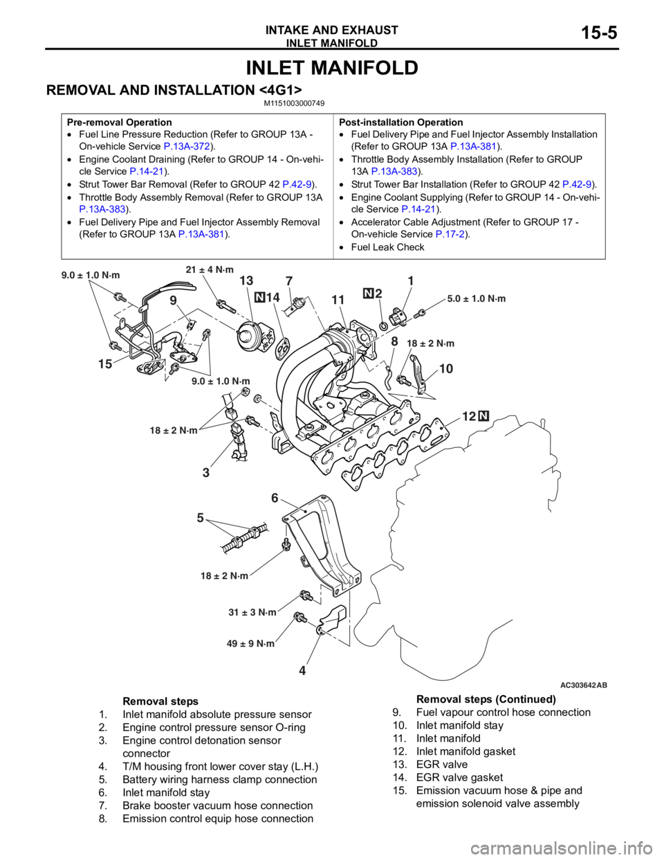
REMOVAL AND INSTALLATION <4G1>M1151003000749
Pre-removal Operation
•Fuel Line Pressure Reduction (Refer to GROUP 13A -
On-vehicle Service
P.13A-372).
•Engine Coolant Draining (Refer to GROUP 14 - On-vehi-
cle Service P.14-21).
•Strut Tower Bar Removal (Refer to GROUP 42 P.42-9).
•Throttle Body Assembly Re moval (Refer to GROUP 13A
P.13A-383).
•Fuel Delivery Pipe and Fuel Injector Assembly Removal
(Refer to GROUP 13A
P.13A-381).
Post-installation Operation
•Fuel Delivery Pipe and Fuel Injector Assembly Installation
(Refer to GROUP 13A
P.13A-381).
•Throttle Body Assembly Inst allation (Refer to GROUP
13A
P.13A-383).
•Strut Tower Bar Installati on (Refer to GROUP 42 P.42-9).
•Engine Coolant Supplying (Refer to GROUP 14 - On-vehi-
cle Service P.14-21).
•Accelerator Cable Adjustment (Refer to GROUP 17 -
On-vehicle Service
P.17-2).
•Fuel Leak Check
AC303642AB
15
36
5
4 12
10
7
1
2
11
9 13
14
21 ± 4 N·m
9.0 ± 1.0 N·m
9.0 ± 1.0 N·m
18 ± 2 N·m
18 ± 2 N·m 18 ± 2 N·m
5.0 ± 1.0 N·m
31 ± 3 N·m
49 ± 9 N·m
N
N
N
8
Removal steps
1.Inlet manifold absolute pressure sensor
2.Engine control pressure sensor O-ring
3.Engine control detonation sensor
connector
4.T/M housing front lower cover stay (L.H.)
5.Battery wiring harness clamp connection
6.Inlet manifold stay
7.Brake booster vacuum hose connection
8.Emission control equip hose connection
9.Fuel vapour control hose connection
10.Inlet manifold stay
11 .Inlet manifold
12.Inlet manifold gasket
13.EGR valve
14.EGR valve gasket
15.Emission vacuum hose & pipe and
emission solenoid valve assembly
Removal steps (Continued)
Page 58 of 800
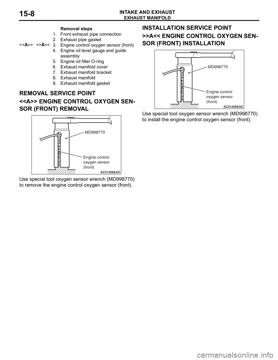
Removal steps
1.Front exhaust pipe connection
2.Exhaust pipe gasket
<>>>A<<3.Engine control oxygen sensor (front)
4.Engine oil level gauge and guide
assembly
5.Engine oil filler O-ring
6.Exhaust manifold cover
7.Exhaust manifold bracket
8.Exhaust manifold
9.Exhaust manifold gasket
EXHAUST MANIFOLD
INTAKE AND EXHAUST15-8
REMOVAL SERVICE POINT
<> ENGINE CONTROL OXYGEN SEN-
SOR (FRONT) REMOVAL
AC212566AC
MD998770
Engine control
oxygen sensor
(front)
Use spe c ia l tool oxyg en sen s or wrench (MD9987 70)
to remove t
he eng ine contro l oxygen sen s or (fro nt).
INSTALLA T ION SER VICE POINT
>>A<< ENGINE CONT ROL OXYGEN SEN-
SOR (FRONT) INSTALLA TION
AC212566AC
MD998770
Engine control
oxygen sensor
(front)
Use spe c ia l tool oxyg en sen s or wrench (MD9987 70)
to inst
all the eng ine contro l oxyge n sen s or (f ront).
Page 59 of 800
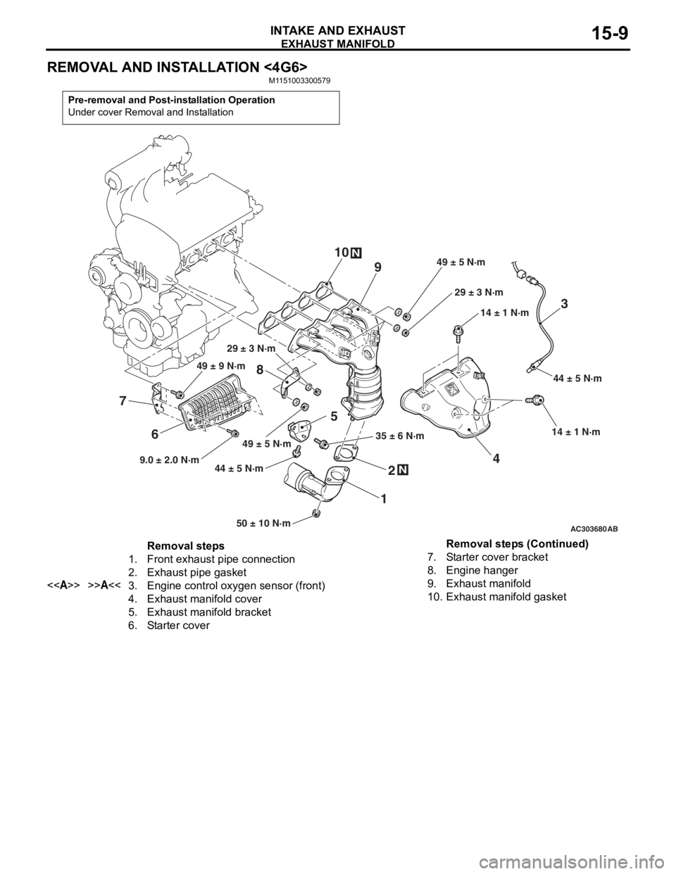
EXHAUST MANIFOLD
INTAKE AND EXHAUST15-9
REMOVAL AND INSTALLATION <4G6>
M1151003300579
Pre-removal and Post-installation Operation
Under cover Removal and Installation
AC30368050 ± 10 N·m
44 ± 5 N·m
35 ± 6 N·m14 ± 1 N·m
14 ± 1 N·m
49 ± 5 N·m 29 ± 3 N·m
29 ± 3 N·m
N
3
4
1 2
5
N
8 944 ± 5 N·m
AB
1049 ± 5 N·m
6
7
9.0 ± 2.0 N·m 49 ± 9 N·m
Removal steps
1.Front exhaust pipe connection
2.Exhaust pipe gasket
<>>>A<<3.Engine control oxygen sensor (front)
4.Exhaust manifold cover
5.Exhaust manifold bracket
6.Starter cover
7.Starter cover bracket
8.Engine hanger
9.Exhaust manifold
10.Exhaust manifold gasket
Removal steps (Continued)
Page 179 of 800
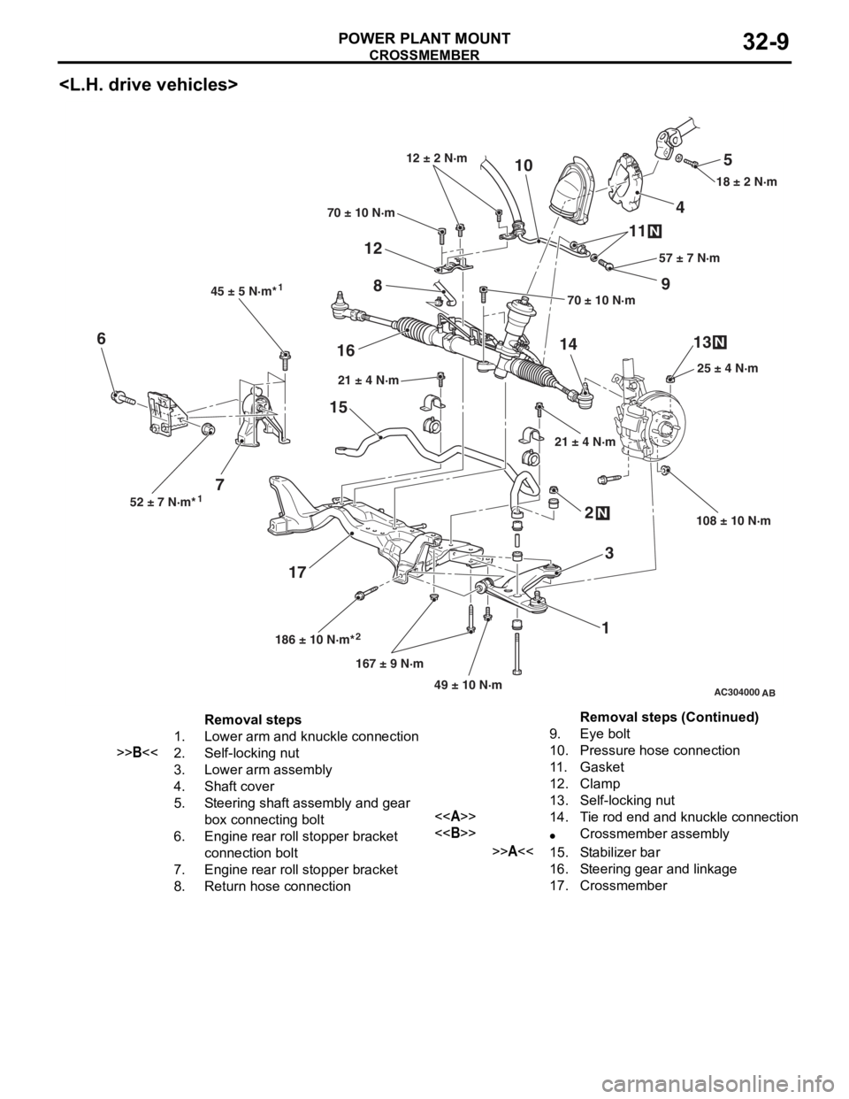
CROSSMEMBER
POWER PLANT MOUNT32-9
AC304000
108 ± 10 N·m25 ± 4 N·m 18 ± 2 N·m
70 ± 10 N·m
21 ± 4 N·m
21 ± 4 N·m
186 ± 10 N·m* 167 ± 9 N·m49 ± 10 N·m
52 ± 7 N·m* 45 ± 5 N·m*
70 ± 10 N·m
57 ± 7 N·m
12 ± 2 N·m
5
4
10
9
11
8
12
1413
6
7 16
15
17 2
3
1
N
N
N
2
1 1
AB
Removal steps
1.Lower arm and knuckle connection
>>B<<2.Self-locking nut
3.Lower arm assembly
4.Shaft cover
5.Steering shaft assembly and gear
box connecting bolt
6.Engine rear roll stopper bracket
connection bolt
7.Engine rear roll stopper bracket
8.Return hose connection
9.Eye bolt
10.Pressure hose connection
11 .Gasket
12.Clamp
13.Self-locking nut
<>14.Tie rod end and knuckle connection
<>•Crossmember assembly
>>A<<15.Stabilizer bar
16.Steering gear and linkage
17.Crossmember
Removal steps (Continued)
Page 180 of 800
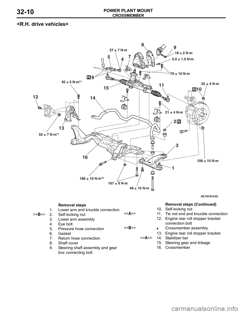
CROSSMEMBER
POWER PLANT MOUNT32-10
AC101614
12
3
4
5
6 7
8
9
10
11
12
13 14
15
16
45 ± 5 N·m*¹
52 ± 7 N·m*¹ 186 ± 10 N·m*²167 ± 9 N·m
49 ± 10 N·m 108 ± 10 N·m25 ± 4 N·m
21 ± 4 N·m 70 ± 10 N·m
5.0 ± 1.0 N·m
18 ± 2 N·m
57 ± 7 N·m
N
N
N
AE
Removal steps
1.Lower arm and knuckle connection
>>B<<2.Self-locking nut
3.Lower arm assembly
4.Eye bolt
5.Pressure hose connection
6.Gasket
7.Return hose connection
8.Shaft cover
9.Steering shaft assembly and gear
box connecting bolt
10.Self-locking nut
<>11 .Tie rod end and knuckle connection
12.Engine rear roll stopper bracket
connection bolt
<>•Crossmember assembly
13.Engine rear roll stopper bracket
>>A<<14.Stabilizer bar
15.Steering gear and linkage
16.Crossmember
Removal steps (Continued)
Page 272 of 800
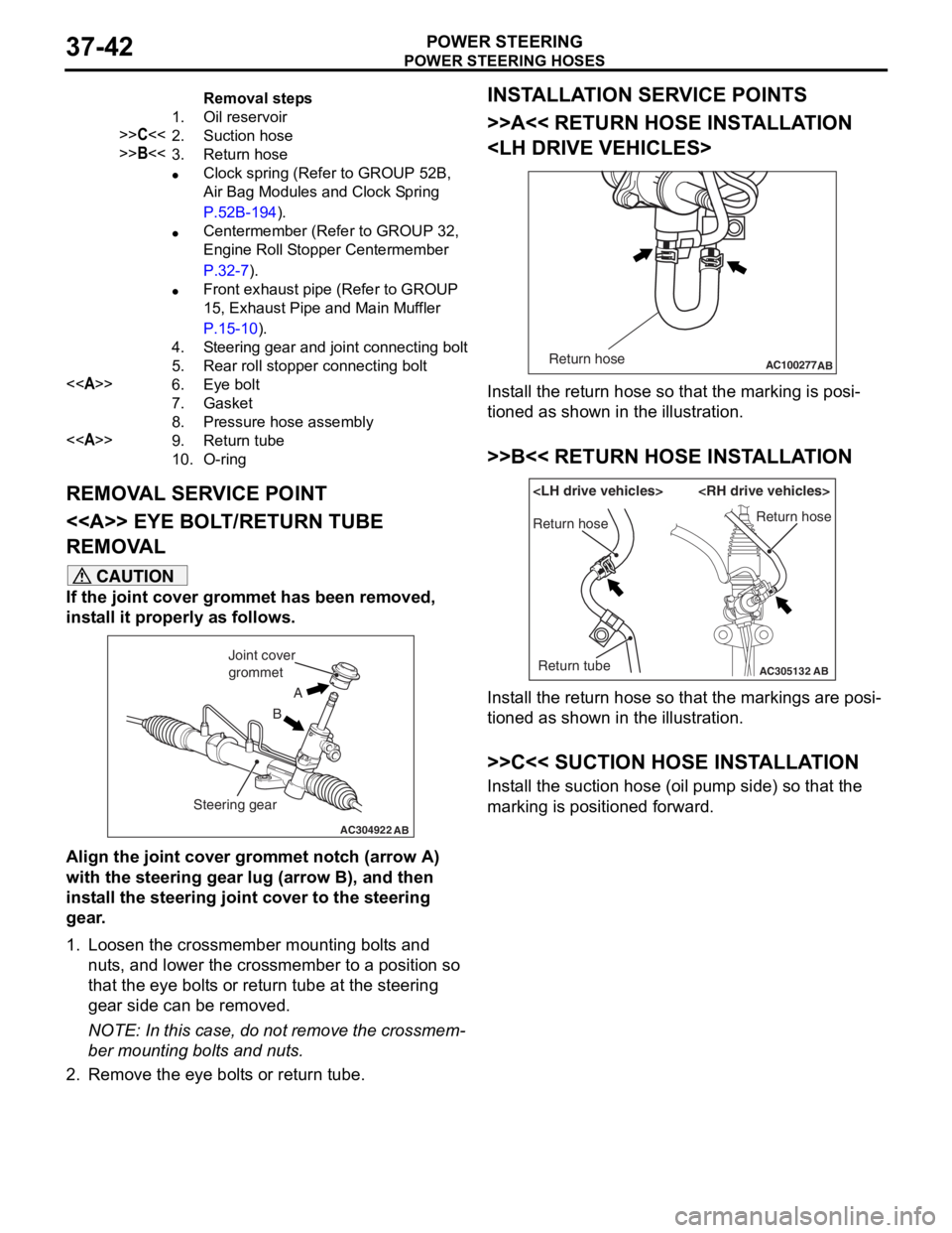
Removal steps
1.Oil reservoir
>>C<<2.Suction hose
>>B<<3.Return hose
•Clock spring (Refer to GROUP 52B,
Air Bag Modules and Clock Spring
P.52B-194).
•Centermember (Refer to GROUP 32,
Engine Roll Stopper Centermember
P.32-7).
•Front exhaust pipe (Refer to GROUP
15, Exhaust Pipe and Main Muffler
P.15-10).
4.Steering gear and joint connecting bolt
5.Rear roll stopper connecting bolt
<>6.Eye bolt
7.Gasket
8.Pressure hose assembly
<>9.Return tube
10.O-ring
POWE R STEERING HOSES
POWER S T E E RING37-42
REMOVA L SER V ICE POINT
<> EYE BOLT /RETURN TUBE
REMOV
A L
CAUTION
If the joint cover grommet has been removed,
install it properly as follows.
AC304922AB
A
B
Joint cover
grommet
Steering gear
Align the joint cover grommet notch (arrow A)
with the steering gear lug (arrow B), and then
install the steering joint cover to the steering
gear.
1. Loosen the crossmember mounting bolts and nuts, and lower the crossmember to a position so
that the eye bolts or return tube at the steering
gear side can be removed.
NOTE: In this case, do not remove the crossmem-
ber mounting bolts and nuts.
2. Remove the eye bolts or return tube.
INSTALLATION SERVICE POINTS
>>A<< RETURN HOSE INSTALLATION
AC100277 ABReturn hose
Install the return hose so that the marking is posi-
tioned as shown in the illustration.
>>B<< RETURN HOSE INSTALLATION
AC305132AB
Return hose
Return tubeReturn hose
Install the return hose so that the markings are posi-
tioned as shown in the illustration.
>>C<< SUCTION HOSE INSTALLATION
Install the suction hose (oil pump side) so that the
marking is positioned forward.